tradespace for on-orbit assemblers and servicers
The MIT Faculty has made this article openly available.
Please share
how this access benefits you. Your story matters.
Citation
Jewison, Christopher et al. "Definition and testing of an
architectural tradespace for on-orbit assemblers and servicers"
65th International Astronautical Congress, September 29-October 3,
2014.
As Published
http://www.iafastro.org/events/iac/iac-2014/
Publisher
International Astronautical Federation
Version
Author's final manuscript
Citable link
http://hdl.handle.net/1721.1/105518
Terms of Use
Article is made available in accordance with the publisher's
policy and may be subject to US copyright law. Please refer to the
publisher's site for terms of use.
IAC-14-D1-4.1x23285
DEFINITION AND TESTING OF AN ARCHITECTURAL TRADESPACE FOR ON-ORBIT ASSEMBLERS AND SERVICERS
Christopher Jewison
Massachusetts Institute of Technology, United States, [email protected]
David Sternberg, Bryan McCarthy, David W. Miller, Alvar Saenz-Otero
Massachusetts Institute of Technology, United States, {davister, bpm, millerd, alvarso}@mit.edu
This paper proposes a set of eight architectures that fully span the design tradespace of on-orbit assembler and servicer satellites. A framework is presented that defines the tradespace for servicing and assembly architectures across the three axes of distributed vs. centralized functionality, proximity operation vs. fully captured operations, and integrated vs. external servicing/assembly satellites. A qualitative analysis of the architectural tradespace details the advantages and disadvantages of each of the core architectures. In addition, the paper discusses current and future hardware-in-the-loop testing of various architectures in a sequence of iterative and incremental tests in ground and microgravity environments as part of the Synchronized Position Hold Engage and Reorient Experimental Satellites (SPHERES) facility. New hardware is being sent to the International Space Station to provide quantitative validation of the previously qualitative trades within this space. The paper describes how the results from this testing and the planned test sequences for the remaining architectures will reduce risk for on-orbit assembly and servicing missions.
I. MOTIVATION
Given limited launch vehicle lifting capabilities and fairing size constraints, the concept of staged deployment of space systems through multiple launches enables the construction of large space structures once on orbit. This staged assembly is well illustrated by the decade-spanning construction of the International Space
Station (ISS)1. However, on-orbit assembly is not only
of interest to those missions with launch-vehicle-constrained maximum size and mass, but also to those that require substantial reconfiguration after orbit
insertion such as large space telescopes2,3, exploration
systems4, or communication satellites5.
On-orbit servicing of space systems can be used to extend satellite lifetimes or upgrade the performance of a subsystem. For high value space assets, services include, amongst others, repairing or replacing failed or outdated components and refueling depleted propellant tanks. The benefits of on-orbit servicing can clearly be seen through the Hubble Space Telescope servicing
missions6. Other servicing demonstrations and missions
include Orbital Express7, Phoenix8, and DEOS9.
Although the goals of assembly and servicing are somewhat different, similar system architectures can be developed that are able to perform both functions. Of course, a specific architecture may be better at servicing than assembling, but a systems engineer for either mission type should be able to draw from the same tradespace of designs.
The topic of on-orbit servicing and assembly has
been popular in literature10,11,12,13,14,15, but as far as the
authors are aware, there has been no comprehensive study of the full tradespace of on-orbit assemblers and servicers. This study needs to be performed to ensure
future systems are selected from only the most efficient and lowest risk architectures in the space. Choosing the correct architecture could mean the difference between a profitable, long-term, multi-mission service and a cost overrun, single-mission demonstration. For assembler and servicer spacecraft to successfully provide a valued service on orbit, the full tradespace of possible design options needs to be examined in detail.
Designs throughout the full tradespace should be evaluated against a set of metrics to provide quantitative comparison. Metrics should capture costs and benefits of architectures in terms of complexity, risk, resource allocation and time. In this paper, the evaluations of these metrics are first completed qualitatively, and then a plan is discussed to perform a quantitative evaluation of the metrics and validation of the initial analysis. The end goal is to perform a multidisciplinary system design optimization over the full tradespace with experimental validation of the metric scores.
However, before these steps can be performed, there must exist a well-defined set of architectures to test that fully spans the tradespace. This paper proposes the definition, presents a qualitative analysis of chosen architectures, and discusses current and future experiments in support of quantifying the analysis.
II. ON-ORBIT ASSEMBLY AND SERVICING TRADESPACE
II.I Defining the Tradespace
When performing a system analysis, particularly when attempting to optimize system architecture, it is important that a full range of system designs be evaluated and compared. A complete characterization of the tradespace of possible system architectures is thus
required before performing the analysis. The discussion then becomes similar to several linear algebra concepts. In linear algebra, a set of linearly independent vectors is known as a basis and is said to span a vector space defined by all possible linear combinations of the vectors. To define a system architecture tradespace, one therefore needs to find appropriate basis vectors that span the desired tradespace. This selection of a basis can be difficult however. A basis that is composed of orthogonal vectors (e.g., the Cartesian coordinate frame) can be thought of as a better basis for that space than one consisting of vectors with high dot products. Thus, one would like to find an orthogonal basis, or a basis that is close to orthogonal, to define an architectural tradespace. If the chosen basis is not orthogonal, there could be clustering of important designs or large gaps in the feasible space.
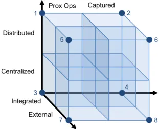
In the case of on-orbit servicers and assemblers, the tradespace can be defined by a set of three basis vectors. These basis vectors make up the axes of a three-dimensional space of possible system architectures. The first axis ranges from a centralized servicing/assembly function to one distributed amongst multiple entities. The second axis ranges from solely using propulsive proximity operations to maneuvering in a fully captured manner with robotic arms or a similar berthing method. The third ranges from a servicing/assembly function integrated directly into the spacecraft to an external craft performing the servicing or assembling. The axes are not binary decisions, but include discrete subdivisions to represent various levels that fall between two extremes on each axis. Thus, the space is divided into octants, where design subspaces are classified according to Fig. 1. For the purposes of illustration, the extreme designs are chosen as architectures one through eight, as shown by the labeled corner points in Fig. 1.
Prox Ops Captured
Integrated External Centralized Distributed 1 2 3 4 5 6 7 8
Fig. 1: Tradespace visualization on three axes The chosen basis for this tradespace seems to represent the desired space and important trades well.
All eight subspaces contain a variety of feasible architectures, and at first analysis there does not seem to be any design clusters or gaps in the defined space. Fig. 2 illustrates these eight extreme architectures in a sample concept of operations (CONOPS), in which the goal is for the assembler/servicer spacecraft to reconfigure an on-orbit spacecraft into its functional geometry. The CONOPS shown in Fig. 2 is meant to be fairly generic, such that it can apply to a servicing mission where modules are being swapped, repaired or refueled, but also can apply to an assembly mission where modules are being reconfigured or added.
Shown in Fig. 2, Architecture 1 is an integrated,
distributed, and proximity operations focused
architecture that has several active spacecraft modules built into the main spacecraft for launch. These modules separate and perform reconfiguration of the spacecraft using propulsive maneuvers and docking ports. In contrast, Architecture 3, the centralized version, only has one active module that maneuvers to reposition the passive modules. And, to finish off the integrated architectures, Architecture 2 and 4 are simply the fully captured versions of Architecture 1 and 3 respectively. In Architecture 2 and 4, the active modules are equipped with robotic arms to facilitate continuous berthing. Finally, Architectures 5 through 8 are the externalized versions of Architectures 1 through 4 respectively. Having an external architecture means that the active modules are launched separately, potentially bring additional passive modules (green) with them, and depart after the service or assembly is completed.
Included in Fig. 2 are some suggested nicknames for the different architectures, that hopefully help one identify an architecture without referencing the illustrations. “Crew” are intended to resemble a group of construction crewmembers working on a building at the same time. A “Spider” is a lone worker, crawling around to complete tasks on its web, and the “Carrier” resembles an aircraft carrier, while the remaining nicknames are deemed sufficiently self-explanatory.
Several existing and proposed missions fall nicely into the framework described in this section. A sampling from available literature on assembly and servicing missions yields several sources for subspaces
defined by Architecture 110,16,17; Architecture 218;
Architecture 319; Architecture 42; Architecture 510,17,20;
Architecture 710,21,22,23,24,25,26; and Architecture
82,26,27,28,29. The amount of literature on a specific
architecture tells a story about how much that type of system has been researched or imagined in the past. A low amount of literature either means that the design is a new concept, yet to be explored, or means that the design is infeasible and should not be explored. Those designs with substantial literature are well known and should provide a good basis for verification and validation of metric evaluations.
1 4 3 2 5 6 5 7 4 3 2 1 6 5 7 4 3 2 1 6 5 7 4 3 2 1 6 5 7 4 3 2 1 6 5 7 4 3 2 1 6 5 7 4 3 2 1 6 Architecture 1: “Beehive” Integrated, Distributed, Prox Ops
1 4 3 2 5 6 5 7 4" 3 2 1 6 5 7 4" 3 2 1 6 5 7 4" 3 2 1 6 5 7 4" 3 2 1 6 5 7 4" 3 2 1 6 4" 3 2 1 5 7 6
Architecture 2: “Integrated Crew” Integrated, Distributed, Captured
1 4 3 2 5 6 5 4" 3 2 1 4" 3 2 1 5 4" 3 2 1 5 5 4" 3 2 5 4" 3 2 1 4" 3 2 1 5 1
Architecture 3: “Integrated Tug” Integrated, Centralized, Prox Ops
1 4 3 2 5 6 4" 3 2 1 5 5 4" 3 2 1 3 5 5 4" 3 2 1 5 4" 3 2 1 4" 3 2 1 5 4" 2 1 Architecture 4: “Spider” Integrated, Centralized, Captured
1 4 3 2 5 6 5 7 4" 3 2 1 6 4" 3 2 1 5 6 4" 3 2 1 7 5 4" 3 2 1 7 5 6 4" 3 2 1 7 4" 3 2 1 6 5 7 6 5 7 6 9 8 9 8 8 9 9 8 9 8 8 9 1 4 3 2 5 6 5 6 3 1 7 5 6 4" 3 2 1 7 5 6 4" 3 2 1 7 5 7 6 5 7 6 5 7 6 4" 3 2 1 4" 2 4" 3 2 1 4" 3 2 1 9 8 9 8 9 8 8 9 9 8 9 8 1 4 3 2 5 6 5 5 4" 3 2 1 5 4" 3 2 1 5 5 5 3 2 1 4" 3 2 1 4" 3 2 1 4" 4" 3 2 1 9 8 9 8 9 8 9 8 9 8 9 8 1 4 3 2 5 6 4" 2 1 1 2 5 4" 3 2 1 5 4" 3 2 1 5 3 5 3 5 5 4" 3 2 1 4" 4" 3 2 1 9 8 9 8 9 8 8 9 9 8 9 8 Architecture 8: “Shuttle” External, Centralized, Captured Architecture 7: “External Tug”
External, Centralized, Prox Ops
Architecture 6: “External Crew” External, Distributed, Captured Architecture 5: “Carrier”
External, Distributed, Prox Ops
Passive module External module Robotic arm Active module
II.II Assessment of Architecture Merit
As discussed earlier, the final goal is to perform a systems level optimization to select the best architecture for on-orbit servicing or assembling. To accomplish this analysis, a set of metrics is required. Each design will need to be evaluated against these metrics to assess how well it meets the needs of assembly and servicing missions. A simple way to think about metrics is in terms of costs, or negative impacts to mission success. Costs can take the form of financial burden, time spent, difficulty in design, complexity, and risk of operations, among others. For the on-orbit servicing and assembly problem, some specific metrics that fall in these general categories should be considered.
The first costs to consider are those associated with mobility. There are costs related to performing a rendezvous between the assembler/servicer and the target spacecraft, and costs related to the propellant consumption required throughout the mission. Different technology developments, including case-specific sensor and actuator suites, are needed for different architectures depending on whether rendezvous is required. If more propellant-expensive proximity maneuvers are performed, the spacecraft will need large fuel tanks or may require on-orbit refueling.
A second category of costs corresponds to decision making, specifically in the guidance, navigation and control framework. This cost can be that of the complexity of the control algorithm used, the number of entities being controlled at the same time, or inherent physical model of the problem. The cost is correlated to
the difficulty of engineering the control algorithms, the computation time required, and the response time of the system to complete a task. Distributed systems will generally be more complex than centralized systems, but have potential to reduce response time.
The third area of cost to examine is that of the type of actions required for a specific CONOPS. For the robotic assembly or servicing problem, these actions can be grouped into fuel consuming, proximity operations and fully captured, robotic arm manipulations. Depending on the architecture, more of one type of maneuvers may be performed, or more total actions will be required to complete a task.
A final but important cost should be risk. The probability of mission failure increases with more complex maneuvers, with more moving parts, with more aggressive control, and with lower sensing knowledge. In the future, financial cost should also be predicted, and will be an important metric. However accurate estimates cannot be confidently made, because very few of these architectures have been executed successfully, and the benefits of modularity, servicing and assembly involve significant uncertainty.
The proposed eight architectures have been qualitatively analyzed against these metrics as shown in Fig. 3. Each architecture is rated from low to high cost in each category based on the CONOPS depicted in Fig. 2. Looking forward, a more detailed, quantitative evaluation of the architectures against these metrics is required to complete the system architecture optimization analysis described earlier.
Cost Architecture 1 Integrated Distributed Prox Ops Beehive 2 Integrated Distributed Captured Integrated Crew 3 Integrated Centralized Prox Ops Integrated Tug 4 Integrated Centralized Captured Spider 5 External Distributed Prox Ops Carrier 6 External Distributed Captured External Crew 7 External Centralized Prox Ops External Tug 8 External Centralized Captured Shuttle Mobility Rendezvous Propellant Decisions Complexity of Control Time Efficiency Actions Proximity Operations Robotic Arm Manipulation Risk
Low Cost Medium Cost High Cost
III. INCREMENTAL AND ITERATIVE TESTING III.I. Testing Process
All testbeds must be able to test a hypothesis conclusively through incremental and iterative testing in repeatable test conditions. The testing increments must build upon one another to reduce risks pertaining to the final flight missions, such as those associated with technologies still in their formative development stages or those associated with unknowns in the flight system. Each iteration represents a complete testing sequence, thereby allowing the data from multiple iterations to be carefully combined and analyzed to determine the overall success of the testing. The data from each increment, however, is derived from the collection of data from multiple iterations.
Each testing iteration of a given increment must be performed in identical operating conditions as the other iterations of that increment in order to compare results across tests. For the tests described in this paper, these conditions center on the ability to maneuver with the same degrees of freedom (DOF) as the final flight hardware in the space environment. Unfortunately, the space environment cannot be fully replicated on the ground. While vacuum, thermal, and radiation compliance of space hardware can be tested terrestrially, and complicated testbeds can be developed to simulate orbital dynamics and field of regard, extended microgravity cannot be replicated. Only spaceflight can
provide long duration microgravity testing
opportunities.
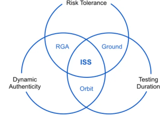
The International Space Station provides the most accessible long duration microgravity environment for conducting extensive testing. Fig. 4 shows how the ISS provides a unique combination of long duration testing opportunities in a risk tolerant environment with the dynamic authenticity of microgravity. As a result, the ISS is an ideal platform with which to conduct developmental testing for on-orbit servicing and assembly architectures. Risk Tolerance Dynamic Authenticity Testing Duration ISS Orbit RGA Ground
Fig. 4: ISS testing environmental conditions30
It is crucial to methodically plan the sequence of testing iterations prior to beginning the testing phase of a flight project. Though a lesser number of testing
increments generally corresponds to a less expensive test campaign, each increment correspondingly bears higher risks and becomes less fault-tolerant. Likewise, a larger number of testing increments yields a more expensive testing campaign, but one that is capable of providing additional fault-tolerance at each stage. A proper balance must be found.
Once the testing sequence is defined, the required testbeds can be created and tests can be run. The testbeds, however, will likely be at a different scale than the final flight hardware. For example, instead of testing the dynamics of a fully assembled spacecraft, a small scale version may be created for detailed study. Results from these tests must therefore be scaled appropriately to reduce full scale risks. For each iteration, the role of scaling is to determine the full scale behavior from small scale testbeds.
Full scale effects can be scaled using a variety of scale modeling techniques, including those developed
by Crawley31 and Gronet32. Their research provides a
means to scale a system based on geometric bases. The scaling laws that they derived allow traceability to be maintained to the final flight system, thereby enabling testing with several testbeds at multiple scales over several testing iterations. Maintaining traceability from one testbed to another and to the final flight system is paramount. The applicable software and hardware must be tested in concert and in authentic operational conditions over the entire process. Scaling laws therefore enable full scale, on-orbit risks to be reduced based on research performed on small scale testbeds with various experimental setups and operation in
different space conditions.30
III.II. SPHERES FACILITY
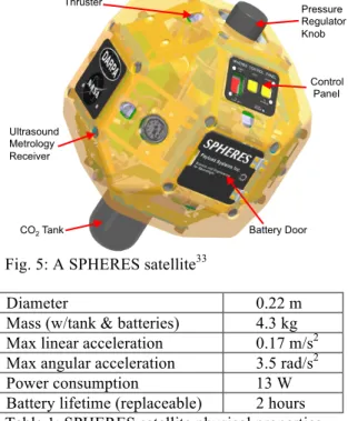
In order to develop a new testbed devoted to on-orbit assembler and servicer testing, a directly traceable and scalable system is required. The Synchronized Position Hold Engage and Reorient Experimental Satellites (SPHERES) facility is currently the only testbed that can operate both in the ground and ISS environments, since three satellites are located in ground laboratories and three satellites are located aboard the ISS as part of the US National Laboratory. The SPHERES satellites themselves were designed started in 1999 as a formation flight testbed, but with extensible capabilities to new areas that directly enable assembly and servicing testing, including docking and undocking, vision based navigation, and satellite reconfiguration.
Each satellite has its own attitude determination and control, guidance and navigation, communication, propulsion, power, structures, avionics, and payload subsystems. As the satellites are not designed to operate outside the confines of the ISS or standard laboratory environments, the satellites do not have a dedicated thermal system, nor are the components radiation
hardened. Two sets of 12V battery packs supply power and 12 cold gas thrusters provide propulsive force. The
batteries and CO2 propellant tank are the only
consumables, allowing the satellites to operate for approximately two hours prior to replenishment.
CO2 Tank Pressure Regulator Knob Thruster Battery Door Ultrasound Metrology Receiver Control Panel
Fig. 5: A SPHERES satellite33
Diameter 0.22 m
Mass (w/tank & batteries) 4.3 kg
Max linear acceleration 0.17 m/s2
Max angular acceleration 3.5 rad/s2
Power consumption 13 W
Battery lifetime (replaceable) 2 hours
Table 1: SPHERES satellite physical properties The satellites are able to mature technologies related to distributed satellite systems through their highly adaptable flight software, but also through the ability to expand the capabilities of the satellite physically through expansion port hardware add-ons. Now in its second generation, this expansion port allows for the rigid electromechanical mounting of new hardware, including the Visual Estimation for Relative Tracking and Inspection of Generic Objects (VERTIGO) stereo camera system, Halo multi-port expansion structure, and docking ports. This additional hardware can be attached both on the ground and aboard the ISS, providing a directly traceable testing path to flight operations. Ground testing may also be conducted with a propulsion deck that provides additional thrusting capability to overcome ground-only effects, such as friction between the MIT SPHERES Flat Floor (a smooth, poured epoxy operating surface) and the air carriage mobility system
(a series of porous carbon pucks that release CO2 to
create a cushion of gas upon which to float).
IV. TESTBED IMPLEMENTATION
The SPHERES satellites have been employed to demonstrate technologies that will enable autonomous reconfiguration, proximity control, and docking and undocking with other space objects. The testbed can be
used to validate architecture metric evaluation through both ground and flight testing aboard the ISS.
IV.I. Ground Testing
A first increment of testing is that which can be performed on a 1DOF testbed. Using the ground testbed shown in Fig. 6, it is possible to test the rotational controllability of a system traceable to satellite servicing or assembly architectures on orbit. Two SPHERES satellites serve as a model of servicing spacecraft that have docked to a piece of existing space hardware, such as an antenna that has been removed from a defunct satellite. The beams shown in Fig. 6 have adjustable length, and additional mass can be added to the empty carriage in the foreground to adjust the mass and inertia properties of the testbed to scale well to a desired flight system. The SPHERES satellites are tasked with controlling the attitude of the aggregate system by both inducing and controlling rotation about the system center of mass. Such a test demonstrates that multiple tender satellites working collaboratively can control the attitude of an assembled space structure. Specifically, the results from this testing provide benchmark data for fuel consumption and response time of specific phases of Architecture 1 and 5, the distributed, proximity operations architectures.
Further testing has also been performed with this testbed to assess controllability of released spacecraft from any of the Architectures 4 through 8, the externally serviced or assembled architectures. Characterizing the performance of closed-loop rate dampening after a tipoff event, when the external spacecraft leaves, may be important to differentiate internal and external
architectures. In this scenario, the SPHERES in Fig. 6
represent external modules, the green blocks in Fig. 2, brought with the servicer or assembler.
Fig. 6: Rotational control ground testbed33
Fig. 7 shows the second iteration of testing, using the SPHERES satellites on the 3DOF Flat Floor epoxy floor to test multi-satellite docking, undocking and control in a capacity that will allow quantification of architecture
metrics. Each SPHERES satellite is equipped with a docking port and is able to maneuver in two
translational and one rotational DOF using its CO2
thrusters. During close proximity maneuvers, the propellant usage can be tracked along with response time, and computation time. These results should be used to validate the quantified metrics. At this point, testbed scaling laws may be employed to convert the results obtained into meaningful values for larger flight systems.
This iteration of testing can quantify metrics for Architectures 3 and 7 during the proximity operations phase. The servicer or assembler spacecraft in this scenario is the orange satellite in the background of Fig. 7 and the blue satellite is a spacecraft module being serviced or assembled. The orange satellite is able to plan a path to dock with the blue satellite around an obstacle that represents a larger spacecraft structure. Once docked, the two spacecraft can move together as one, simulating a step in the Architecture 3 or 7 CONOPS shown in Fig. 2. Finally, undocking can be performed once the blue satellite is positioned appropriately. Note that because orbital rendezvous is not addressed with this testbed, only the close proximity operations can be validated here.
In addition to the metric validation, the testbed allows for novel control algorithms to be implemented, effectively assessing their feasibility in larger flight systems and their performance across different CONOPS.
Fig. 7: Multi-satellite, docking and control, 3DOF,
ground testbed33
IV.II. ISS Testing: Hardware
The International Space Station provides researchers with a risk tolerant, long duration microgravity testing environment. The SPHERES facility aboard the station makes use of this environment and enables microgravity tests that can last for over ten minutes each. The satellites, however, are currently limited by their single expansion port and use of Velcro for docking.
New hardware is being developed to expand the capabilities of the SPHERES facility both aboard the
ISS and on the ground. In order to maintain testbed traceability, the same hardware that will be launched to the ISS will be used for ground testing prior to each ISS test session to minimize required crew time. This hard ware consists of the Halo structure and Universal Docking Ports (UDPs).
The Halo consists of a large structural element that houses six electromechanical ports. The Halo surrounds a SPHERES satellite in a plane, allowing multiple peripherals to be attached in various configurations as required by test objectives. Fig. 8 shows a possible operational configuration utilizing all three SPHERES satellites aboard the ISS, with two of them being equipped with Halos. The Halo ports are positioned 45˚ from one another to minimize sensor and thruster body blockage and to enable multiple peripherals to function without interfering with one another. Electrically, the Halo functions as an Ethernet and USB hub, while providing its own power source for any attached peripheral device. The Halo interfaces these external devices to a Linux embedded computer where data
manipulation and calculations may be performed.34
Fig. 8: ISS operational scenario with two Halo-equipped SPHERES satellites (yellow and blue) and one UDP-equipped satellite (red)
The UDP enables the docking and undocking of two satellites. After sensing that two satellites are in a docked position using a photosensor to detect the presence of the protruding lance, a brushed DC motor closes cams to lock onto the other UDP’s lance. The mechanical drive train enables docking to occur quickly and repeatedly, while also requiring electrical power only during the docking process. The undocking procedure is the reverse of this process, where the motor opens the cams to release the lance. A rigid dock is attainable with two active UDPs with each locking onto the lance of the other, but should one UDP function as a passive system, only a single UDP’s cams can close; in this case, a less rigid dock is created.
One or multiple UDPs can be attached to a Halo to create multiple flight geometries. The software that governs Halo operations allows commands to be sent to
specific ports, so the docking ports can function independently from one another. Reconfiguration can therefore be performed through docking and undocking over the course of a single test. This ability allows the SPHERES testbed to demonstrate servicing and assembly missions using the extended microgravity environment that is crucial for testbed traceability to flight missions. Additional traceability can be provided through changes made to the SPHERES software. For example, different satellites can operate with simulated faults, limited actuation, sensing, or communication abilities, or operational roles according to the objectives of each test.
While multiple Halos and UDPs are planned to launch to station before the end of 2014, robotic arms remain under development at MIT for potential ISS implementation in the future. These robotic arms are expected to have up to 7DOF actuation and be up to 0.75m in length, capable of supporting their own weight in 1g ground test environments, and capable of grappling objects with a grasping hand mechanism. This robotic arm is being designed to attach to Halo ports and enable grappling of other SPHERES satellites. The combination of UDPs and robotic arms allows a wide array of configurations and manipulation scenarios to be tested that challenge internal models and controllers during ground and ISS testing. The Halos and UDPs are critical for any testing of assembly and servicing architectures on the ISS, and robotic arms are required for a full exploration of the architectural tradespace.
Other peripherals may be developed for future integration onto Halo. Proof masses are likely the simplest peripherals that can be developed, since these are passive objects that can be mounted to a Halo either directly or through a UDP connection. These proof masses can be made as representative elements for existing orbiting spacecraft, orbital replacement units, or other small satellites. More complex proof masses may
also be powered to perform computing, communication, or data collection tasks.
IV.III. ISS Testing: Concepts of Operation
Just as the ground test increments attempted to quantify metrics for servicing and assembly by building upon the results of each prior increment, the plan for ISS testing further examines these and related architectures through methodical, incremental test progression. The goal for ISS testing with the SPHERES facility is not only to expand the ground tests to incorporate multi-satellite interactions in micro-gravity and 6DOF, but to further validate the results found during the ground 1g, 3DOF environment.
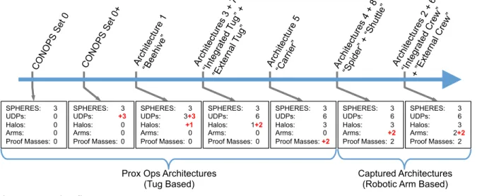
Fig. 9 shows how the incorporation of new hardware to the on-orbit facility can enable further testing that increases the direct traceability of the testbed to future servicing and assembly missions. The most important hardware to be launched is the UDPs, since they allow multi-satellite interactions through both autonomous docking and undocking. The addition of Halo structures enables the testing of dynamic reconfiguration between discrete physical architectures, and the robotic arms enable testing of fully captured architectures across a continually varying physical landscape.
Each increment of Fig. 9 shows how even small gains in hardware can provide significantly increased operational concepts for future flight missions. The required hardware to develop the ISS facility fully can be amortized across multiple mission scenarios so that the hardware delta between scenarios is comparatively small. This process enables technologies to be developed for several CONOPS without the necessity for all hardware to be operational on-orbit at once.
The architecture progression in Fig. 9 demonstrates the versatility of the SPHERES facility on the ISS as a testbed with traceability to many flight CONOPS. Each iteration consists of an assortment of CONOPS in a
SPHERES: 3 UDPs: 0 Halos: 0 Arms: 0 Proof Masses: 0 SPHERES: 3 UDPs: +3 Halos: 0 Arms: 0 Proof Masses: 0 SPHERES: 3 UDPs: 3+3 Halos: +1 Arms: 0 Proof Masses: 0 SPHERES: 3 UDPs: 6 Halos: 1+2 Arms: 0 Proof Masses: 0 SPHERES: 3 UDPs: 6 Halos: 3 Arms: 0 Proof Masses: +2 SPHERES: 3 UDPs: 6 Halos: 3 Arms: +2 Proof Masses: 2 CO NO PS Set 0 CO NO PS Set 0 + Arch itect ure 1 “Be ehive ” Arch itect ure s 3 + 7 “Inte gra ted Tug” + ”Ext ern al T ug” Arch itect ure s 4 + 8 “Sp ider” + “Sh uttle ” SPHERES: 3 UDPs: 6 Halos: 3 Arms: 2+2 Proof Masses: 2 Arch itect ure 5 “Carri er”
Prox Ops Architectures
(Tug Based) Captured Architectures (Robotic Arm Based) Arch itect ure s 2 + 6 “Inte gra ted Cre w” + ”Ext ern al C rew ”
given set. Each set corresponds to a given collection of hardware elements with which researchers can test many individual CONOPS. CONOPS Set 0 represents the current capabilities of the ISS facility, and CONOPS Set 0+ represents the facility should only one UDP be launched per SPHERES satellite. The CONOPS for Architectures 1 through 8 are flexible, although example CONOPS relate closely to those shown in Fig. 2.
1
4
3 2
5 6
Fig. 10: SPHERES implementation of Architecture 1: integrated, distributed, proximity operations
With the UDPs and Halos on station, Architectures 1, 3 and 7 can be tested fairly extensively to quantify metrics. Examples of the CONOPS for these architectures can be found in Fig. 10 through Fig. 12, attempting to mimic those architectures from Fig. 2. Fig. 10 shows the simplest distributed reconfiguration possible with one Halo and six UDPs, where the SPHERES essentially move themselves to different ports to change the system properties without actually manuevering specific modules. Control requirements, response time, and fuel consumption should remain traceable through this CONOPS; however, adding proof masses would improve the results. Fig. 11 and Fig. 12 show centralized reconfiguration where the red Halo-equipped satellite remains passive and is tugged by the orange satellite (integrated and external respectively).
1
4
3 2
5 6
Fig. 11: SPHERES implementation of Architecture 3: integrated, centralized, proximity operations
1
4
3 2
5 6
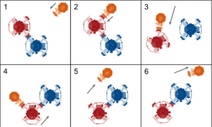
Fig. 12: SPHERES implementation of Architecture 7: external, centralized, proximity operations
Without robotic arms, the facility is limited to testing proximity operations-based architectures that rely on propellant expenditure to manipulate spacecraft elements. These architectures directly expand on the work already conducted on the ground and provide a clear testing path from initial concept to final on-orbit implementation of a flight mission. After the hardware reaches the ISS, the testing described can be executed and important metrics can be evaluated.
V. CONCLUSION
In summary, an architectural tradespace was defined for robotic assembly and servicing missions in terms of three basis vectors or axes: degree of centralization, level of integration, and method of reconfiguration. The resulting eight subspaces were each represented by an extreme design and were compared qualitatively over a set of defined metrics. The SPHERES testbed was used on the ground to begin validation of small steps of the CONOPS for particular architectures. However, in order to fully complete this quantitative validation of metrics, the SPHERES testbed aboard the ISS must be augmented with new hardware. Docking ports and a new multi-port expansion will enable testing of several propulsive, proximity operations architectures. Proof masses and robotic arms are still required to complete the testing of the remaining representative architectures, but have yet to be developed to a flight hardware level.
This paper introduces several areas of future work. First, as discussed throughout the paper, a multi-disciplinary system level design optimization can be performed given the tradespace definition in this paper. This optimization requires quantification of the metrics proposed, and thus validation of that quantification through the planned testing aboard the ISS.
Although out of the scope of the analysis in this paper, defining additional basis vectors to further refine the tradespace is encouraged. The three choices in this paper reflect the authors’ understanding of the most important architecture-level trades, but the space can be
further divided into smaller subspaces given the addition of new basis vectors. For example, the level of human vs. autonomous control in systems is an interesting trade that is not captured in this architecture and could be added as a fourth dimension.
Additionally, a reliable cost model for robotic servicing missions has yet to be developed. Accurately estimating the costs of systems that have not been extensively implemented is very difficult. Without a variety of benchmarking costs and data to collect, a parametric model cannot be statistically dependable.
An important component of successfully validating the metric evaluations is to scale the results found on the described testbeds to full-scale flight systems. This
testbed scaling is ongoing work by the second author30,
but needs further development for implementation in this framework.
Overall, the proposed architecture definition is merely a suggestion, and there may be better definitions available. Testing aboard the ISS and the full system optimization analysis will hopefully give better intuition on whether it should be modified.
ACKNOWLEDGEMENTS
The first author’s research was conducted with Government support under and awarded by DoD, Air Force Office of Scientific Research, National Defense
Science and Engineering Graduate (NDSEG)
Fellowship, 32 CFR 168a.
1 Evans, Cynthia A., et al. "International Space Station Science Research Accomplishments During the Assembly
Years: An Analysis of Results from 2000-2008." (2009).
2 Lillie, Charles F. "On-orbit assembly and servicing of future space observatories." Astronomical Telescopes and
Instrumentation. International Society for Optics and Photonics, 2006.
3 DARPA. 2004. Broad Agency Announcement for Large Aperture Space Surveillance (Optical).
DARPA-BAA-04-36. Defense Advanced Research Project Agency, Tactical Technology Office. Arlington, VA.
4 Dorsey, John T., et al. "Framework for defining and assessing benefits of a modular assembly design approach
for exploration systems." Space Technology and Applications International Forum, 2006. Vol. 813. 2006.
5 Preudschat, A.W. "Satellite Assembly in Geostationary Orbit: A Concept for a Cost Effective Communications
Satellite Applications Platform." 2nd AIAA Conference on Large Space Platforms: Toward Permanent
Manned Occupancy of Space. San Diego, CA. 1981.
6 Hille, Karl and Brian Dunbar. "Hubble Space Telescope: Servicing Missions Overview." NASA. Web. 24 Apr.
2014. Accessed: 29 Aug. 2014. <http://www.nasa.gov/mission_pages/hubble/servicing/>
7 Shoemaker, J., Wright, M., and Sivapiragasam, S., “Orbital Express Space Operations Architecture Program,”
17th Annual AIAA/USU Conference on Small Satellites, SSC03-IV-2, Logan, UT (2003).
8 Sullivan B, Hunter R, Bruhn J, Fowler E, Hoag L, Chappie S, et al. Phoenix Project Status 2013. In: AIAA
SPACE Conference & Exposition, San Diego, CA; 2013. p. 1–17.
9 Reintsema, D., et al., “DEOS – The German Robotics Approach to Secure and De-Orbit Malfunctioned
Satellites from Low-Earth Orbit,” IAC Conference 2012, IAC-12,D1,1,7,x15613, 2012.
10 Gralla, E., and De Weck, O., “Strategies for On-Orbit Assembly of Modular Spacecraft”. JBIS, Vol. 60, 2007.
pp. 219-227.
11 Sullivan, B., “Technical and Economic Feasibility of Telerobotic On-Orbit Satellite Servicing,” PhD.
Dissertation, Department of Aeronautical and Astronautical Engineering, University of Maryland, College Park, MD, 2005.
12 Long, Andrew, Matthew Richards, and Daniel E. Hastings. "On-Orbit Servicing: A New Value Proposition for
Satellite Design and Operation", Journal of Spacecraft and Rockets, Vol. 44, No. 4 (2007), pp. 964-976.
13 Ellery, Alex, Joerg Kreisel, and Bernd Sommer. "The case for robotic on-orbit servicing of spacecraft:
spacecraft reliability is a myth." Acta Astronautica 63.5 (2008): 632-648.
14 Saleh, Joseph H., Elisabeth Lamassoure, and Daniel E. Hastings. "Space systems flexibility provided by
on-orbit servicing: Part 1." Journal of Spacecraft and Rockets 39.4 (2002): 551-560.
15 Flores-Abad, Angel, et al. "A review of space robotics technologies for on-orbit servicing." Progress in
Aerospace Sciences 68 (2014): 1-26.
16 Toglia, C., F. Kennedy, S. Dubowsky, “Cooperative Control of Modular Space Robots,” Autonomous Robots,
In Press, DOI: 10.1007/s10514-011-9238-z. 2011.
17 Barnhart, D. Hill, L., Turnbull, M., & Will, P. “Changing Satellite Morphology through Cellularization”,
18 Ukegawa, K., Natori, M.C., “Concept of self-assembly of space structure systems using autonomous modules,”
54th International Astronautical Congress of the International Astronautical Federation, 29 September - 3 October 2003, Bremen, Germany, IAC-03-U.1.01 (2003).
19 Rodgers, et al. “Concepts and Technology Development for the Autonomous Assembly and Reconfiguration of
Modular Space Systems.” MIT, Space Systems Laboratory #14-05, December 2005.
20 Stroupe, T. Huntsberger, B. Kennedy, H. Aghazarian, E. Baumgartner, A. Ganino, M. Garrett, A. Okon, M.
Robinson, and J. Townsend, "Heterogeneous Robotic Systems for Assembly and Servicing," Proceedings of ISAIRAS 2005.
21 Backes, P.G., K.S. Tso, "Autonomous single arm ORU changeout strategies, control issues, and
implementation”, North- Holland Robotics and Autonomous Systems, 1990.
22 Colombina, G.; Didot, F.; Magnani, G.; Rusconi, A., "Automation and robotics technology testbed for external
servicing," Intelligent Robots and Systems '94. 'Advanced Robotic Systems and the Real World', IROS '94. Proceedings of the IEEE/RSJ/GI International Conference, vol.3, no., pp.1954,1963 vol.3, 12-16 Sep 1994
23 Kawano, I., M. Mokuno, T. Kasai, and T. Suzuki, “Result and Evaluation of Autonomous Rendezvous
Docking Experiments of ETS-VII”, AIAA- 99-4073, AIAA Guidance, Navigation, and Control Conference, Portland, Oregon, August 1999.
24 Rumford, T., “Demonstration of Autonomous Rendezvous Technology (DART) Project Summary”, in Space
Systems Technology and Operations, ed. P. Tchoryk, Jr., and J. Shoemaker, Proceedings of SPIE Vol. 5088, 2003.
25 Galabova, K., G. Bounova, O. de Weck, and D. Hastings, “Architecting a Family of Space Tugs Based on
Orbital Transfer Mission Scenarios”, AIAA 2003-6368. AIAA Space 2003 Conference, Long Beach, CA, 23- 25 September 2003.
26 Rembala, Richard, Cameron Ower, Robotic assembly and maintenance of future space stations based on the
ISS mission operations experience, Acta Astronautica, Volume 65, Issues 7–8, pp. 912-920, Oct-Nov 2009.
27 Akin, D.L., M.L. Bowden, “EVA, robotic, and cooperative assembly of large space structures”, 2002 IEEE
Aerospace Conference Proceedings, 7, Big Sky, Montana, March 2002.
28 Dornheim, M.A., “Orbital Express to Test Full Autonomy for On-Orbit Service”, Aviation Week & Space
Technology, 4 Jun 2006.
29 Zimpfer, D., P. Kachmar, and S. Tuohy, “Autonomous Rendezvous, Capture, and In-Space Assembly: Past,
Present, and Future”, AIAA- 2005-2523, 1st AIAA Space Exploration Conference: Continuing the Voyage of Discovery, Orlando, Florida, January/February 2005.
30 Sternberg, David. “Development of an Incremental and Iterative Risk Reduction Facility for Robotic Servicing
and Assembly Missions.” SM Thesis. Department of Aeronautics and Astronautics, Massachusetts Institute of Technology, Cambridge, MA, 2014.
31 Crawley, E., Sigler, J., and van Schoor, M., “Hybrid Scaled Structural Dynamic Models and Their Use in
Damping Prediction,” AIAA Journal of Guidance, Vol. 13, No. 6, 1990, pp. 1023-1032.
32 Gronet, M., Crawley, E., and Allen, B., “Design, analysis, and testing of a hybrid scale structural dynamic
model of a Space Station,” AIAA Structures, Structural Dynamics and Materials Conference, 30th, Mobile, AL, Apr. 3-5, 1989, Technical Papers. Part 4 (A89-30651 12-39). Washington, DC (1989).
33 Jewison, Christopher. “Reconfigurable Thruster Selection Algorithms for Aggregative Spacecraft Systems.”
SM Thesis. Department of Aeronautics and Astronautics, Massachusetts Institute of Technology, Cambridge, MA, 2014.
34 McCarthy, Bryan. “Flight Hardware Development for a Space-based Robotic Assembly and Servicing
Testbed.” SM Thesis. Department of Aeronautics and Astronautics, Massachusetts Institute of Technology, Cambridge, MA, 2014.