HAL Id: hal-02557231
https://hal.archives-ouvertes.fr/hal-02557231
Submitted on 28 Apr 2020HAL is a multi-disciplinary open access archive for the deposit and dissemination of sci-entific research documents, whether they are pub-lished or not. The documents may come from teaching and research institutions in France or abroad, or from public or private research centers.
L’archive ouverte pluridisciplinaire HAL, est destinée au dépôt et à la diffusion de documents scientifiques de niveau recherche, publiés ou non, émanant des établissements d’enseignement et de recherche français ou étrangers, des laboratoires publics ou privés.
An analysis of the droplet support fiber effect on the
evaporation process
Christian Chauveau, Madjid Birouk, Fabien Halter, Iskender Gökalp
To cite this version:
Christian Chauveau, Madjid Birouk, Fabien Halter, Iskender Gökalp. An analysis of the droplet support fiber effect on the evaporation process. International Journal of Heat and Mass Transfer, Elsevier, 2019, 128, pp.885-891. �10.1016/j.ijheatmasstransfer.2018.09.029�. �hal-02557231�
1
Manuscript Title:
An analysis of the droplet support fiber effect on the evaporation process Authors:
Christian Chauveaua,*, Madjid Biroukb,*, Fabien Haltera,c and Iskender Gökalpa
Affiliations:
a ICARE, CNRS, 1C, Avenue de la Recherche Scientifique, 45071 Orléans Cedex 2, France b Department of Mechanical Engineering, University of Manitoba, Winnipeg, Manitoba, R3T
5V6 Canada
c IUT, Université d’Orléans, 45072 Orléans Cedex 2, France
Corresponding authors:
christian.chauveau@cnrs-orleans.fr madjid.birouk@umanitoba.ca
Journal:
International Journal of Heat and Mass Transfer
Submission date:
2
Abstract
This paper presents an analysis of the effect of the droplet support fiber on the droplet evaporation process. This effect is evaluated for a droplet evaporating in a hot environment at atmospheric pressure using the experimental results of the present study and those in the literature. Selected published results are acquired using similar test conditions and experimental setups as the present data. The only main difference between these studies is the droplet support fiber diameter which varies between 14 µm and 225 µm. The ambient temperature explored in these studies ranges from room temperature up to 973K. n-heptane is selected because it is the most common fuel used in these studies. The main findings are that the cross-fiber technique, which uses 14 µm fiber diameters, induces no noticeable heat transfer into the droplet and consequently does not interfere with the evaporation process. In contrast, the classical fiber technique, which uses relatively larger fibers, greatly enhances the droplet evaporation rate as a consequence of increased conduction heat transfer through the fiber. A correlation is proposed to quantify the level of this increase as a function of ambient temperature and the fiber cross-sectional area, 𝑑𝑓2.
Keywords: Droplet, vaporization, droplet support fiber, high temperature
1. Introduction
The vaporization and combustion of single droplets have been the focus of many studies in the last several decades as a simple approach to gain better understanding of the complex spray combustion phenomena. In fact, a single droplet does not represent a complex spray flow, but it does reveal much of the physics about the evaporation and combustion phenomena which may take place in the diluted spray region farther away from the fuel injector. Consequently, studies of single droplets have undeniably helped advance our understanding of the complex spray combustion phenomena.
Two major approaches were employed for studying experimentally individual droplets, which are the free droplet and the suspended droplet techniques. The former consists of a free-floating/falling droplet injected into a stagnant or a flowing environment. In fact, in this configuration, the droplet is not influenced by any unphysical/external parameter/factor, which makes it the most idealistic method for studying the phenomena of evaporation and combustion of droplets. However, compared to the droplet suspension technique where a fiber is used to hold stationary a droplet, studies employing free droplet are relatively seldom. This is mainly due to the difficulties associated with imaging of a free droplet as it drifts out of the camera focus during its lifetime. For experimental droplet combustion studies, ignition is also a major problem although several classical studies have attempted to overcome these issues (e.g., [1-3]). For instance, several studies used piezoelectric generation techniques to create a stream of droplets which, depending on the inter-droplet spacing, could be considered as a cyclic repetition of an individual droplet (e.g., [4-8]). However, this method requires advanced laser-based sizing techniques to avoid the
3
shortcomings associated with digital imaging equipment [4]. Additionally, the free droplet technique is not suitable for studying its evaporation or combustion in a flowing medium, which is a replica of real spray conditions. That is why, for example, most, if not all studies on droplet evaporation and combustion in different environments, which include laminar and turbulent flow, adopted the suspended droplet technique. The simplicity of this technique in terms of, especially, imaging made it the most practical approach for single droplet studies. Despite its practicality and thus the widespread use of droplet fiber suspension technique, the presence of the fiber induces several artificial effects that alter the droplet evaporation and combustion characteristics. It was reported that using a quartz fiber or a fine thermocouple to suspend a droplet conducts heat into (e.g., [9]) or from (e.g., [10]) the droplet much faster than the surrounding gaseous medium. This consequently makes the findings on droplet evaporation and combustion biased, and the degree of the interference of the fiber depends on the extent of the heat transfer through the suspending fiber.
There exist a large number of published studies which attempted to quantify the impact of the support fiber on the evaporation process of a droplet. For instance, Yang and Wong [11, 12] investigated the impact of the support fiber at a relatively narrow range of ambient temperature (490 – 750 K) and found that increasing the fiber diameter always shortens the droplet lifetime; that is, increases the evaporation process. They also reported that an intermediate fiber diameter may maximize the heat transfer input from the fiber. For example, Yang and Wong [12] found that a quartz fiber of 150 µm in diameter induced a greater heat transfer rate into the droplet compared to a fiber of 300 µm diameter. However, they reported that a droplet suspended onto the 300 µm fiber was found to evaporate faster due to the reduced liquid volume. They then concluded that using a quartz fiber of 50 µm diameter will not affect the evaporation process of a droplet. The experiments and numerical simulations of Han et al. [13] agree that the rate of heat conduction through the fiber increases and then decreases with increasing the suspending fiber diameter. Shringi et al. [14] numerically studied the effect of the support fiber on the evaporation of a droplet in a flow environment at high temperature and pressure conditions. They discovered that while the heat transfer from the gas phase to the droplet surface is initially very high, it rapidly decreases with time as the droplet surface temperature increases. They then remarked that heat transfer through the fiber remains relatively constant, leading to the fiber supplying a significant portion of the droplet’s late stage vaporization energy. They also showed that the droplet suspending fiber can slow down the droplet evaporation process by promoting thermal Marangoni flows near the fiber-droplet contact point, where the circulation of the cooler interior fluid lowers the droplet surface temperature. Recently, Rehman et al. [15] experimentally investigated the effect of heat conduction on the droplet evaporation in a low temperature, forced convection environment. They studied droplets having a diameter ranging between 1565 and 2775 µm in a laminar airflow environment where the temperature was varied between room and 403 K. They varied the suspending fiber diameter and material where glass fibers with diameters ranging between 200 and 800 µm and thermocouples with diameters in the range between 76 and 812 µm were tested. While
4
they found that the suspending fiber technique always increases the vaporization rate, they reported that suspending the droplet on metallic thermocouple wires induces far higher heat transfer by conduction into the droplet and hence results in a higher evaporation rate. Chauveau et al. [16] studied experimentally the evaporation rate of a 800 µm n-decane droplet using the classical suspending technique where quartz fibers with different diameters were tested. They discovered that, when extrapolating the evaporation rate, K, versus the fiber diameter, the theoretical K value that corresponds to a fiber diameter of zero is found identical to the experimentally measured value of the same droplet suspended onto a 14 µm cross-fiber system.
Several studies examined the effect of the suspending/support fiber on droplet combustion using experimental (e.g., [17, 18]) and numerical (e.g., [19]) approaches. It was reported that fibers used for combustion studies can interfere with the droplet burning rate, flame and soot stand-off ratios and flame extinction characteristics. For instance, Mikami et al. [20] used a 14 µm SiC fiber to suspend a droplet in a flame spread experiment and concluded that the effect on the flame shape and heat transfer were much smaller than in the case of a 125 µm quartz fiber. Hicks et al. [18] found experimentally that droplets suspended onto a cross-fiber of 14 µm diameter featured a lower burning rate than the same droplet suspended onto a 110 µm classical quartz fiber with a 360 µm bead. Liu et al. [17] used a 14 µm cross-fiber system for ground-based microgravity tests and compared the results with the same droplet suspended onto a classical 80 µm single fiber. They reported that the droplet suspended onto the cross-fiber exhibited very similar burning characteristics, such as flame and soot stand-off ratios, to free-floating droplets. In contrast, the droplet suspended onto the large fiber tends to distort soot shells near the fiber droplet intersection.
It is important to mention that if the support fiber is to improve the evaporation rate, the effect is most likely to be witnessed towards the end of the droplet lifetime. This is exactly what is observed when using the classical fiber suspending technique where the d2-law does not hold towards the
end of the droplet lifetime; that is, a clear acceleration of the temporal variation of d2 can be witnessed (e.g., [15]). This, of course, is not the case when using the cross-fiber technique (e.g., [21, 22]) where tiny fibers are used. In this case, the 𝑑2-law tends to hold until the complete
depletion of the liquid or at least such an acceleration does not manifest (e.g., [21, 22]).
This brief discussion of the literature clearly reveals the influence of the suspending technique on the evaporation and combustion processes of a droplet. Thus, the objective of the present paper is to analyze such an impact by quantifying the additional increase in the droplet evaporation rate due to the heat conduction through the suspending fiber. Due to limited published experimental data, only available results in stagnant environment at standard ambient pressure are analyzed where the effect of droplet diameter is also omitted in the present investigation.
5
The experimental set-up is well documented elsewhere [23,24], and thus, only a brief description is provided here. The experimental test facility consists mainly of a furnace and the droplet support and formation system. The furnace is essentially a short cylinder with an inner diameter of 68 mm and a height of 100 mm, which produces a volume of 360 cm3. The furnace is capable of attaining
a temperature of up to 1200 K, generated by a Joule effect heater placed in a pressure chamber that envelops the furnace. The droplet, which is suspended at the intersection of a cross-fiber system, is formed by injecting the liquid fuel using a piezo-electric injection system. The cross-fiber consists of two quartz fibers each having a diameter of 14 µm and fixed perpendicularly using a metallic frame system. n-heptane (C7H16) is chosen as the liquid because it is intensively used in
the literature and consequently makes possible to perform comparisons with published data. In order to avoid oxidation at high temperatures, nitrogen is selected as the furnace gaseous medium surrounding the suspended droplet. The droplet is initially formed in the lower section of the chamber and then introduced into the furnace by the aid of a motorized displacement system. Once the droplet is exposed to the hot atmosphere in the furnace, the temporal regression of the projected droplet surface area is recorded using a high-speed video camera with a frame rate that can be varied between 150 and 750 fps depending on the test conditions. For each experiment, approximately 700 images are recorded in order to achieve a satisfactory temporal dynamics. In addition, at least five experiments are performed for each test conditions to verify the repeatability of the results as well as to minimize statistical errors. The images are analyzed via post-processing to deduce the droplet instantaneous projected surface area and hence the time variation of its squared equivalent diameter. Note that the involved error in determining the droplet diameter is found around 3%. For instance, the droplet evaporation rate at T = 973K is found around 0.296 mm2/s with a standard deviation of 1.2%. Two series of droplet vaporization experiments are carried out in the present study; one in normal gravity, and another in microgravity conditions of 10-2g0. The latter are realized via parabolic flights aboard of the A300 Aircraft of CNES, the French
National Space Agency. Note that each microgravity period lasts approximately 22 seconds. In both series of experiments, the pressure in the furnace is kept atmospheric, while the ambient temperature is varied in the range between 473K and 748K for microgravity experiments, and between 473K and 973K for normal gravity experiments. The droplet diameter is maintained around 370 µm for microgravity experiments and around 500 µm for normal gravity experiments.
Additional experiments at standard atmospheric pressure are performed to acquire data at the lower end of the ambient temperature in normal gravity conditions; that is, between approximately 300 K and 473 K using the test rig at the University of Manitoba. Detailed description of this experimental setup is reported elsewhere [21, 22]. Essentially, the thermally-insulated spherical chamber has 2-pair of large windows arranged along the horizontal equator. Heat is transferred by convection into the nitrogen gaseous medium inside the chamber via a heating coils system installed in one of the window ports. The heating coils switch on and off as a means of temperature control until the nitrogen has reached the required temperature, which remained constant across
6
the horizontal mid-plane of the chamber. The chamber is filled with commercial dry nitrogen and is held to ±1% of the nominal pressure by monitoring the transducer output. The chamber is thoroughly vacuumed before the filling process to remove any accumulated moisture and impurities from the ambient gas. n-heptane droplet is deposited onto the intersection point of two 14-µm silicon carbide fibers, which are supported by an aluminum frame. Droplet evaporation is captured in 8-bit grayscale of a high-speed NanoSense MkIII camera with a 250 W backlight at a frame rate ranging up to 100 fps. An in-house developed MATLAB code is then used to post process the images and determine the temporal d2 profile. The droplet evaporation rate is determined as 𝐾 = −(𝑑2)/𝑑𝑡 and found repeatable to ± 2%.
3. Results and Discussion
3.1. General comments
The influence of the suspension fiber on droplet evaporation was reported in our previous studies [23, 24]. In these studies, n-decane was used to form an individual droplet with an initial diameter of around d0 = 800 µm in a nitrogen hot environment at 570 K and 0.1 MPa. The diameter of the
cross-fiber was 𝑑𝑓=14 µm and the diameter of the classical single suspending fiber was varied between 𝑑𝑓=106 µm and 181 µm. The experimental results showed a linear variation between the droplet evaporation rate and the fiber cross-sectional area, expressed in terms of 𝑑𝑓2. This relation revealed that the droplet evaporation rate increases linearly with the fiber cross sectional area, 𝑑𝑓2. An extrapolation of the linear variation to 𝑑𝑓2 = 0 showed that there is no difference in the evaporation rate between the case when using the 14 µm cross-fiber and the theoretical case, that is, without a fiber (i.e., 𝑑𝑓2 = 0). This suggests that using a cross-fiber system with very small dimensions (e.g., around 14 µm) does not conduct any noticeable heat transfer between the droplet and its surroundings and consequently does not interfere with the evaporation process. However, this result and that reported in the next sections show that the droplet evaporation rate increases with the fiber size and becomes more pronounced as the ambient temperature increases.
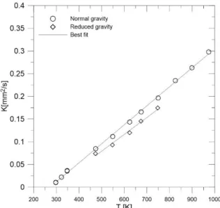
This finding led to believe that the abundant experimental data available in the open literature and reporting on the evaporation process obtained using large droplet suspending fibers may be questionable. Consequently, the analysis presented below attempts to quantify the extent of this impact at ambient atmospheric pressure and different temperatures. In doing so, and since most of the available published measurements were performed with n-heptane at atmospheric and elevated pressure, the present analysis was carried out using the same fuel but at only atmospheric pressure conditions. In order to develop data on the evaporation of n-heptane droplet using the cross-fiber technique at different ambient temperatures, further experiments were carried out using the setups described in the previous section. These experiments were performed at normal gravity and also at reduced/microgravity gravity. The collected results are depicted in Figure 1. As expected, this figure shows a linear increase of the evaporation rate with the ambient temperature, and the
7
evaporation rate in normal gravity is slightly greater than in reduced gravity. This is expected since natural convection prevails under normal gravity conditions.
Since the majority of published measurements are more abundant under normal gravity, the bulk of the analysis presented here is performed at this condition. However, the limited data at microgravity test conditions is also presented separately.
3.2. Experiments under normal gravity conditions
To analyze the influence of the droplet suspending fiber on the evaporation rate, the experimental data at normal gravity, reported in Fig. 1, is compared with published results obtained under similar conditions. The selected published studies [25-29] feature similar experimental setups where n-heptane (common for all these studies) droplets are generated in an atmosphere and suspended at the tip of a quartz fiber, which is subsequently introduced into a furnace at high temperature, either by displacement of the support into the furnace, or by the displacement of the furnace itself so that the droplet becomes exposed to a hot nitrogen gaseous medium inside the furnace. The dimensions of the furnaces used in these studies including those in [23, 24] are similar. This approach makes it possible to assume that the effect of the liquid-phase absorption of the radiation from the furnace walls would be similar for all the studies and thus assumed to have no influence on the differences observed between the analyzed results. Therefore, the major differences between these studies consist of the diameter of the droplet support fiber and to a less extent the initial size of the droplet. However, the effect of droplet size under the test conditions explored in these studies is considered negligible. Verwey and Birouk [21, 22] demonstrated that the evaporation rate of n-heptane droplets, ranging between approximately 300 and 800 µm, changes only at elevated ambient pressure or in convective flow environments or both combined, while it remains nearly constant at standard ambient pressure. Morin [30] also demonstrated that, within her explored range of droplet sizes (810 and 1330 µm), the evaporation rate in a hot environment remains practically constant at ambient atmospheric pressure. Even if the influence of the droplet initial diameter is not to be neglected at the conditions explored here, it is believed to be less critical than that of the size of the droplet support system, as it conditions mainly the duration of the droplet pre-heating phase and the influence of the liquid-phase radiative absorption. The test conditions of these studies are summarized in Table 1.
Figure 2 presents a comparison of the normalized temporal evolution of the squared diameter of n-heptane droplets between the present data in normal gravity and the experimental data of Nomura et al. [25] under microgravity conditions. This figure clearly shows that the temporal variation of the normalized squared diameter of n-heptane droplets suspended on the cross-fiber is linear and extends till the complete depletion of the liquid at nearly 𝑑2/𝑑02 = 0. However, in the case of the classical fiber technique [25], the liquid droplet depletes much earlier and the evolution of 𝑑2/𝑑
0 2
8
Nomura et al. [25] despite the fact that natural convection is suppressed. This is a clear indication of the influence of the size of the droplet support fiber on the evaporation process.
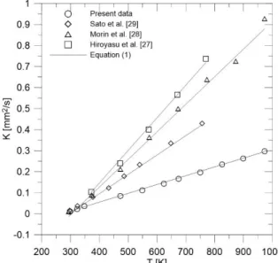
These observations are confirmed by observing the evolution of the vaporization rate as a function of the ambient temperature in Figure 3. In this figure, in addition to the present experimental data depicted in Figure 1 under normal gravity conditions, available published experimental results are also displayed for comparison. Independently of the influence of the natural convection for all of these studies performed under normal gravity conditions, this figure shows clearly that the present cross-fiber experiment exhibited the lowest evaporation rate. Note that the diameter of the support fiber is 225 µm, 200 µm, 150 µm, 125 µm, and 14 µm for Hiroyasu et al. [27], Morin et al. [28], Sato et al. [29], Ghassemi et al. [26] and the present cross-fiber study, respectively. The effect of the size of the support fiber is apparent in this figure; where, at any given temperature, it shows that, at the same test conditions, the larger the support fiber size, the greater is the droplet vaporization rate. This ascertains the importance of the effect of heat conduction through the support fiber, which engenders an increase in the droplet evaporation rate. This figure shows also that enhancement in the evaporation rate becomes more pronounced with increasing ambient temperature. For instance, at 400 K, the increase in the droplet evaporation rate with respect to the cross-fiber case is around 77, 138 and 174% for 𝑑𝑓 = 150, 200 and 225 µm, respectively; while at 800 K, this increase is, respectively, about 100, 197 and 249%. This suggests that the rate of heat conduction through the fiber increases with ambient temperature.
The numerical results of Yang and Wong [11] and Ebrahimian and Habchi [31] are also included in Figure 3 for comparison. These numerical results are obtained by ignoring the heat transfer through the droplet suspending fiber [11] or excluding completely the fiber [31]. While the numerical results of Ebrahimian and Habchi [31] are in agreement with the present cross-fiber experimental data; those of Yang and Wong [11] are higher by about 17% to 20% depending on the ambient temperature. This is beside the fact that the present data is acquired under normal gravity which induces natural convection and consequently increases the droplet evaporation rate. Nevertheless, while the causes of these differences are unknown, all these numerical results corroborate the conclusion that the classical/conventional droplet support fiber alters the evaporation process.
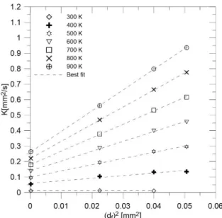
The results presented in Figure 3 suggest that there exists an increasing linear relation between the enhancement in the droplet evaporation rate associated with the heat transfer through the support fiber and the fiber size. The fiber size in this case is expressed in terms of the fiber cross-sectional area, that is 𝑑𝑓2, as was reported in [15, 23, 24] and will be justified later on. A plot of this data revealed that a correlation between the experimental evaporation rate and the support fiber diameter cross-sectional area 𝑑𝑓2 at different ambient temperatures can be expressed as follows:
9
𝐾(𝑇) = 𝐶𝐷𝑓(𝑇) × 𝑑𝑓2+ 𝐾0(𝑇) (1)
where 𝐾0(𝑇) is the idealized evaporation rate without the influence of heat conduction through the fiber, which is obtained by extrapolating the linear variation to 𝑑𝑓2 = 0, and 𝐶𝐷𝑓(𝑇) is the slope of the linear variation of the droplet evaporation rate 𝐾(𝑇) as a function of the squared diameter of the support fiber. Both these parameters, which are a function of the ambient temperature, are determined at each ambient temperature using the data in Figure 4. It is important to mention that this figure shows a clear linear relationship between 𝐾(𝑇) and 𝑑𝑓2 and consequently allows determining reliable values of 𝐾0(𝑇) and 𝐶𝐷𝑓(𝑇). In this Equation, 𝐾(𝑇), 𝐶𝐷𝑓(𝑇), 𝐾0(𝑇) and 𝑑𝑓2
are expressed in [mm2/s], [s-1], [mm2/s] and [mm2], respectively.
The linear evolution of Equation (1) can be justified as follows. Due to the relatively small diameter of the fiber, the conduction heat flux propagating through the fiber can be considered as mono-dimensional. This means that the heat flux is proportional to the cross sectional area of the fiber and consequently to 𝑑𝑓2. On the other hand, the vaporization rate 𝐾(𝑇), in Figure 3, varies linearly with the ambient temperature, as confirmed experimentally and theoretically. Since the heat flux, within the context of the quasi-steady theory, is proportional to the difference between the ambient temperature and the droplet surface temperature as (𝑇 - 𝑇𝑠) where the surface temperature 𝑇𝑠 is approximately constant, the vaporization rate would vary linearly with the heat flux.
The variations of 𝐾0(𝑇) and 𝐶𝐷𝑓(𝑇) as a function of the ambient temperature are expressed by Eqs. (2-3) and presented in Figure 5. In this figure, the data of the droplet evaporation rate obtained using the cross-fiber technique is also displayed for comparison. Both 𝐾0(𝑇) and 𝐶𝐷𝑓(𝑇) display a perfect linear relationship with the ambient temperature. Also, this figure clearly shows that the value of 𝐾0(𝑇) (theoretical which corresponds to 𝑑𝑓 = 0) is practically identical to that obtained with the cross fiber technique where the data of the two methods appears to overlap. This implies that the cross-microfiber configuration does not lead to biased evaporation process, and thus corroborate the conclusion reported in [16].
𝐾0(𝑇) = 4.1434 × 10⁻⁴× 𝑇[𝐾] − 0.1078 (2)
𝐶𝐷𝑓(𝑇) = 2.2723 × 10⁻²× 𝑇[𝐾] − 7.1744 (3)
The proposed correlation (Eq. (1)) is examined by comparing its predictions with the experimental data points of the studies reported in Fig. 3 and Table 1, and plotted in Fig. 6. This figure shows very good agreement between the predictions of Equation (1) and the experimental data. This correlation is very useful as one can use it to make corrections of experimental data collected using
10
large fibers. It can also serve as a guideline for numerical simulations in order to develop high fidelity simulation codes.
3.3. Experiments under microgravity conditions
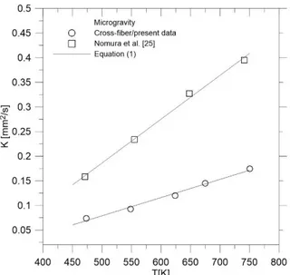
As mentioned earlier, there exist only few experimental data in microgravity conditions reporting on the evaporation of single droplets, as the bulk of published results are acquired in normal gravity conditions. The present experimental results in microgravity conditions are plotted in Figure 7 along with their published counterparts of Nomura et al. [25]. The present and Nomura et al. [25] experimental data is obtained using similar experimental setups as highlighted above with the exception of the diameter of the droplet suspending fiber, which is about 11 times larger in the experiments of Nomura et al. [25]. Table 2 summarizes the test conditions of the data depicted in Figure 7. Since the effect of natural convection is suppressed in microgravity, the correlation presented in Eq. (1) may not apply in this condition because of the difference in the droplet evaporation rate as observed in Fig.1. Therefore, the values of 𝐾0(𝑇) and 𝐶𝐷𝑓(𝑇) at each ambient
temperature in microgravity conditions are determined using a similar approach to that followed in the case of normal gravity which is presented in Fig. 4. Consequently, the expressions of these two parameters in microgravity are estimated as follows:
𝐾0(𝑇) = 3.6552 × 10⁻⁴× 𝑇[𝐾] − 0.1078 (4)
𝐶𝐷𝑓 (𝑇) = 2.3304 × 10⁻²× 𝑇[𝐾] − 6.8437 (5)
As shown in Fig.7, when 𝐾0(𝑇) and 𝐶𝐷𝑓(𝑇) are determined using Eqs. (4-5), respectively, Eq. (1) is capable of predicting well the experimental data of the cross-fiber technique as well as that of the large classical fiber used by Nomura et al. [25]. It is interesting to remark that, although Eqs. (4-5) are derived based on only the data reported in Table 2, Eq. (1) could still work well for different fiber sizes. This is due to the fact that the relationship between the experimental droplet evaporation rate and the fiber squared diameter may remain linear as in the case of normal gravity (Fig. 4). However, this generalization of the application of this equation over a much wider range of fiber size is still to be confirmed in microgravity conditions.
4. Final remarks and conclusions
The present study examined the influence of the size of the droplet suspending fiber on the evaporation process in normal and microgravity conditions at standard pressure. The analysis carried out here was based on the experimental results of droplet evaporation obtained using the cross-fiber technique employed in the present paper and other published results acquired using larger classical fibers. The comparison between these experimental results was made possible by
11
selecting published data obtained under nearly identical test conditions with the exception of the size of the droplet support fiber and to a less extent the droplet initial diameter.
The analysis carried out in this study is useful as it clearly shows that the effect of the suspension fiber is very important and can even hinder the benefit of the simplicity of the classical suspending fiber technique as well as the abundant published experimental data using this technique. The present results and those reported in [23, 24] confirmed that the evaporation rate when suspending a droplet onto a cross-fiber made of 14 µm is nearly identical to that corresponding to the case without the presence of a fiber. This suggests that this technique does not influence the droplet evaporation process.
More importantly, the analysis carried out in this study allowed quantifying the impact of heat transfer by conduction through the fiber and consequently the increase in the vaporization rate due to the presence of the support fiber. A correlation is developed expressing this increase in the droplet evaporation rate as a function of the squared diameter of the droplet suspending fiber. This correlation can be used to revisit available published experimental results. However, while the proposed correlation is a step forward, it still has several limitations where the extent of the impact of the fuel type and droplet size still needs further studies. For instance, an analysis of the relationship between the fiber size and the droplet evaporation rate of n-heptane and the limited data of n-decane reported in [23-34] revealed a greater influence of the fiber on the more volatile liquid fuel. Also, it would be interesting to revisit published studies carried out regarding the effect of ambient pressure on the droplet evaporation, since all these experiments were conducted with fibers having large sizes, which induce systematic over-estimation of the measured evaporation rates. Such a task will however be challenging since, in addition to the effect of the fiber, pressure intensifies natural convention at normal gravity conditions in which the effect of droplet size becomes critical.
Acknowledgements
This research was supported by the Centre National d’Etudes Spatiales (CNES) and the Centre National de la Recherche Scientifique (CNRS). The visit of Professor Birouk to ICARE was partly supported by the University of Manitoba (research leave), The University of Orleans (visiting professor), and the CAPRYSSES project (ANR- 11-LABX-006–01) funded by ANR through the PIA (Programme d’Investissement d’Avenir).
References
[1] G.S. Jackson, C.T. Avedisian, The effect of initial diameter in spherically symmetric droplet combustion of sooting fuels, Proc. R. Soc. London A. 446 (1994) 255–276.
12
[2] S. Kumagai, T. Sakai, S. Okajima, Combustion of free fuel droplets in a freely falling chamber, Symp. Combust. 13 (1971) 779–785.
[3] H. Hara, S. Kumagai, The effect of initial diameter on free droplet combustion with spherical flame, Symp. Combust. 25 (1994) 423–430.
[4] D. Nguyen, D. Honnery, J. Soria, Measuring evaporation of micro-fuel droplets using magnified DIH and DPIV, Exp. Fluids. 50 (2011) 949–959.
[5] G. Castanet, P. Lavieille, F. Lemoine, M. Lebouché, A. Atthasit, Y. Biscos, G. Lavergne, Energetic budget on an evaporating monodisperse droplet stream using combined optical methods: Evaluation of the convective heat transfer, Int. J. Heat Mass Transf. 45 (2002) 5053–5067.
[6] C. Maqua, G. Castanet, F. Lemoine, Bicomponent droplets evaporation: Temperature measurements and modelling, Fuel. 87 (2008) 2932–2942.
[7] T. Kristyadi, V. Deprédurand, G. Castanet, F. Lemoine, S.S. Sazhin, A. Elwardany, E.M. Sazhina, M.R. Heikal, Monodisperse monocomponent fuel droplet heating and
evaporation, Fuel. 89 (2010) 3995–4001.
[8] D. Honnery, D. Nguyen, J. Soria, Microdroplet evaporation under increasing temperature conditions: Experiments and modelling, Fuel. 105 (2013) 247–257.
[9] G.O. Langstroth, C.H.H. Diehl, E.J. Winhold, The evaporation of droplets in still air, Can. J. Res. 28A (1950) 580–595.
[10] S. Kumagai, T. Sakai, S. Okajima, Combustion of free fuel droplets in a freely falling chamber, Symp. Combust. 13 (1971) 779–785.
[11] J.-R. Yang, S.-C. Wong, On the discrepancies between theoretical and experimental results for microgravity droplet evaporation, Int. J. Heat Mass Transf. 44 (2001) 4433–4443. [12] J.-R. Yang, S.-C. Wong, An experimental and theoretical study of the effects of heat
conduction through the support fiber on the evaporation of a droplet in a weakly convective flow, Int. J. Heat Mass Transf. 45 (2002) 4589–4598.
[13] K. Han, G. Song, X. Ma, B. Yang, An experimental and theoretical study of the effect of suspended thermocouple on the single droplet evaporation, Appl. Therm. Eng. 101 (2016) 568–575.
[14] D. Shringi, H.A. Dwyer, B.D. Shaw, Influences of support fibers on vaporizing fuel droplets, Comput. Fluids. 77 (2013) 66–75.
[15] H.L. Rehman, J. Weiss, P. Seers, Effect of heat conduction on droplet life time and evaporation under forced convection at low temperatures, Exp. Therm. Fluid Sci. 72 (2016) 59-66.
[16] C. Chauveau, M. Birouk, I. Gökalp, An analysis of the d2-law departure during droplet evaporation in microgravity, Int. J. Multiph. Flow. 37 (2011) 252–259.
13
[17] Y.C. Liu, Y. Xu, C.T. Avedisian, M.C. Hicks, The effect of support fibers on
micro-convection in droplet combustion experiments, Proc. Combust. Inst. 35 (2015) 1709–1716. [18] M.C. Hicks, V. Nayagam, F.A. Williams, Methanol droplet extinction in
carbon-dioxide-enriched environments in microgravity, Combust. Flame. 157 (2010) 1439–1445. [19] T. Farouk, F.L. Dryer, Microgravity droplet combustion: Effect of tethering fiber on
burning rate and flame structure, Combust. Theory Model. 15 (2011) 487–515. [20] M. Mikami, H. Oyagi, N. Kojima, M. Kikuchi, Y. Wakashima, S. Yoda, Microgravity
experiments on flame spread along fuel-droplet arrays using a new droplet-generation technique, Combust. Flame. 141 (2005) 241–252.
[21] C. Verwey, M. Birouk, Experimental investigation of the effect of natural convection on the evaporation characteristics of small fuel droplets at moderately elevated temperature and pressure, Int. J. Heat Mass Transf. 118 (2018) 1046-1055.
[22] C. Verwey, M. Birouk, Experimental investigation of the effect of droplet size on the vaporization process in ambient turbulence, Combust. Flame 182 (2017) 288-297. [23] F. Renaud, C. Chauveau, I. Gokalp in: On the effects of supporting fibers and natural
convection on fuel droplet vaporization, 19th Annual Conference on Liquid Atomization and Spray Systems (ILASS-Europe'04), Nottingham, 6th-8th September, pp 475-480, 2004.
[24] C. Chauveau, M. Birouk, I. Gökalp, An analysis of the d²-law departure during droplet evaporation in microgravity, Int. J. Multiph. Flow, 73 (2011) 252-259.
[25] H. Nomura, Y. Ujiie, H.J. Rath, J.i. Sato, M. Kono, Experimental study on high-pressure droplet evaporation using microgravity conditions, Proc. Combust. Inst., 26, 1267-1273, 1996
[26] H. Ghassemi, S.W. Baek, Q.S. Khan, Experimental study on binary droplet evaporation at elevated pressures and temperatures, Combust. Sci. Technol., 178, (6), 1031-1053, 2006. [27] H. Hiroyasu, T. Kadota, T. Senda, T. Imamoto, Evaporation of a Single Droplet at
Elevated Pressures and Temperatures: Part 1, Experimental Study, Transactions of the Japan Society of Mechanical Engineers, 40, (339), 3147-3154, 1974.
[28] C. Morin, C. Chauveau, I. Gokalp, Droplet vaporisation characteristics of vegetable oil derived biofuels at high temperatures, Exp. Thermal Fluid Sci., 21, (1-3), 41-50, 2000. [29] J. Sato, Studies on droplet evaporation and combustion in high pressures, 31st Aerospace
and Science Meeting and Exhibition, January 11-14, 1993, Reno, NV, Paper: AIAA93-0813.
[30] C. Morin, Vaporization and oxidation a haute temperature et haut pression de gouttes de combustibles liquids. Application aux n-alcanes et esters methyliques d’huiles vegetales, PhD thesis, University of Orleans, France.
14
[31] V. Ebrahimian and C. Habchi, Towards a predictive evaporation model for
multi-component hydrocarbon droplets at all pressure conditions, Int. J. Heat Mass Transf., 54, 3552-3565, 2011.
15
Tables
Table 1. Normal gravity test conditions
T [K] d0 [µm] df [µm] Reference 300-997 550-800 14 Present study 293-756 600-800 150 Sato et al. [29] 673-997 1100-1300 125 Ghassemi et al. [26] 373-773 1000 225 Hiroyasu et al. [27] 293-997 810-1330 200 Morin et al. [28]
Table 2. Microgravity test conditions
T [K] d0 [µm] df [µm] Reference
473-748 370 14 Present study 471-750 600-800 150 Nomura et al. [25]
16
Figures
Fig. 1. Variation of the evaporation rate of n-heptane droplets with the ambient temperature in
normal or reduced/microgravity conditions.
Fig. 2. Comparison of n-heptane droplet lifetimes between the present study in normal gravity and
17
Fig. 3. Comparison of the evaporation rate of n-heptane droplets between the results of the present
study and some published experimental and numerical results.
Fig. 4. Evolution of the evaporation rate of n-heptane droplets as a function of the squared diameter
18
Fig. 5. Variation of the coefficient 𝐶𝐷𝑓versus the ambient temperature, and a comparison between the idealized evaporation rate of n-heptane droplets and the results with the cross-fiber.
Fig. 6. Comparison of the experimental evaporation rate of n-heptane droplets with the predictions
19
Fig. 7. Comparison of the experimental evaporation rate of n-heptane droplets with the predictions
![Table 1. Normal gravity test conditions T [K] d 0 [µm] d f [µm] Reference 300-997 550-800 14 Present study 293-756 600-800 150 Sato et al](https://thumb-eu.123doks.com/thumbv2/123doknet/14370077.504215/16.918.110.525.209.344/table-normal-gravity-conditions-reference-present-study-sato.webp)