HAL Id: hal-00806083
https://hal.archives-ouvertes.fr/hal-00806083
Submitted on 29 Mar 2013
HAL is a multi-disciplinary open access
archive for the deposit and dissemination of
sci-entific research documents, whether they are
pub-lished or not. The documents may come from
teaching and research institutions in France or
abroad, or from public or private research centers.
L’archive ouverte pluridisciplinaire HAL, est
destinée au dépôt et à la diffusion de documents
scientifiques de niveau recherche, publiés ou non,
émanant des établissements d’enseignement et de
recherche français ou étrangers, des laboratoires
publics ou privés.
Magnetic and semi-conducting nano-composite films of
spinel ferrite and cubic zinc oxide
Lionel Presmanes, Stéphanie Capdeville, Corine Bonningue, Lucien Datas,
Philippe Tailhades
To cite this version:
Lionel Presmanes, Stéphanie Capdeville, Corine Bonningue, Lucien Datas, Philippe Tailhades.
Mag-netic and semi-conducting nano-composite films of spinel ferrite and cubic zinc oxide. Thin Solid
Films, Elsevier, 2007, vol. 515, pp. 6676-6681. �10.1016/j.tsf.2007.01.006�. �hal-00806083�
O
pen
A
rchive
T
oulouse
A
rchive
O
uverte (
OATAO
)
OATAO is an open access repository that collects the work of Toulouse researchers and
makes it freely available over the web where possible.
This is an author-deposited version published in:
http://oatao.univ-toulouse.fr/
Eprints ID : 2429
To link to this article :
URL :
http://dx.doi.org/10.1016/j.tsf.2007.01.006
To cite this version :
Presmanes, Lionel and Capdeville, S. and Bonningue, Corine
and Datas, L. and Tailhades, Philippe ( 2007)
Magnetic and semi-conducting
nano-composite films of spinel ferrite and cubic zinc oxide.
Thin Solid Films, vol.
515 (n° 17). pp. 6676-6681. ISSN 0040-6090
Any correspondence concerning this service should be sent to the repository
administrator: staff-oatao@inp-toulouse.fr
Magnetic and semi-conducting nano-composite films
of spinel ferrite and cubic zinc oxide
L. Presmanes, S. Capdeville, C. Bonningue, L. Datas, Ph. Tailhades
⁎
CIRIMAT, UMR CNRS 5085, Université Paul Sabatier, 118 route de Narbonne, 31 062 Toulouse Cedex 4, FranceAbstract
Magnetic and semi-conducting nano-composite films have been prepared under bias polarization, by radio-frequency sputtering of a pure zinc ferrite target. These composite thin films are made of cubic Zn1− yFeyO monoxide islands inside a spinel ferrite matrix. The relative proportion of
each phase depends on the substrate polarization (i.e. bias power). When no bias is applied the films solely display the diffraction pattern of a spinel phase even if some islands inside the film can be observed by electron microscopy. When the bias power is increased, the spinel phase disappears progressively as enhanced formation of islands takes place in such a manner that the cubic Zn1− yFeyO monoxide is solely revealed by
X-ray diffraction for a bias power higher than 5 W. From bibliographical data and calculated phase diagrams, it can be inferred that these phases would require very low oxygen partial pressure, high temperature and mechanical pressure, to be obtained simultaneously by a conventional ceramic process. This underlines the strong potential of radio-frequency sputtering of oxide targets to prepare original oxides or composite materials.
Keywords: Zinc oxide; Ferrite; Sputtering; Nano-composites; Thin films
1. Introduction
Original or enhanced properties at room temperature can be induced in out-of-equilibrium or non-stoichiometric oxides. The preparation of this type of material is interesting for technological applications (optical recording media, magnetic devices, sensors, etc.). One of the challenges, however, is to get the required properties with systems compatible with the materials of the technological environment in which they have to be used. These systems have then to be both prepared at quite low temperature and easily integrated in complex devices or circuitry.
Radio-frequency (RF) sputtering is a method which allows film preparation at quite low temperatures, making it possible to deposit various materials on different substrates, such as glass or silicon which are not stable at high temperature. It is one of the main reasons this process is widely used to prepare and combine different types of materials for optical, magnetic or electronic
applications. But the interest of RF sputtering is also that it offers the possibility of preparing different materials, especially oxides, which can be out-of-equilibrium or non-stoichiometric at room temperature[1,2].
During sputtering of an oxide target, the layer grown on the substrate is submitted to continuous bombardment with high energy species coming from plasma and target, which can induce specific characteristics or properties[3–5]. Light atoms, such as oxygen, can be specially ejected from the film leading to reducing conditions [4,6] and hence the formation of non-stoichiometric oxides. The bombardment can also stabilize metastable oxides because it also acts upon the mechanical stress and microstructure of the films. Many substituted and metastable spinel ferrites have already been obtained by sputtering a mixed ferrite target[5,7,8].
In this paper, the versatility of radio-frequency sputtering is used to prepare various magnetic and semi-conducting composites made of spinel ferrites and zinc oxides, materials which are the subject of a large number of works for potential spintronic devices[9–11].
⁎ Corresponding author.
E-mail address:tailhade@chimie.ups-tlse.fr(Ph. Tailhades).
2. Experimental details 2.1. Target preparation
Target preparation consisted in sintering an α-Fe2O3+
ZnFe2O4 mixture obtained by decomposition of an oxalate
precursor. In order to obtain a stoichiometric spinel, the target was heated under nitrogen flow. The sintering temperature was set at 960 °C. X-ray diffraction patterns showed a pure spinel phase. The chemical composition Zn0.87Fe2.13O4 was
deter-mined by plasma emission spectroscopy. 2.2. Thin film deposition
Thin film deposition was carried out on conventional glass slides for optical microscopy (35 × 25 × 1 mm3or 35 × 25 × 0.15 mm3). The previous ceramic target was sputtered in an Alcatel CIT A450 RF machine working in diode configuration with a radio frequency of 13.56 MHz. In this machine, the target is above and parallel to the substrate. A residual vacuum of 5.10−5 Pa was reached in the sputtering chamber before admitting the deposition gas (argon). The distance between the target and the substrates was fixed at 50 mm, the gas pressure was 0.5 Pa and the power density was 2.5 W/cm2. Four bias powers (0; 2.5; 5 and 10 W) were used. The film composition, determined by a Cameca SX50 electron microprobe, was very close to the nominal composition of the target when no bias power was applied. Bias sputtered films displayed slightly lower zinc contents.
2.3. Characterizations
Film thicknesses were measured using a Dektak 3030ST profilometer. Structural characterizations were performed by grazing angle X-ray diffraction on a Siemens D5000 diffrac-tometer. This apparatus was equipped with a copper anticathode and a SiLi detector. Because of their low thickness and poor crystallization, the films were studied using a step scan of 0.02° and a step time of 18 s. The chemical composition of the samples was determined by a Cameca SX50 electron micro-probe. To study the microstructure of as-deposited samples,
scanning electronic microscopy with field effect gun (FEG-SEM) and atomic force microscopy observations were carried out with a JEOL JSM 6700F (operating at 10 kV) and a Veeco D3000 (in tapping mode, with a Nanosensors NCH-50 tip) respectively. A JEOL JEM 2100F transmission electronic microscope with field effect gun (FEG-TEM) operating at 200 kV was used to provide high-resolution images. We measured the Zn/Fe atomic ratio in different regions of the film by X-ray analysis with a PGT energy dispersive system. The spot size of the electron beam had a diameter of 1 nm. For FEG-TEM observations and analysis, 50 nm thick film of ferrite were directly sputter-deposited on a Carbon/Formvar grid. Freshly prepared samples were observed to avoid contamination and topographical surface changes. Magnetic measurements were done with a Superconducting Quantum Interference Device (SQUID) magnetometer MPMS Quantum design 5.5 on samples deposited on both sides of a 4.5 × 4.5 × 0.15 mm3 glass substrate. The phase diagram in the Zn–Fe–O system was calculated with the FactSage™ v5.3 software (developed by Thermfact/CRCT and GTT-Technologies).
3. Results and discussion
As-deposited films prepared on substrates biased with 5 W power were studied first. These films are poorly crystallized as revealed by X-ray diffraction. In spite of the spinel structure of the ceramic target and its stoichiometry (metallic cation/oxygen anion ratio equal to 3/4), their diffraction pattern is ascribed to a cubic monoxide with a rock-salt structure, which will be written Zn1− yFeyO in this study, considering iron cations can partly
substitute zinc cations (Fig. 1). Atomic force microscopy reveals a bimodal grain size distribution (Fig. 2). About 10% of the film area is made up of grains with a mean diameter centred on 50 nm. The remaining part is made of smaller (#20 nm) crystals. These two different populations suggest the material could be made of two phases.
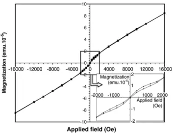
In order to verify this assumption, magnetic measurements were carried out at room temperature. The plot of magnetization Fig. 1. X-ray diffraction patterns of 300 nm thick films deposited with 5 W bias
power: (a) as-deposited films, (b) films annealed at 400 °C under primary vacuum.
Fig. 2. Atomic force micrograph of 100 nm thick film deposited with 5 W bias power.
versus field displays a weak hysteresis loop (Fig. 3). The coercivity of the film is close to 50 Oe. Magnetization is only expressed in electromagnetic unit for the whole sample. The specific magnetization is not given. In fact, due to the small size of the sample for SQUID measurements on the one hand, and the low thickness of the film on the other hand, the mass of the oxide deposited cannot be measured precisely. The hysteresis curve could be due to a secondary ferrimagnetic spinel phase so poorly crystallized it cannot be clearly revealed by X-ray diffraction. However, paramagnetic properties probably due to cubic Zn1− yFeyO are also superimposed because saturation
magnetization is very difficult to reach (Fig. 3). A loss of oxygen during the sputtering process is then responsible for the cubic zinc monoxide precipitation and zinc impoverishment of the remaining spinel phase. Assuming the monoxide is not perfectly pure zinc monoxide, the chemical reaction occurring in the sputtering chamber can be more precisely described by the following equation:
3
3−aZnxFe3−xO4Y 3a
3−aZn1−yFeyOþ Zn3x−3aþ3ay
3−a Fe9−3x−3ay3−a O4
þ2 3−aða ÞO2 ð1Þ
Two hours of annealing at 400 °C under primary vacuum, led to the crystallization of a spinel phase, in agreement with the previous interpretation of magnetic properties. Moreover, the annealed films are also made of cubic Zn1− yFeyO oxide, as for
as-deposited films, on the one hand, and hexagonal Zn1− zFezO
monoxide, on the other hand. From this result it can be inferred that iron is not dominant in starting Zn1− yFeyO because the heat
treatment under vacuum at 400 °C does not lead to metallic iron and magnetite, as observed for annealed wustite (y#1)[12,13]. On the other hand, hexagonal Zn1− zFezO monoxide could
result from the crystallographic transformation of part of the cubic Zn1− yFeyO phase. In fact, it has already been
demon-strated that cubic ZnO can be reversibly transformed into hexagonal ZnO (zincite), which is the thermodynamically stable allotropic variety at normal pressure and temperature[14–16].
Annealing the films in air at increasing temperatures lowers the monoxide level to the advantage of the spinel phase (Fig. 4). In fact, ferrous ion oxidation in
Zn3x−3aþ3ay
3−a Fe9−3x−3ay3−a O4
leads to cationic vacancy formation in the ferrite[17]allowing Zn1− yFeyO diffusion in the spinel phase. The chemical
equilibrium (1) is then displaced from right to left.
Cubic zinc oxide can only be stabilized under extreme conditions. At room temperature, a pressure higher than about 6 GPa is required to prepare this phase[16]. It is thus difficult to obtain, at least in the form of bulk material. Tanigaki et al.[18]
have however obtained both hexagonal and cubic zinc monoxide under mixtures of argon and oxygen, by the so-called flash evaporation technique. Rock-salt solid solutions of Zn1− xMgxO have been prepared by pulsed laser deposition
[19,20]. Thin films of rock-salt zinc monoxide with only 15 mol % of MgO were obtained when deposited on MgO substrates
[20]. Pure cubic zinc monoxide was only observed for nanometric powders (diameterb20 nm) obtained under very low partial pressures of oxygen. The stability at room temperature of such particles could be due to Laplace pressure resulting from their nanometric size. For similar reasons, cubic Zn1− yFeyO crystallites could be stabilized in as-deposited films
by the mechanical stress coming both from size effect and elaboration process. In fact, with the applied bias, positive ions are attracted by the sample holder. During its growth, the film is then bombarded with plasma species, as in a conventional sputtering process, but also with an argon ion flux which increases with the bias power. A strong in-plane compressive stress results from the bombardment phenomena. The partial substitution of zinc ions by iron ions must also contribute to the stabilization of the cubic allotropic variety of zinc monoxide.
The thin films prepared under 5 W bias power are semi-conductors as revealed by the decrease in resistivity with temperature. As-deposited 100 nm thick films have a resistivity of 0.7Ω cm at room temperature. These properties are similar to those observed for similar thin films for which the spinel phase was solely identified by X-ray diffraction[5].
Fig. 3. In-plane magnetic hysteresis curve of a 300 nm thick film deposited with 5 W bias power, on both sides of a 4.5 × 4.5 × 0.15 mm3glass substrate.
Fig. 4. X-ray diffraction patterns of 100 nm thick films oxidized in air at different temperatures.
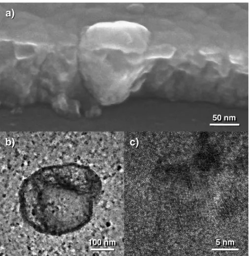
Varying the bias power changes the relative content of the crystalline phases. The films prepared without bias are ferrimagnetic and display the X-ray diffraction pattern of a spinel phase only (Fig. 5). However, careful microscopic observations show some “islands” bigger than the mean crystallite size (Fig. 6). As revealed by scanning electron microscopy, these larger grains are like wedges driven into the film and display higher zinc content than in the other parts of the
film. The Zn/Fe ratio was close to 1.4 in these regions. Because of this high zinc content, the large grains could contain Zn1 − yFeyO monoxide. The value of y can be estimated at around
0.4 from the local chemical measurements. The iron content could however be overestimated because the big grains do not run systematically across the film due to their shape (Fig. 6). In this way, a small part of the ferrite film located at the interface with the substrate is simultaneously analysed by the electron beam, leading to a decrease in global zinc content. The concentration of zinc atoms in the big monoxide grains obviously leads to a slight decrease in zinc content in the other parts of the film. The Zn/Fe ratio, close to 0.34 in these regions, is indeed lower than the average Zn/Fe ratio, which is 0.4 from electron microprobe measurements. Outside the monoxide grains, the film is very poorly crystallized. Only high-resolution microscopy was able to reveal some crystallites of about 10 nm in diameter (Fig. 6).
X-ray diffraction showed that sputtering with bias led progressively to the disappearance of spinel phase. Simulta-neously the number of previously described“islands” increased and cubic Zn1− yFeyO was revealed by X-ray diffraction. The
islands are then undoubtedly made of mixed zinc iron monoxide. That means the “a” parameter of Eq. (1) increased with substrate polarization. For bias powers equal or higher than Fig. 5. X-ray diffraction patterns of 100 nm thick films deposited at different bias
powers.
Fig. 6. Micrographs of films prepared without bias: (a) FEG-SEM image showing the ferrite film and zinc monoxide islands, (b) FEG-TEM image showing an island of zinc monoxide, (c) crystallite of ferrite observed by FEG-TEM.
5 W, only X-ray diffraction peaks of the monoxide phase can be observed.
The substrate bias enhances bombardment by positive ions, especially argon ions. The energy brought to the growing oxide layer by the incident species is partly transformed into heat, which increases film and substrate temperature, but also causes atom or ion ejection out of the oxide layer. The easiest chemical species to remove from the growing film are oxygen anions because they display a lower mass than metallic cations. Consequently, applying bias tends to contribute to the loss of oxygen according to reaction (1).
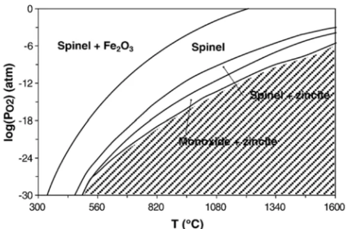
It is interesting to compare the effects of film polarization on phase evolution, when changing temperature and relative oxygen pressure in a Zn–Fe–O system. A phase diagram was calculated for bulk materials when Zn/(Fe + Zn) = 0.25 (Fig. 7). No surface effect was taken into account for the calculations. It can be observed in this phase diagram that reduction of bulk ferrite occurs at quite high temperatures or very low oxygen pressures. The substrate polarization is responsible for a slight increase in temperature on the one hand, and loss of oxygen on the other. The increase in bias power had thus an effect similar to raising the temperature and lowering the oxygen partial pressure. Using these analogies, the phase diagram is consistent with the reduction of oxide films as the bias power is increased. When sputtering the ferrite target, the oxygen partial pressure in the chamber was estimated to be at most 10− 12atm. At these partial pressures, temperatures close to 850 °C would be required to reduce the spinel ferrite. But the glass substrates used in this study would melt at this temperature. Even though the precise temperature of the substrates was not measured, it must be lower than the melting point of the glass used (# about 500 °C). Considering then that 500 °C is the maximum temperature for the substrate, the phase diagram shows that oxygen pressures as low as about 10−30atm would be required to start the spinel reduction. The global oxidation states of the films prepared under polarization could then be obtained for quite extreme conditions (high temperature or very low oxygen pressure) according to the phase diagram. These experimental conditions are very difficult to create to prepare bulk or powdered materials. Moreover, to get both spinel ferrite and
cubic zinc monoxide, a high mechanical pressure would be required. Consequently, comparing our experimental results with phase diagram calculations emphasizes the very specific surroundings in which oxide films can be prepared by sputtering with bias.
4. Conclusion
Composite thin films, made of cubic Zn1− yFeyO monoxide
islands inside a spinel ferrite matrix, were prepared by RF sputtering. The relative proportion of each phase depends on bias power applied. When no bias was applied the films solely displayed the diffraction pattern of a spinel phase even if islands of Zn1− yFeyO monoxide were observed by electron
microsco-py. When the bias power was increased, the spinel phase decreased progressively and formation of cubic Zn1− yFeyO
islands was enhanced. Thus, for bias powers higher than 5 W, monoxide phase was solely revealed by X-ray diffraction.
When annealed under primary vacuum at 400 °C, the cubic monoxide was partly transformed into hexagonal monoxide. If the annealing was carried out under air, the monoxide became progressively dissolved in the spinel phase. This phenomenon is possible because of preliminary spinel phase oxidation.
When the substrate was biased, the film was bombarded during its growth by different species, especially argon ions. These preparation conditions are similar to those of conven-tional ceramic processes i.e. very low oxygen partial pressure, high temperature and mechanical pressure. However, bias sputtering does not require an ultra-high vacuum setup and avoids excessive substrate heating and external mechanical stress to create these conditions, making the preparation of metastable oxides possible on ordinary glass substrates. Advantage should be taken of this method to prepare further original oxides and composite materials.
Acknowledgement
The authors thank Armand Gabriel from LTPCM in Grenoble for his help in thermodynamic calculations.
References
[1] Ph. Tailhades, B. Gillot, A. Rousset, J. Phys. IV (C1) (1997) 249. [2] E. Mugnier, I. Pasquet, A. Barnabé, L. Presmanes, C. Bonningue, Ph.
Tailhades, Thin Solid Films 493 (2005) 49.
[3] H. Windischmann, Crit. Rev. Solid State Mater. Sci. 17 (1992) 547. [4] T.J. Wink, W. Walrave, J.L.C. Daams, A.G. Dirks, M.A.J. Somers, K.J.A.
van den Aker, J. Appl. Phys. 74 (1993) 988.
[5] S. Capdeville, P. Alphonse, C. Bonningue, L. Presmanes, Ph. Tailhades, J. Appl. Phys. 96 (2004) 6142.
[6] S. Ben Amor, B. Rogier, G. Baud, M. Jacquet, M. Nardin, Mater. Sci. Eng. B57 (1998) 28.
[7] L. Bouet, Ph. Tailhades, A. Rousset, J. Magn. Magn. Mater. 153 (1996) 389.
[8] C. Despax, Ph. Tailhades, C. Baubet, C. Villette, A. Rousset, Thin Solid Films 293 (1997) 22.
[9] R. Cowburn, Mat. Today 6 (2003) 32.
[10] S. Pearton, C. Abernathy, M. Overberg, G. Thaler, D. Norton, N. Theodoropoulou, A. Hebard, Y. Park, F. Ren, J. Kim, L. Boatner, J. Appl. Phys 93 (2003) 1.
Fig. 7. Calculated phase diagram in the system Zn–Fe–O (with Zn/(Fe+Zn) = 0.25).
[11] P. Sharma, A. Gupta, F.J. Owens, A. Inoue, K.V. Rao, J. Magn. Magn. Mat 282 (2004) 115.
[12] G. Srinivasan, M.S. Seehra, J. Appl. Phys 55 (1984) 2327.
[13] J.M. Claude, M. Zanne, C. Gleitzer, J. Aubry, Mem. Sci. Rev. Metall. (France) 74 (1977) 229.
[14] C.H. Bates, W.B. White, R. Ray, Science 137 (1962) 993. [15] J.C. Jamieson, Phys. Earth Planet. Interiors 3 (1970) 201.
[16] F. Decremps, J. Zhang, R.C. Liebermann, Europhys. Lett 51 (2000) 268.
[17] G. Dupré, A. Rousset, P. Mollard, Mater. Res. Bull 11 (1976) 473. [18] T. Tanigaki, S. Kimura, N. Tamaura, C. Kaito, Jpn. J. Appl. Phys 41 (2002)
5529.
[19] E.R. Seguit, A.E. Holland, J. Am. Ceram. Soc 48 (1965) 409.
[20] M. Kunisu, I. Tanaka, T. Yamamoto, T. Suga, T. Mizoguchi, J. Phys. Condens. Matter 16 (2004) 3801.