HAL Id: hal-01591816
https://hal.inria.fr/hal-01591816
Submitted on 22 Sep 2017HAL is a multi-disciplinary open access archive for the deposit and dissemination of sci-entific research documents, whether they are pub-lished or not. The documents may come from teaching and research institutions in France or abroad, or from public or private research centers.
L’archive ouverte pluridisciplinaire HAL, est destinée au dépôt et à la diffusion de documents scientifiques de niveau recherche, publiés ou non, émanant des établissements d’enseignement et de recherche français ou étrangers, des laboratoires publics ou privés.
Distributed under a Creative Commons Attribution| 4.0 International License
Structuring and Composition Mechanisms to Address
Scalability Issues in Task Models
Célia Martinie, Philippe Palanque, Marco Winckler
To cite this version:
Célia Martinie, Philippe Palanque, Marco Winckler. Structuring and Composition Mechanisms to Address Scalability Issues in Task Models. 13th International Conference on Human-Computer In-teraction (INTERACT), Sep 2011, Lisbon, Portugal. pp.589-609, �10.1007/978-3-642-23765-2_40�. �hal-01591816�
Structuring and Composition Mechanisms to Address
Scalability Issues in Task Models
Célia Martinie, Philippe Palanque, and Marco Winckler
Institute of Research in Informatics of Toulouse (IRIT), University Paul Sabatier, France {martinie, palanque, winckler}@irit.fr
Abstract. Along tasks analysis and modeling history it has been demonstrated by
experience that task modeling activities become cumbersome when performed on large, real-life systems. However, one of the main goals of task models is to provide designers with a structured and complete description of the users tasks especially when these user tasks are numerous and/or complex. Several authors proposed to handle that problem by providing tools aiming at supporting both construction and understanding (usually via simulation) of models. One of the most popular examples is CTTE environment which is dedicated to the engineering of CTT task models. The paper shows how to extend notations for task description with two kinds of mechanisms: composition and refinement/abstraction. Refinement/abstraction mechanisms make it possible to decompose a task model into several models and to interconnect them. Composition mechanisms make it possible to define communication means between task models. The paper proposes a precise definition of these mechanisms, their integration into a notation for describing task models and demonstrates that altogether, these two structuring mechanisms support the effective exploitation of task models for large scale application. The use of the mechanisms is presented on a real-life case study from the space domain describing operators’ tasks to monitor a satellite and manage failures.
1 Introduction
In the field of Human-Computer Interaction (HCI), the user centered paradigm [22] has reached a popularity level where the question about it, is no longer whether it is valid or not but rather how it should be embedded in the development process of interactive applications. Many notations, processes and tools have been proposed for gathering information about the users either in formal (via formal requirements as in [17] or formal task models [27]) or informal ways (via brainstorming [7, 9] or prototyping [31]). One of the main advantages put forward by notations is that they make it possible to handle real-size applications and, if provided with a formal semantics, make it possible to reason about the models built with the notations1 and assess the presence or absence of properties.
While exploiting a notation for building a model of the real world, usually, two main activities are carried out in order to tackle the problem of size of the resulting model:
Abstraction: details from the real world will be omitted and abstracted away if they are not of interest for the use that will be made of the model. For instance, using a finite state automata (FSA) [14] the continuous evolution of the world (such as in a flow of liquid
1 In the rest of the paper we make the following distinction between a notation and a model: a
notation provides a mean for representing information from the real world. The resulting use of the notation is called model. If a notation is defined formally it is called a formalism.
while emptying a bottle) will be discretized in a set of states (for instance three different states: Full, Emptying and Empty) representing an abstraction of the infinite number of states of the real world.
Filtering: the notation plays the role of a filter capturing the information it is able to capture and letting through what cannot be captured. Taking again the example of a FSA, information about the time elapsed for emptying the bottle cannot be represented and thus will not appear in the model.
Of course, notations can be (and have been) extended in order to be able to represent more information than initially planned. FSA have been extended in [38] to handle data (such as for instance the size of the bottle) or even time [30]. However, the most widely used notations stay away from universality and embed strong abstraction and filtering. Examples of such notations are UML class diagram [29] or entity relationship diagrams [5] only capturing data-related information or basic Petri nets [23] or FSA [14] only capturing behavior-related information. Indeed, despite these mechanisms a notation capturing too much information would end up in oversized and unmanageable models. To represent a larger part of the world, several models have to be built using several notations. The complexity then lays in defining processes and tools making it possible to ensure conformance and consistency of the various models corresponding to different views of the same world.
In the field of HCI many notations have been proposed for capturing in models the various elements of socio-technical systems. In the last decades, several tasks notations have been developed as means to describe work carried out by users whilst interacting with a system [8]. Despite the fact that various specific task notations exist, they are mainly structured around two concepts: task decomposition (often represented as a hierarchy) and task flow (for showing the order in which tasks are executed) [16]. When adequately combined, these concepts can provide an exhaustive and complete representation of large quantity of information in a single model. However, as discussed by Paterno & Zini [28], when applied to real-life systems, tasks notations end up in very large, hard-to-manage models thus making task modeling a time-consuming and sometimes painful activity.
This paper introduces some generic structuring mechanisms to tasks notations for describing task models in order to overcome the problems identified above and to make it possible to represent users’ activities in large socio-technical systems. Section 2 discusses the structuring mechanisms offered by existing tasks notations. It also includes an abstract presentation of the proposed mechanisms. Section 3 introduces informally the real-life case study from the satellite ground segments domain focusing on controllers’ tasks to monitor a satellite and manage failures. It also presents an initial approach for modeling controllers’ tasks with CTT [26] and highlights the need for structuring mechanisms. Section 4 gives an overview of HAMSTERS (introduced in [1]) and details how the notation has been extended to integrate the new mechanisms. Section 5 details how the various elements of the notation are used to model the entire case study. Section 6 is dedicated to the analysis in terms of efficiency of the proposed mechanisms for structuring task models. Section 7 concludes the paper and presents research directions for future work.
2 Structuring Issues for Tasks Notations
Task models are useful when designing real-size systems as they aim at representing a large quantity of information related to user goals and to the activities to be carried out in order to reach these goals.
Notation-based structuring: Whilst some task notations such as UAN [13] and GOMS [4] are mainly textual, CTT [26, 24], MAD [33] or AMBOSS [1] provide graphical representations, which favor legibility and understanding of complex problems [6]. Every task notation proposes hierarchical task decomposition. This hierarchical representation of tasks is grounded in psychology [32] reflecting in the models the way people structure their activities. The decomposition of tasks in subtasks enables the creation of several levels in the tree hierarchy of tasks; this has been extensively used for supporting the mechanisms of abstraction and refinement in task models.
Not all notations used for describing activities are hierarchical. Indeed, notations used in the workflow domain (such as YAWL [36] or BPMN [36]) are graphs but hierarchical representations are more prominent in task model notations as this enforces abstraction/refinement mechanisms [36]. In hierarchical representations, the order of execution of tasks is given by the navigation through the hierarchy of tasks and the temporal operators between sibling tasks (i.e. tasks in the same level of the hierarchy). By combining hierarchy and temporal operators, it is possible to have different tasks models that exhibit equivalent behavior [10].
Another important issue for structuring task models refers to the relationship between tasks and goals. In the Task Knowledge Structure (TKS) [15] for instance, a specific substructure corresponds to each goal. CTT [26, 24], MAD [33], and GTA [35] provide a more flexible organization of tasks so that a goal can be reached in different ways. Van Welie, van der Veer and Eliëns [35] argue that the higher the tasks in the hierarchy the closer they are of organizational goals, whilst low-level tasks are more likely to represent individual goals. Even if the distinction between individual’s and organization’s goals is sometimes difficult to settle, it has in the end an impact on how models are structured.
Structuring mechanisms can sometimes be found in unexpected places. For example, CTT [26] includes the operator iterative tasks (symbol next to a task*) so that repetitive tasks are represented only once even though they may occur many times. That operator is mainly used for describing iterative behavioral aspect of the task but additionally makes it possible to significantly reduce the size of a task model. CTT offers another structuring mechanism via the notion of collaborative tasks modeled using the operator connecting
tasks (symbol ). In a nutshell, this notion embeds in models the fact that some tasks require the involvement of several persons (or roles) to be performed. The task of each person is modeled in a task model and the collaboration (i.e. order dependences between the tasks of the operators) is represented in another additional model. While necessary to represent collaborative activities, this notion and its related operator results in a role-based structuring of task models splitting a bigger model in several smaller models. CTTE is the unique tool currently available supporting collaborative tasks. However, only qualitative temporal relationships can be represented as no information (i.e. data flow) can be exchanged between the models.
An important issue that must be considered when structuring task models is its potential for reuse [3]. In fact, some tasks (such as login into systems for instance) remain structurally similar in different applications. This feature has been introduced in notations like CTT [26] so that some generic tasks can be used as building blocks that can be cut and pasted in models. However, a modification of one of these copies is not reflected to the other ones. Concerned by the reusability of tasks models, Gaffar et al. [12] have investigated structuring mechanisms around the notion of patterns to be used in task models. They propose a method and a tool to model generic tasks patterns as building blocks that can be instantiated and customized when modeling real-life socio-technical systems. One of the advantages of task patterns is the fact they provide more flexibility for reuse as they correspond to a generic problem.
Lastly, Sining et al. [34] introduce the notion of modular task models at a more generic level than the recursive tasks offered in CTT. Such modules would be structured in a task diagram describing in an exhaustive way their relationship. This concept is very similar to some one proposal in this paper. However, its implementation by means of task diagram adds unnecessary complexity (a new notation) and does not support the exchange of information between the modular models as proposed in the current paper.
Tool-based structuring: Some problems associated to the management of large and complex tasks models, can be overcome with the help of tool support. Currently, several of the tasks notations presented above are accompanied with an edition (and sometimes a simulation) environment. For instance, EUTERPE [35] supports the Groupware Task Analysis (GTA) notation, K-MADe supports the Méthode Analytique de Description (MAD) notation [33] and CTTE [25] supports CTT notation. These environments exploit the fact that task models are naturally represented as a hierarchy of sub-tasks, to implement abstraction/refinement mechanisms by supporting actions such as pruning/expanding sub-parts of the trees. More recently [28], CTTE tool has been enriched with visualization techniques (fisheye view and semantic zooming) to better support creation and management of CTT tasks models. Moreover, through collaborative tasks (previously described), CTTE is the only environment currently available supporting the decomposition of tasks in several communicating diagrams (even though the original goal was the representation of collaboration and not to support models structuring).
Abstraction/refinement and composition mechanisms: This section has illustrated the mechanisms currently available for structuring task models. However, when it comes to large systems these mechanisms and tools are insufficient (see CTT model in Fig. 2). We propose two new mechanisms to handle more efficiently this complexity. The first one is based on refinement/abstraction principle and makes it possible to decompose a task model in several models and to interconnect them. A large task model can thus be decomposed into several sub-models. These sub-models can then be reused (as a “copy”) in various places of the same model and even in other models. Each time one of these parts is modified, the modification is reflected in all the other “copies”. The Composition mechanism makes it possible to define communication mechanisms between task models. This task model structuring mechanisms is similar to procedures calls in programming languages and parameterization is possible via input and output parameters. In order to keep the same semantics as for the single model, communication protocols have also been introduced.
3 Case Study: Ground Segment Operations for PICARD satellite
In order to illustrate scalability problems of task models, in this section we present a real-life system belonging to a ground segment application that is currently used to monitor and to control the Picard satellite2. The task models presented in this section exploit standard
structuring mechanisms such as those currently available in the CTT notation (and presented above). These models will then be revised in section 4 to include the structuring mechanisms of abstraction/refinement and composition that we have designed to overcome the limitations that were faced due to the large number of tasks and activities.
3.1 Informa The case stu interactive s defined in t parts: the sp up of the gro the mission Fig. 1) wh maintaining and functio functions of here the ex decomposed much more real system 3.1.1 Groun The Operati hardware eq station segm satellite (spa of monitorin several para and status of nominal mo can be perfo al description udy belongs to systems of sa the European pace segment ound station s control syste hich belongs the spacecraf ning. Next p f the case stud xcerpt necess d and structur numerous tha in terms of co Fig. 1. nd Segment O ion Control Sy quipment dedi ment, 2) orga ace segment). ng the state ameters such a f the commun ode, so that th formed. If a s n of case stud o the space dom atellites. Fig. Standard EC (including the segment (anten m. Our focus to the missi ft in operation paragraphs de dy that have to ary to discu red. Indeed, ta an what is pre omplexity and The satellite Operations: th ystem consists icated to: 1) r anize and reco
In this room of the space as current vol nication link. T he mission (fo evere inciden dy
main and mor 1 presents a SS-E-70 [11] e spacecraft) nnas for comm s is the operat ion control s n and is thus h escribe the co o be represent ss the variou asks and oper esented here b d of operators’ application d he context s in a room co receive inform ord this infor m, controllers (
e segment pla ltage of the po The main goal or instance obs nt occurs, the
re precisely to schematic vi . Such space and the groun munication wi
tion control sy
system. This eavily related ontext, goals, ted in the task us models an rations of a m but this excer everyday act domain in a n ontaining seve mation from th rmation and 3 (usually calle atform part b ower generato l of operators servation of th satellite can o the command iew of a spac systems are m nd segment wh
ith the space s
ystem (bottom system is in to the spacec roles, tasks k models. We nd the way t mission contro rpt is represen ivities. nutshell eral computers he satellite vi 3) send comm d operators) a by examining ors, current sa is to keep the he sun by tak automatically d and control ce system as made of two which is made segment) and m-left icon in in charge of craft structure and system only provide they can be ol system are ntative of the s and various ia the ground mands to the are in charge periodically atellite mode, e satellite in a king pictures) y switch to a
mode called “survival mode” where all functions are disabled and the mission is stopped (i.e. data gathering is stopped and already collected data might be lost). In case of the occurrence of an adverse event, the team has to avoid that the satellite switches to this mode, except if it is to prevent a satellite loss. When a controller detects an adverse event (usually a failure) and understands the issue, he/she has to apply a procedure, selected from a list of referenced procedures, to recover from that failure. If the failure is more complicated to understand, he/she has to inform the entire team (one or more satellite engineer and experienced controllers can collaborate) to solve the issue and select the adequate procedure. If such procedure is not available they might need to design a new one that in turn has to be entered in the ground segment and sent to the space segment). The operator often collaborate with other controllers or with dedicated engineers such as, for instance, Radio Frequency engineers when special operations on the communication link are required.
3.1.2 Task analysis of a satellite controller’s activities
Controllers are in charge of two main activities: observing periodically (i.e. monitoring) the vital parameters of the satellite and performing maintenance operations when a failure occurs. Depending on the satellite between a couple of thousands and tens of thousands parameters have to be monitored. The more frequent and relevant monitoring activities include observing: satellite mode, Telemetry (measures coming from the satellite), Sun
array drivers statuses, error parameters for the platform, error parameters for the mission, power voltage (energy for the satellite), ground station communication status, and on board computer main parameters.
The number of procedures for maintenance operations goes beyond the hundred. Due to page limits, we only present a selection of three sub-routines concerning failure cases that are critical for the mission. However, these sub-routines allow us to exhibit all the problems that we faced and that were related to the structuring of task models. The sub-routines are:
Recovering from a power voltage issue: a wrong voltage parameter value is detected and the controller has to reset the satellite flight software.
Re-establishing the communication link: the ground operation control system may not be receiving Telemetry from the satellite. The first activity of the controller is also to reset the flight software in this case. The other activities are not presented. Investigating why an automatic switch to survival mode occurred: Most
satellites (including Picard) are not always all the time in ‘visibility’ of a ground station (only geostationary ones are). For such satellites the parameters are updated and the telecommands (TCs) sent when the satellite is visible for one of the ground station. Meanwhile, it evolves in an autonomous mode (self-triggering On Board Control Procedure (OBCP) if needed). During a non-visibility period if vital parameters’ values go beyond or below a given threshold, the satellite flight software (SW) switches itself to survival mode. In the next visibility period, controllers will have to understand what happened, find a solution and then send TCs to set the satellite back to its nominal mode.
Furthermore, after each failure detection and recovery sub-routine, the controller has to record the failure that happened in a dedicated application.
Lastly, the case study exhibits operators’ activities related to the management of the communication link between the Ground Segment and the Space Segment which also has to be monitored and possibly repaired.
3.2 Task mo Our first att models due [27] (and CT is not here t that the resu been decom view on the recovery. In model by th These two Telemetry is of multiple models. Mo …) is really it is not pos activity. Fig including su important to procedures already larg (described i nominal mo who then ad the “Failure flight softwa lack of struc of the tasks small differe failure. a) Top-view of b) Decomposit models (see fig
odel using CT tempt of mod to their size. TTe tool [25] to read the mo ulting model c mposed into se e two main n this model he symbol + co
tasks are det s highlighted t appearance o odifying inform y cumbersome ssible to expr g. 2c provides ubtasks Gener o note that the and related ta ge and comple n section 3.1 ode. For each dditionally rec e detection an are” which ap cturing mecha in the operati ences related t f controllers’ task tion of sub-task M gure below). Watch Telem TT deling operato We present h ) as this notat odel but to sh can be too lar veral models, operators’ tas we have use orresponding t tailed in Fig. to show where of the same t mation about e as these mod ress in CTT t s the decompo rator voltage
ese three task asks needed to ex. The mode
.2), and then type of failur cords the failu nd recovery” ppears twice a
anisms the co on of recordin to the fact tha
s, including Mon
Monitoring highli metry task
or’s tasks into here one of th tion is widely how first that
rge to be hand , all presented sks namely M d CTTe abstr to abstracting 2b and Fig. e it appears in task (which c it (name, dur difications hav the fact that t
osition for th issue, Comm ks only repres o control the el in Fig. 2c c 3 types of pr re, a special ta ure in a dedica sub-goal has and “Record f orresponding t ng a failure ar at they have to
nitoring and Failu
ighting the atomi
o sub-goals e he original m used in the H real-life tasks dled in an effi d in Fig. 2. Fig Monitoring an raction mecha g away further . 2c, respecti n both models could be an e ration, precon ve to be repea these two sub e tasks Failur unication loss ent a limited satellite, but contains 74 ta rocedures to s ask tree is pe ated applicatio several parts failure” which
tasks are dupl re also duplica o be customize
ure detection and
ic task Watch Te ended up with models using C HCI communit s can be mode cient way. Th g. 2a provides nd Failure d anism (repres r details about vely. The sub . This is a typ entire sub-tree dition, tempo ated manually b-trees represe re detection a s and Surviva subset of the despite that, asks, for 3 typ set the satellit rformed by th on. This is the in common h appears thre licated. Furthe ated, even thou ed according t
recovery
lemetry that also
h unreadable CTT notation ty. The point eled and then he tasks have s a high level detection and sented in the t these tasks). ubtask Watch pical example e) in various oral operators y. In addition, ent the same
and recovery al mode. It is e hundreds of the model is pes of failure te back to its he controller, e reason why (both “Reset ee times). By ermore, most ugh there are to the type of
c) Decomposit and Record fail
3.3 Issues r The modeli complex and One of th times (with procedures. various plac Additiona representatio associated to tasks in orde leads to th demonstrate but at opera is much hig order to han real-life com modeling. I Indeed, sma users’ activi
4 HAMST
In order to d used a tool Modeling to on HAMST the tool ha mechanisms 4.1 Short in HAMSTER designed to 3 it would hav but simulat Generat Reset flight Sion of task Failu
lure into the hiera
Fig. aised by the l ing of the ca d cumbersome he problems is hout specific To model thi ces of the task ally; currentl on of data flo o tasks, the de er to represen he multiplicat ed in Fig. 2. It ation time in t gher. This dem ndle such prob
mplex system ndeed, task m all scale system ities that are u
TERS and
demonstrate th l-supported n o Support Tas ERS, is that w s been devel s are generic a ntroduction to RS notation is remain comp ve been possib tion would have tor voltage issueRecord failu W
ure detection and
archy of subtask . 2. Models of o legibility and ase study usi
e activity. s that some ta temporal con is kind of beh models. ly available ow. To describ esigner must nt the expected tion of task is important t he Command monstrated th blems if they a ms. It is imp modeling is p ms usually do usually rather s
its Extensio
he use of the p notation calle sk Engineering we have the po loped by us). and thus could o HAMSTER inspired by e patible with C le to decompos e been impossib Co re Reset fligh Wa d recovery highli Generator voltag operators’ task d scalability o ing standard asks (in particnstraints) in havior it is re structuring m be complex c combine hiera d behavior. A s in the mo to note that we d and Control he fact that ta are to be used ortant to not precisely mea o not require th simple to desc
ons for Str
proposed struc ed HAMSTER g for Resilien ossibility to e . However, a d be integrated RS existing notati CTT (from th se the main mo ble ommunication loss Record ght SW atch Telemetryighting the reoccu
ge issue, Commun k using CTT n of the tasks m structuring m ular monitorin the same m quired to dup mechanisms onditions invo archies and op As a consequen odel, thus m e have only m Centre, the nu asks notations d for represent te that this a ant to be used he use of task cribe.
ructuring M
cturing mecha RS (Human-c nt Systems). T extend both th as stated in s d in many othe ions, especiall e point of vieodel into sub-m d failure
y task
urrence of tasks
nication loss and
otation. models of the c mechanisms r ng tasks) appe model or even plicate monito do not supp olving data an perators betw nce, the availa making them modeled 3 type umber of pos s have to be ing operators’ aspect is criti d for large sc models for un
Models
anisms for task centered Asse The rational fo e notation and section 2 we er notations an ly CTT [26] a ew of people odels within CT Survival mode Recor Reset flight SW Survival mode. case study resulted in a eared several n in several oring tasks in port accurate nd/or objects ween siblings’ able solution illegible as es of failures, sible failures extended3 in ’ activities in ical for task cale systems. understanding
k models, we essment and for the choice
d the tool (as e believe the
nd tools. and has been
building the
CTTe tool [25], rd failure
models) as m the tasks. H task execut HAMSTER provides a d connect task Objects form extensions constructs, i Abstract System ta User task task (e.g Perceptiv Interactiv refined in system p performe As in CT Fig. 3). Itera it can be in ENABLE o tasks do not F Additiona means of o represent bo might be m relationships (using the information task is conv discussion
models are hie However, HAM tions, data f RS models can dedicated API k models to s malism [20] that are requ including: task is a task ask is a task p k is a generic g. a physical ve task (e.g. pe ve task repres nto Input task rovides an ou ed in an atomic Task type Abstract Task System Task User Tasks Interactive Tasks TT, each partic ative property nterrupted or operator but o t require to be Fig. 3. Optiona ally, (as in C operators as oth informatio modified whe s between tas temporal ope flow between veyed to the n in the introd erarchical and MSTERS inclu flow across n be edited an I for observing system model and [21]. Th uired for stru that involves erformed only task describi activity), a C erception of a sents an inter when the use utput to the us c way. Table 1. cular task of th of tasks mean suspended b of an INTERR executed for al task Iterativ TT again) tem described in on and knowle en the task sks: the first erators as pre n tasks (as ill next task by m duction about d graphically r udes extensio task models nd simulated g editing and s [2] and [19 he notation p ucturing mod sub-tasks of d y by the syste ing a user act Cognitive tas alert).
raction betwee ers provide inp ser and InputO
Icons in HAMS Tasks types in H he model can ns that a task by another ta RRUPT or SU the goal to be ve task and of a mporal relatio [26]. In HA edge needed f is performed one describe esented above lustrated in Fi means of inp t tasks notat represented fe ons such as pr s, more deta in a dedicated simulation ev 9] based on th presented here dels. Table 1 different types m. tivity. It can b k (e.g. decisi en the User a put to the syst Output task w STERS task mod
HAMSTERS be either itera that can be ex ask. It should USPEND_RES e reached.
a task both iter
onship betwee AMSTERS, th for performin d. HAMSTER es how tasks e) and the se ig. 4 where th put and output tions it could eaturing opera re-conditions a ailed interact d environmen vents making i he Interactive eafter provide illustrates H s. be specialized ion making, and the System
tem, Output ta which is a mix del ative, optional xecuted 1 or s d not be a su SUME operat
rative and opti
en tasks is rep he notion of g a task. This RS offers tw are related to econd one re he PIN entere t ports). Acco d be argued ators between associated to tive tasks… nt which also it possible to Cooperative es additional HAMSERTS’ d as a Motor analysis), or em; it can be ask when the x of both but l or both (see several times; ubtask of an tor. Optional ional presented by f objects can s information wo types of o other tasks epresents the ed in the first ording to the that adding
information However, as perform they Fig. 4.2 Structur In order to a we have ide details how sub-routines have added (see Table 3) 4.2.1. Comp A sub-routin contexts wh The n The that c Spec icon. param requi repre to behavioral s such inform y must be exh 4. Input (right ring mechani address the sc entified 2 me these mechan s and the abst four types of ) and copy of t position mech ne is a group o hich might exh
name of the su icon of an “A can belong to cialized input . The graphic meters) or no ired paramet esentation of d Stru Sub-routine output valu Sub-routine value and n Sub-routine least one ou Sub routine value and a Table 2. G l models such ation has an im hibited in orde t-hand side of isms in HAM calability prob echanisms: co nisms are inte traction/refine f sub-routines tasks (or tasks hanism: sub-r of activities th hibit different ub-routine; Abstract” task different type and output p al symbol of ot (if they do ters to and data flow durin
ucturing mecha e with no input ue e with at least o no output value e with no input utput value e with at least o at least one outp
Graphical repre h as task mod mpact on the er to avoid und a task) and ou HAMSTERS MSTERS nota blems introduc omposition an egrated in HA ement by mea s (see Table 2) s sub-trees) (T routines hat a user perf
types of infor type (as the s es);
orts attached these special on’t). These p d/or from su ing task execu
anisms value and no one input value and at one input put value esentation of s
dels will degra availability o der-specified t utput (left-hand S ation ced in section nd abstraction AMSTERS: co ans of sub-mo ), parameters Table 4). forms several rmation flows sub-routine co both to the le lized ports can ports are mec ub-routines, ution. Related icon sub-routines in ade legibility f tasks and th tasks models. d side of a task n 3, (as stated n/refinement. omposition is odels. More p handling for times possibly . A sub-routin onsists of a gr eft and to the n be filled (if chanisms for thus provid n in HAMSTE n HAMSTERS for instance. he action they k) flow in in section 2) This section by means of precisely, we sub-routines y in different ne contains: roup of tasks e right of the f they handle representing ding explicit ERS
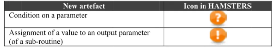
The sub-r the sub-rout to the value routine is re used by a ta parameter o inside the representatio parameters a Con Assi (of a 4.2.2. Abstr Table 4 prese another task correspond t thus replicat task type bu Sub T
5. Case st
Fig. 5 shows control of t Satellite mo (highlighted achieved co respectively Fig. 5. PIC routine is then tine. As stated e of the param epresented by ask for changif the sub-rout sub-routine. on makes it v and where in t N ndition on a para ignment of a va a sub-routine) Ta raction/refine ents the task i k in the model to the same su ted in all the s ut one “Copy”
Abstra
-model (copy) o
Table 4. Illustr
tudy model
s the main tas the Picard sa onitoring (high d by the blac oncurrently (| y in Fig. 6 a) an CARD satellite 1 n modeled in d above, the b meters (see T the symbol ing the behavi tine. The valu This assign very easy to id the model tho
New artefact ameter alue to an outpu ble 3. Input an ement mechan con used to in l. There can b ub-model. A m sub-models. T kind of icon i action/refineme of an existing O ation of sub-m
ling using t
sk model for atellite. This hlighted by th ck disc n°2). || temporal op nd Fig. 6 b). e monitoring a a dedicated m ehavior of the Table 3). In su . In the mai ior of the mod ue of the outpu nment is rep dentify in the se parameters ut parameter nd output para nism: sub-mo ndicate that th be several cop modification i Table 4 only re is available fo ent Output task models in HAMthe propose
the main ope main goal ca he black disc n These 2 sub perator) and and control ma model where t e sub-routine uch a case the
in task model del according ut parameter ( presented by sub-routine b s are modified Icon in ameters manag odels he task depicte
ies for a given in the sub-mo epresents the c or all the tasks
Icon in MSTERS (only
ed structur
erator goal wh an be subdiv n°1) and Failu b-routines are their detailedain task model
the root task i can be differe e precondition , the same sy to the value o (if any) has to y the symbo both the numb d.
n HAMSTERS
gement
ed by this icon n task and all del (including copy icon for t s types (see Ta n HAMSTERS for an output t
ing mechan
hich is the mo vided into 2 s ure detection a 2 sub-goals d structures a with HAMSTE 2 is the icon of ent according n in the sub-ymbol can be of the output o be assigned ol . Such ber of output S n is a copy of l these copies g its name) is the “Output” able 1). S task)nisms
onitoring and sub-routines: and recovery that can be are presented ERS5.1 Sub-routine with empty input and output parameters
In Fig. 6 a), the sub-routine corresponding to the sub-goal “Satellite monitoring” (part 1 of Fig. 5) is decomposed into 8 output tasks that are corresponding to the monitoring activities detailed in section 3.1.2. Fig. 6 b) details the “Failure Detection and Recovery” sub-routine (part 2 of Fig. 5) and is decomposed into a choice ([] temporal operator) of 3 sub-goals, which are depending on the type of failure discovered by the controller.
The first failure type corresponds to the power voltage issue, and is detected by the controller if he/she understands (cognitive task) that the power voltage parameter is wrong. This is done by observing or just having observed (while monitoring, Fig. 6 a)) this voltage parameter. His/her activities will then consist in resetting the satellite flight software and then recording this failure in the dedicated application. Second failure type (Fig. 6 b)) is a communication link loss and is detected by the controller when he/she understands that Telemetry from the satellite is not available anymore. His/her activities will then consist in resetting the transmission link. Third and fourth failure types (last task at the second level of Fig. 6 b)) detail the activities that are performed by the controller when he/she detects that the satellite has automatically switched to survival mode.
The second and third failure types may require the controller to perform a “Reset flight SW” procedure, which has been modeled (disc 4 on Fig. 6 b) as a sub-routine with empty input and output parameters. This sub-routine is very useful as it avoids duplicating an entire sub-task model. The sub-routine “Reset flight SW procedure” is detailed in Fig. 7 b). 5.2 Sub-routine with at least one input parameter and empty output parameter The “Record failure” sub-routine (disc 3 on Fig. 6 b detailed in Fig. 7 a) is performed by the controller each time a failure has been detected and aims at recording information in a dedicated desktop application about problems encountered in operations. An input value is required, because one or more of the group of tasks that are composing the sub-routine need information to be executed. As shown on Fig. 7 a), the record of a failure can slightly differ from one failure to another, and the input parameter of the sub-routine will also help in modeling the differences into sub-task trees (using the condition parameter introduced in
Table 3).
5.3 Sub-routine with empty input parameter and at least one output parameter In case of an automatic switch of the satellite to the survival mode (third failure type on Fig. 6 b), the controller will perform a procedure to find out the root cause of this issue. It is modeled by the “Find root cause of the switch” sub-routine, and this sub-routine provides an output object that will be used by the next sub-routine “Record failure (out)” to record the failure type that has been found.
5.4 Sub-routine with both input and output parameters
In case of a “Reset flight SW” sub-routine (disc 4 on Fig. 6 b detailed in Fig. 7 a), the controller has to prepare the RF communication link. The “Operate Com frequency” sub-routine requires an input and provides an output. It indicates that the information produced while preparing the RF is then used by the controller to reach his/her goal.
a) Fig. 6. Ta 1 sks of satellite b) Monitoring (a 2 a) and, failure 2
detection and recovery (b).
4 3 3 3 4 3
5.5. Conditi Fig. 7 a) sho failure sub-r the recordin types. In thi input value in the applic value of the In both cas alternative i precondition a) Fig. 7. a) R 3 ion on a para ows how the c routine. Indee ng of the fail is model, if th of the sub-rou cation; if the f sub-routine), es, failure tim is represented n on the failur Record failure ameter onditions on t d, in that mod ures but also he failure type utine), the con failure type is the controller me informatio d by the cho re type in=S b e sub-routine b
the input obje del, there is a o specific part e is a voltage ntroller is aske s a signal failu r is asked to e on and confir oice operator SIGNAL_FAI b)
b) and Reset fli
4
ect can be use common part ts which vary e issue (“VOL ed to enter the ure (“SIGNAL enter the failin
rmation are r and the fact LURE for ins
ight SW (softw d to customiz of the model y according to LTAGE_FAIL e power gener L_FAILURE” g transmission equired. In F that each ch tance. ware) sub-routi 5 ze the Record l dedicated to to the failure LURE” is the rator number ” is the input n equipment. Fig. 7 a) this hoice uses a ine 5
Fig. 8. O
5
5.6 Assignm Fig. 8 detail assignment storing of performed. I outcome of Besides, in e sub-routine the value “S and it is assi failed. 5.7 Sub-mo On Fig. 6 b) command to transmission status is alre the controlle between the Monitoring understand t is important model. If th modification when the CT
6. Analysi
6.1 Quantit Table 4 pre controller’s structuring between the other aspect any other no The first much highe number of n that promote on the numb The total about 20% u a bigger diff ment of a valu ls the “Operat of a value to history inform In Fig. 8 the a the sub-routin each sub-task always delive SUCCEEDEDigned the valu
odel of an exis ), in the secon o set the tran n) and look a eady described
er. The artifac e models and a task model d that this user’ t to note that he node is not n in one is ref TT model has
is of the Ca
tative analysi esents statisti activities, us mechanisms e two represen ts in the notati otation dedicat line of the ta er using the m nodes, arcs an es splitting a ber of models. l number of t using HAMST ference (66% ue to an outpu te Com Frequ an output pa mation about assignment ne which can, group, the ou ers an updated D” when the op ue “FAILED”sting task (co nd failure case nsmission to at the Telemet d in the Fig. 6 ct “Copy” of a avoiding dupli described in s activity is al this sub-mode t a leave task flected in all been presente
ase Study
s ics on the nu sing both CT proposed). It ntations lies fo ions themselv ted to task mo able (in italic mechanisms th nd operators is model into se asks required TERS notation reduction) as ut parameter uency” sub-ro arameter (excl t what happe out=SUCCE in turn, be us utput paramete d output param peration on thwhen the ope
opy) e “Communic ON (input ta try status. Th a) sub-routine an existing ta ication (copy Fig. 6 a)). Th lready referen el structuring k, then the en the copies. T ed. umber of mo TT and HAM t is importan or some aspect ves. However, odels would ex cs) highlights han without u s presented. T everal parts. T d to model the n together wit s far as both th r outine. It give lamation mark ened when t EDED record sed as conditio er is assigned meter. The “o he communica eration on the
cation loss”, th ask which cor his activity of e as it is part o ask is here use
of the “Watch his allows th nced in anothe can be applie ntire sub-tree
his issue has
odel elements MSTERS nota nt to note th ts in the struct adding those xhibit similar the fact that using them. T This is due to The sub-mode e controller’s th the structur he operators a es an example k icon) is use the sub-routin ds in the out p on in the main which guaran out” paramete ation frequenc communicatio he controller h rresponds to f observing th of the “Monito ed to maintain h at Telemetry e reader of t er part of the ta ed to any nod is managed a been raised in s needed to ations (togeth at part of th turing mechan mechanisms advantages. the number Then, for each
the sub-routi el extension ha
activities is d ring mechanis and the arcs ar
e on how the ed to support ne has been parameter the
n task model. ntees that the er is assigned cy succeeded, on frequency has to send a resetting the he Telemetry toring” job of n consistency y” task of the the model to task model. It de in the task as a copy i.e. n section 3.2 describe the her with the he difference nisms and for
to CTT or to of models is h model, the ine extension has no impact decreased by sms. There is re concerned.
This is due to the fact that operators are considered as part of the node in HAMSTERS and don’t need to be duplicated if the temporal operator between several tasks in a row is the same (as this is the case in CTT notation). The light grey lines in the lower part of the table correspond only to models appearing in the HAMSTERS modeling. They have no counterpart in CTT.
Notations Number of elements used for the case study according to the notations: CTT HAMSTERS
Number of models 4 6
Tasks for representing the main model 6 3
Operators for representing the main model 3 1
Arcs for representing the main model 11 3
Tasks for representing the “Monitoring” task model 9 9 Operators for representing the “Monitoring” task model 7 1 Arcs for representing the “Monitoring” task model 22 9 Tasks for representing “Failure detection and recovery” 74 20 Operators for representing “Failure detection and recovery” 52 7 Arcs for representing “Failure detection and recovery” 175 27 Tasks for “Operate communication frequency” 19 17 Operators for “Operate communication frequency” 11 7 Arcs for “Operate communication frequency” 40 23 Tasks for representing the “Record failure” task model - 15 Operators for representing the “Record failure” task model - 4 Arcs for representing the “Record failure” task model - 18 Tasks for representing the “Reset flight SW” task model - 14 Operators for representing the “Reset flight SW” task model - 5 Arcs for representing the “Reset flight SW” task model - 20
Total number of tasks 102 78 Total number of operators 73 25 Total number of arcs 248 100 Table 5. Quantitative comparison of the two modeling techniques 6.2 Qualitative analysis
Qualitative assessment is a more complex task which would require very detailed usability analysis of both the use of the structuring mechanisms and the idiosyncrasies of each notation. This is premature to the work presented here as it would require the distribution of HAMSTERS at a large scale (as this has been done for a long time with CTT) and then the setting up of an ethnographic study. However, even though such experiments were conducted we would face the same difficulties as those encountered in the late 80’s when the software engineering community was struggling to assess whether Object-Oriented programming was “better or not” with respect to “structured programming” [37]. Indeed, there are so many parameters involved such as training, maturity of tools, application domain, background of the developers … that a definite result is out of reach. Another related element is the user interface and interaction technique embedded in the tool supporting the notation. Indeed, even CTTE proposes the CTTVis extensions providing zooming and enhanced interaction techniques for task models edition. Such aspects have a he impact on the adoption and performance of user while building task models.
However, the current version of HAMSTERS tool is publicly available at http://www.irit.fr/ICS/hamsters/ and we plan to gather feedback from the future users.
7. Discussion and Conclusions
This paper has presented two new structuring mechanisms for notations dedicated to task modeling. We have shown how these mechanisms are different from the mechanisms currently available in the various existing notations. These mechanisms have been applied on a large case study from the space domain. We have used CTT notation as a reference point to support the reader who might be familiar with this notation and to compare quantitatively the size of the resulting models.
While this paper has focused on the mechanisms and the notation themselves this work belong to a long research program aiming at exploiting in a systematic way models in the design and validation of large (potentially safety critical) interactive systems. Indeed, these mechanisms would be extremely useful for addressing the issue of user errors in tasks models (in order, for instance, to identify scenarios exhibiting user errors) as in [24] or to support training of operators as in [18]. In the context of safety critical systems such elements are of primary importance as the resilience of the entire socio-technical system (including operators, procedures, training and computing system) has to be assessed prior to deployment.
References
1. Amboss,http://wwwcs.uni-paderborn.de/cs/ag-szwillus/lehre/ws05_06/PG/PGAMBOSS. 2. Barboni E., Ladry J-F., Navarre D., Palanque P. & Winckler M. 2010. Beyond modeling: an
integrated environment supporting co-execution of tasks and systems models. Proc. of the 2nd ACM SIGCHI symp. on Engineering interactive computing systems (EICS '10), 165-174. 3. Breedvelt, I., Paterno F., Sereriins, C.: Reusable structures in task models. In Harrison, M.D.,
Torres, J.C., eds.: DSVIS’97, Springer-verlag (1997) 251–265.
4. Card, S., Moran, T., Newell, A. The Psychology of Human-Computer Interaction, Lawrence Erlbaum, Hillsdale, 1983.
5. Chen, P., The Entity-Relationship Model - Toward a Unified View of Data, ACM Transactions on Database Systems, Vol. 1, No. 1, 1976, pp. 9-36.
6. Chattratichart, J., Kuljis, J. (2002) Exploring the effect of control-flow and traversal direction on VPL usability for novices. Journal of Visual Languages and Computing. v13. 471-500.
7. Dennis, A., & Valacich, J., Computer Brainstorms: More Heads are Better than One. Journal of Applied Psychology 78, 4 (1993), 531--537.
8. Diaper, D. & Stanton, N. A. (eds.) The Handbook of Task Analysis for Human-Computer Interaction. Lawrence Erlbaum Associates, 2004. 650 pages.
9. Diehl, M., & Stroebe, W. Productivity Loss in Brainstorming Groups: Towards a Solution of a Riddle, Journal of Personality and Social Psychology 53, 3 (1987), 497-- 509.
10. Dittmar, A. 2000. More precise descriptions of temporal relations within task models. Design, Specification, and Verification of Interactive Systems (DSV-IS'00). Springer-Verlag, 151-168. 11. European Cooperation for Space Standardization, Space Engineering, Ground Systems and
Operations, ECSS-E-70C, 31 July 2008.
12. Gaffar, A., Sinnig, D., Seffah, A., Forbrig, P. 2004. Modeling patterns for task models. In Proceedings of the 3rd annual conference on Task models and diagrams (TAMODIA '04). ACM, New York, NY, USA, 99-104.
13. Hartson, R.H. and Gray, P.D. Temporal aspects of tasks in the User Action Notation in Human Computer Interaction. Lawrence Erlbaum Associates, 1992. Vol. 7, pp. 1-45.
14. Hopcroft J. & Ullman J. Introduction To Automata Theory, Languages, And Computation, Addison-Wesley Longman Publishing Co., Inc., Boston, MA, 1990.
15. Johnson, H. & Johnson, P. (1991) Task Knowledge Structures: Psychological basis and integration into system design. Acta Psychologica, 78 pp 3-26.
16. Limbourg, Q., Pribeanu, C., Vanderdonckt, J. 2001. Towards Uniformed Task Models in a Model-Based Approach. 8th Workshop on Interactive Systems: Design, Specification, and Verification- (DSV-IS '01), Chris Johnson (Ed.). Springer-Verlag, London, UK, 164-182; 17. Mavin A. & Maiden N.A.M., (2003), 'Determining Socio-Technical Systems Requirements:
Experiences with Generating and Walking Through Scenarios', Proc. 11th Int. Conf. on Requirements Engineering, IEEE Computer Society Press, 213-222.
18. Martinie C., Palanque P., Navarre D., Winckler M. & Poupart E. Model-Based Training: An Approach Supporting Operability of Critical Interactive Systems: Application to Satellite Ground Segments, Proceedings of ACM SIGCHI EICS 2011, Pisa, ACM Press.
19. Navarre D., Palanque P., Bastide R., Paternó F. & Santoro C. A tool suite for integrating task and system models through scenarios. In 8th Eurographics workshop on Design, Specification and Verification of Interactive Systems, DSV-IS'2001; LNCS no. 2220. Springer Verlag 2001. 20. Navarre, D., Palanque, P., Ladry, J., and Barboni, E. 2009. ICOs: A model-based user interface
description technique dedicated to interactive systems addressing usability, reliability and scalability. ACM TOCHI 16,4 (Nov. 2009), pp. 1-56.
21. Navarre D., Palanque P. & Bastide R. (2003). A Tool-Supported Design Framework for Safety Critical Interactive Systems in Interacting with computers, Elsevier, Vol. 15/3, pp 309-328. 22. Norman, D. & Drapper, S. (Eds.). (1986) User Centred System Design. L. Erlbaum, U.S.,
ISBN-10: 0898597811
23. Petri, C. A. "Kommunikation Mit Automaten." Technical University Darmstadt (1962).
24. Palanque, P., Basnyat, S.: Task Patterns For Taking Into Account In An Efficient and Systematic Way Both Standard And Erroneous User Behaviours. IFIP 13.5 Working Conf. on Human Error, Safety and Systems Development (HESSD), Kluwer Academic Publisher (2004), pp. 109–130. 25. Paternò F. (2001). CTTE: An Environment for Analysis and Development of Task Models of
Cooperative Applications. ACM CHI 01 (Seattle, 2001) Extended Abstracts, ACM Press. 26. Paternò F. (2003) ConcurTaskTrees: An Engineered Notation for Task Model. The Handbook of
Task Analysis for Human-Computer Interaction. pp. 483-503. Lawrence Erlbaum Associates. 27. Paternò, F., Mancini, C. and Meniconi, S. ConcurTaskTrees: A Diagrammatic Notation for
Specifying Task Models. In: Proc. of Interact’97. Chapman & Hall (1997), 362-369.
28. Paternò, F., Zini, E. 2004. Applying information visualization techniques to visual representations of task models. Proc. of TAMODIA '04. ACM, New York, NY, USA, 105-111. 29. Rational Software Corporation. UML Notation Guide. 1.1 ed.1997.
30. Rajeev Alur. 1999. Timed Automata. In Proceedings of the 11th International Conference on Computer Aided Verification (CAV '99), Springer-Verlag, London, UK, 8-22.
31. Rettig M. "Prototyping for Tiny Fingers." Communication of the ACM 37, no. 4 (1994) 21-27 32. Sebillotte, S. Hierarchical planning as method for task analysis: the example of office task
analysis. Behaviour & Information Technology, 1362-3001, Vol.7, n°3, 1988, Pages 275-293. 33. Scapin, D. L. K-MADe. In: COST294-MAUSE 3rd International Workshop, Review, Report and
Refine Usability Evaluation Methods (R3 UEMs), Athens (March 5, 2007).
34. Sinnig, D., Wurdel, M., Forbrig, P., Chalin, P., Khendek, F.: Practical Extensions for Task Models. TAMODIA 2007. LNCS, vol. 4849, pp. 42–55. Springer, Heidelberg (2007)
35. van Welie, M., van der Veer, G. C., Eliëns, A. Euterpe - Tool support for analyzing cooperative environments. Ninth European Conf. on Cognitive Ergonomics ,pp. 25-30, August 24-26, 1998. 36. van Welie, M., van der Veer, G; C., Eliëns, A. An Ontology for Task World Models: In: 5th
International Eurographics Workshop on Design Specification and Verification of Interactive Systems DSV-IS98 ,pp. 57-70, 3-5 June 1998, Abingdon, UK.
37. Wieringa R. A survey of structured and object-oriented software specification methods and techniques. ACM Comput. Surv. 30, 4 (December 1998), 459-527.
38. Wood W.A. Transition network grammars for natural language analysis. Communications of the ACM 13, 10 (October 1970), 591-606