HAL Id: hal-01399027
https://hal.archives-ouvertes.fr/hal-01399027v2
Submitted on 19 Mar 2018HAL is a multi-disciplinary open access archive for the deposit and dissemination of sci-entific research documents, whether they are pub-lished or not. The documents may come from teaching and research institutions in France or abroad, or from public or private research centers.
L’archive ouverte pluridisciplinaire HAL, est destinée au dépôt et à la diffusion de documents scientifiques de niveau recherche, publiés ou non, émanant des établissements d’enseignement et de recherche français ou étrangers, des laboratoires publics ou privés.
Xavier Laval, Guanghan Song, Zhong-Yang Li, Pascal Bellemain, Maxime
Lefray, Nadine Martin, Alexis Lebranchu, Corinne Mailhes
To cite this version:
Xavier Laval, Guanghan Song, Zhong-Yang Li, Pascal Bellemain, Maxime Lefray, et al.. AStrion assets for the detection of a main bearing failure in an onshore wind turbine. CM 2016 - MFPT 2016 - 13th International Conference on Condition Monitoring and Machinery Failure Prevention Technologies, Oct 2016, Paris, France. �hal-01399027v2�
AStrion assets for the detection of a main bearing failure in an onshore wind turbine
Journal: CM 2016 and MFPT 2016
Manuscript ID Draft
Topic: CM applications
Date Submitted by the Author: n/a
Complete List of Authors: laval, xavier; GIPSA-Lab,
Martin, Nadine; GIPSA-Lab, Department Images Signal
Keywords: Monitoring, Failure diagnosis, wind turbine, AStrion
AStrion assets for the detection of a main bearing failure in an
onshore wind turbine
Xavier Laval, Guanghan Song, Zhong-Yang Li, Pascal Bellemain, Maxime Lefray, Nadine Martin, Alexis Lebranchu,
Univ. Grenoble Alpes, GIPSA-Lab, F-38000 Grenoble, France CNRS, GIPSA-Lab, F-38000 Grenoble, France
firstname.lastname@gipsa-lab.grenoble-inp.fr
Corinne Mailhes
IRIT/ENSEEIHT/TéSA, University of Toulouse, France corinne.mailhes@enseeiht.fr
Abstract
Monitoring the drive train of a wind turbine is still a challenge for reducing operation and maintenance costs and therefore decreasing cost of energy. In this paper, a standalone, data-driven and automatic tracking analyzer, entitled AStrion and already presented in this conference, is applied on vibration data acquired during one full year on a set of sensors located in the nacelle of two wind turbines in a wind farm in the Pyrénées (France). These experimentations were realized thanks to KAStrion project funded by KIC InnoEnergy program.
In the context of a particular case study, the main bearing failure of one of the two wind turbines, this paper will highlight three main assets of AStrion strategy. A first asset will be the application of the data validation module. According to the value of a nonstationary index, the data measured on the sensor located on the main bearing close to the failure have been discarded. This was justified afterwards by a dysfunction of the sensor. Then from the validated data acquired with a more remote sensor, a second asset will be the trends of global features computed by AStrion which proved a strong link with maintenance operations on the mechanical components such as the greasing. The third asset will be the reading of other AStrion features associated to one specific component. Indeed the trends of the features of the main bearing show evolutions throughout the year. A real time reading would have led to the conclusion of a severe evolution of the condition of this main bearing eight months before the failure and the stop of the machine. This study was carried out thanks to a narrow collaboration with the operator of the wind farm.
2
1. Introduction
The prediction of failures on industrial-scale system is a sure way to reduce significantly the operating costs. The duration of interventions is reduced and long delays without production because of a broken part are avoided. It is even more important for remote systems such as offshore wind turbines where on-site interventions are more complex.
The Condition Monitoring Systems (CMS) are widely used to realize these predictions and characterize the health of a system. CMSs have proven their efficiency on wind turbines (1,2). The current way to use a CMS is to empirically set thresholds on a set of features for alarm raising. However, the configuration is long and labor-demanding since it needs a dataset from the system in good health to determine these thresholds for each component. It is also system-dependent, and a change of the system forces a reconfiguration of the CMS. Hence such CMS are designated as system-driven ones.
On the contrary, AStrion is a data-driven system. Its different functionalities have already been presented at CM2015, as well as some application to the monitoring of wind turbines (3,4,5). AStrion automatically detects spectral peaks, gather harmonic families, calculates relevant fault features and tracks their evolution through the successive measures, thanks to the richness of the information extracted from the spectrum of the vibration signals. Furthermore, AStrion can also be adapted to the system studied by associating each mechanic components to a time-frequency trajectory, if detected. The spectrum investigation, the feature calculation, the kinematic association (optional) and the time-tracking of the features are automatic tasks. It makes AStrion perfectly suitable to be embedded in a wind turbine CMS since it is fully functional without any intervention of the user.
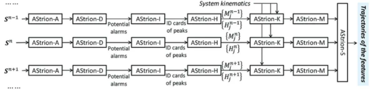
AStrion is composed with 7 modules. Its architecture is summarized in Figure 1 and abundantly described in (3).
Figure 1: The modular architecture of AStrion
Each signal is first submitted to an Angular resampling if needed (AStrion-A), a Data-validation (AStrion-D). Then the peaks are Identified (AStrion-I) and grouped into Harmonics series and sidebands (AStrion-H). These series are then associated to Kinematics elements (AStrion-K) if the system kinematics are known. The sidebands are deModulated to calculate the modulation functions (AStrion-M). Finally, a Survey of trends all the features obtained is performed in time over the signals (AStrion-S). The efficiency of some of these modules (A, D, K and S) will be evaluated in this paper.
3
AStrion has been installed on two wind turbines (WT8 and WT6) owned by VALOREM and exploited by one of its subsidiary, VALEMO.A major fault occurred on December 30th 2015 on the main bearing of the wind turbine WT8. AStrion had already been tested on the similar wind turbine WT6 from the same park (3), but had just proved its good reliability by not raising false alarms when the system was in good operational conditions. The data on both wind turbines were provided by VALEMO in order to test the effectiveness of AStrion to detect the fault. Thus the AStrion features have been used to characterize the fault, also providing other information such as the effect of maintenance operations or sensor problems.
However, the last 45 days of data are missing, and the sensor closest to the main bearing was faulty. This paper will show that, despite these hindrances, AStrion have been able to detect the faulty sensor and relevant proofs of a problem on this bearing, enough to raise an alarm for this specific bearing. Section 2 will present the wind turbines and the data selection which lead to the discarding of one sensor. Wide-band features will be presented in section 3, the standard one in order to prove they were not able to detect the fault. In this section, the AStrion-specific number of trajectories will show the effect of the maintenance on the state of the system. Finally, section 4 will focus on the main bearing trajectory and the trend of its features, proving the fault was predictable with AStrion. Section 5 will draw conclusions and some perspectives.
2. Arfons wind turbines and measures
2.1 Arfons wind turbines
The windfarm, located in the Pyrénées, is composed with eleven 2MW horizontal axis wind turbines in use since 2009. These are the most standard model. Its owner, VALEMO, is a partner of GIPSA-lab in the KAStrion European project, and had two of these turbines, noted WT6 and WT8, instrumented with data acquisition systems powered by ECSystems, another partner in this project. Thus 6 accelerometers had regularly recorded the vibrations on both turbines until mid-November 2015. These acquisitions have been performed in order to provide data to test the AStrion software.
4
Figure 2: (a) geographical location of wind turbines WT6 and WT8, and (b) quick overview of the mechanical system
Each wind turbine is composed of a rotor, a main bearing actually composed of two bearings, a planetary gearbox followed by a 2-stage parallel gearbox, and finally the generator. The two gearboxes contained numerous kinematics elements, making the final kinematic chain complex.
On December 30th, a major fault on the main bearing has provoked an interruption of the WT8. The damages are quite important. Currently, the wind turbine is still under investigation and reparation. The cost for the operator is thus quite consequent.
On the contrary, the other instrumented turbine WT6 of the same mechanical composition has not encountered any problem, and will serve as a reference for this study.
2.2 Instrumentation
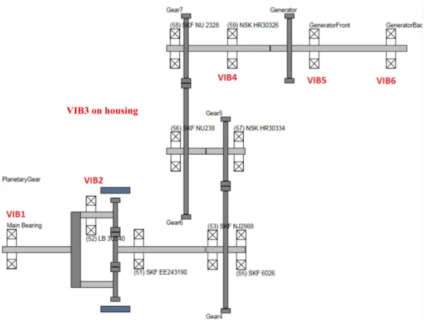
The 6 accelerometers are located on the system as shown on the kinematic drawing below:
Figure 3: name and location of the 6 accelerometers
The accelerometers are named from vib1 to vib6. Apart from vib3, which is on the housing of the two-stage parallel gearbox, they are located on bearings. The signals are
5
sampled at 25 kHz, and are recorded during 60s until January 19th, 40s after January 19th.
2.1 Data validation by AStrion-D
One year of signal acquisition, with measures every day, even every hour in January and February, provides a big dataset in which it is important to check the quality of the signal for a correct spectral analysis. Thus AStrion provides a relevant automatic data validation by means of the AStrion-D module based on 6 criteria: the time-domain saturation test, the Shannon sampling theorem test (6), the stationarity index (7), the fundamental periodicity rate, the dominant-power periodicity rate and the correlation support. Depending on selectable thresholds for each criterion, AStrion is able to automatically discard signals which, for example, are saturated, non-stationary, or have frequencies too close to the Shannon frequency, allowing a faster calculation for big datasets. It is also possible to discard signals by selecting an interval for the rotational speed of the reference shaft.
In the case of wind turbines, we determined that the most important criterion is the stationarity. Indeed, because of the variation of wind speed, a lot of signals are highly nonstationary, analysis is unreliable. However, few signals were found to be perfectly stationary (stationarity index equals to 0). According to the stationarity index definition (5,7)
, whose classification rule is given in Figure 4, we have placed the cursor of non-stationarity at 4% in the automatic data validation. Thus, we discarded every signal with a stationarity index over 4%.
_ _ 0%
0% _ _ 4% !
4% _ _ 16% !!
_ _ 16% !!!
Symbolic Classification
Stat index time freq Stationary
Stat index time freq Warning
Stat index time freq Serious warning
Stat index time freq Alarm
− =
< − ≤
< − ≤
− >
Figure 4: definition of the stationarity index
The only other parameter used for this selection was the rotational speed of the high-speed shaft connecting the gearbox to the generator. The signals are angularly resampled, by using this rotational speed as reference, through the AStrion-A module (3). However a speed range still had to be fixed. The maximum rotational speed of the turbine is around 1803 rpm, a higher rotational speed is prevented by the operator. It is the optimal rotational speed for power generation. A lot of signals are comprised between 1780 and this maximum speed, making it a natural interval for our study. However, in order to test the AStrion-A module, which helps reducing the non-stationarity caused by the variable rotational speed, we also worked with a 1600-1803 rpm interval. The results presented further are similar with both intervals. The 1600-1780 rpm points fit perfectly with the other points, proving the reliability of the AStrion angular resampling module.
6
At first, the Shannon test was also used for the automatic signals selection: every signal raising an alarm for this criterion was discarded. However, a lot of signals were presenting some high frequencies, close to the Shannon frequency. Removing these signals left not enough timestamps for the study to be relevant. Furthermore, the indicators used to detect the main bearing fault are low-frequency, and not likely to be disturbed by aliasing. Finally, the Shannon criterion has only been maintained for the number of trajectory feature.
Moreover, all measured signals passed the saturation test successfully.
2.2 Discarding of the main bearing sensor
The automatic data validation described above was performed on each sensor and revealed problems on the VIB1 sensor. This is the sensor located on the main bearing, and thus the one most likely to provide interesting information about the fault. Regrettably, the data validation phase as shown in Figure 5 revealed 2 problems:
• A high noise highlighted by the low value of the 3 remaining data validation criteria (fundamental periodicity rate, dominant-power periodicity rate and correlation support).
• No stationary signals (with the maximum 4% non-stationarity criterion) have been found after September 21st. This was explained by an unsticking of the sensor.
Thus VIB1 has been discarded.
Figure 5: data-validation of VIB1 (top) and VIB2 (bottom). The bad quality of VIB1 signals is clearly indicated by the abundance of red (alarm) on the last three
criteria.
Finally, the study will be conducted on signals from vib2 sensor, the second closest to the main bearing, on the wind turbine WT8. Only the signals with a rotational speed above 1780 rpm and a stationarity criterion below 4% will be used.
7
3. Global features evolution
3.1 Evolution of basic features
In order to prove the effectiveness of AStrion in this case, it is important to compare the results given by AStrion with those given by the standard wide-band features. These features are calculated on the whole spectrum of the angularly-resampled signal.
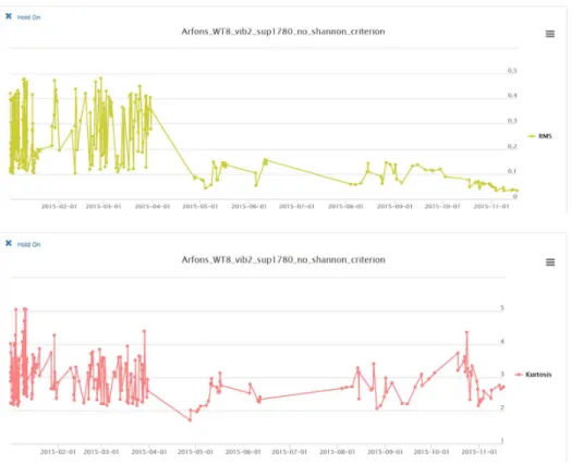
Figure 6: trend of RMS and kurtosis of the dataset signals.
As shown in Figure 6, these standard features do not detect any problems on the system. Their trends show no signs that a major breakdown of the main bearing is about to happen. Actually, the RMS value is even decreasing. Only the RMS and kurtosis are shown here, but other features such as crest factor and skewness have been calculated, and did not provide any more clues.
3.2 Trajectory number feature 3.2.1 About trajectories
The AStrion method consists in transforming the spectrum to peaks, then grouping these peaks into harmonic families and tracking these features over the dataset, thus creating a trajectory. Then the kinematic association, by the AStrion-K module, will look for trajectories associated to the different mechanical elements of the system, on the base of their theoretical frequencies or orders, usually provided by manufacturers. Unlike the standard approach, AStrion will automatically raise an alarm even if only one trajectory is having abnormal feature trend, indicating the faulty component to which this
8
trajectory is associated. Since the tracking result is updated for each signal, the number of trajectories for a signal depends of the number of signals already processed.
Numerous trajectories are detected on the dataset, but most will be tracked on only a few signals, not on a long duration. However, their number for each signal is relevant of the health status of the whole system, much more than only the number of peaks or the energy of the signal. Some mechanical components, such as gearboxes, generate a lot of frequency peaks even in a good state. On the contrary, a bearing in a good state generates very few. By grouping the detected peaks into harmonic families, and tracking these families over the timestamps, AStrion gives the same importance to each component. Thus, the number of trajectories is correlated to the number of components generating harmonic families, indicating the global health status. At a given timestamp, if a lot of trajectories are detected, it probably means that a lot of components are generating too much energy, and thus that the system needs maintenance.
3.2.2 Trend of the trajectory number
Following the trend of the number of trajectory on the whole dataset, we were able to link it to an important maintenance intervention, including greasing.
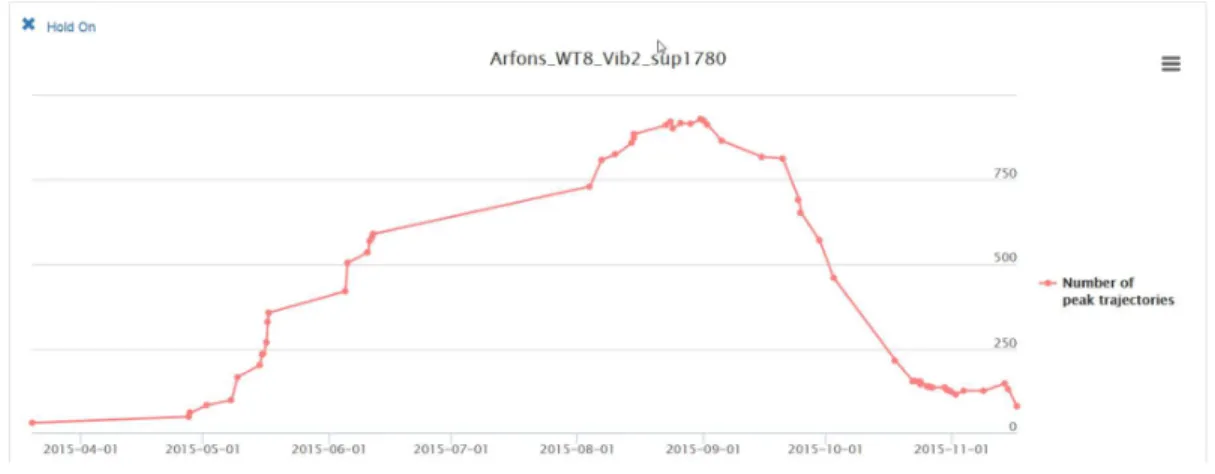
Figure 7: evolution of the trajectory number on WT8
Indeed, according to VALEMO, on September the 20th, a preventive maintenance has been performed on the different mechanical parts. This corresponds exactly to the start of the decrease visible in Figure 7: after this maintenance, the number of trajectories is decreasing rapidly from 800 to 150. This decrease is explainable by looking more closely on the detail of each mechanical component trajectory: nearly every trajectory detected for the bearings disappeared after this greasing. This is very clear on Figure 9. Actually, the only one which does not disappear is a trajectory associated to the faulty main bearing.
However for this study, since it is a global feature considering the whole spectrum, we had to take into account that a lot of trajectories were from high frequencies and not corresponding to kinematics elements. As previously mentioned, a lot of signals had frequencies too close to the Shannon limit, activating the Shannon criterion. Removing these signals prevents the bias of having too much high frequency trajectories, focusing
9
more the number of trajectory feature on the low frequencies trajectories, more relevant to characterize the mechanical parts health status.
This feature still needs to be improved, especially to focus on only the mechanical trajectories, and to be less dependent of the number of signals.
4. Time-frequency trajectory of the main bearing harmonic family
4.1 About the bearing trajectories
As previously said, a lot of trajectories are detected on each signal. However, focusing on the trajectories associated to a kinematic element reveals a lot of information on this element.
There are four main types of characteristic fault frequencies for a bearing:
• The fundamental train frequency • The ball spin frequency
• The ball passing frequency on the outer racer (BPFO) • The ball passing frequency on the inner racer (BPFI)
If AStrion detects a harmonic family trajectory which fundamental is close to one of these frequencies, it associates this trajectory to the kinematic element. Contrary to a classical way of monitoring, this association is done after the analysis and the peak detection. In the WT8 case, thirteen of these bearing frequencies have been associated to a trajectory.
Since this study is performed in the angular domain, after the angular resampling, all the frequency values are actually in orders. The value of each frequency associated to each mechanical part has been calculated during the PhD of Marcin FIRLA (8). As previously said, the main bearing is actually composed of two bearings. However, AStrion have detected trajectories on only one. It means the other one was probably undamaged before the breaking. Only this one had flaking and galling.
4.2 Trend of the fundamental frequency feature
Focusing on the BPFI of the faulty bearing, AStrion is able to precisely track its fundamental frequency. In order, its theoretical value is 0.316046. It is calculated (8) with,
BPFI =୬୰∗୰ଶ ቄ1 +ୢ୮ୢ୰cosሺ∅ሻቅ, (1) nr being the number of rolling element, fr the shaft speed expressed in Hz, dr the diameter of the rolling elements, dp the pitch diameter, and ∅ the angle of the load from the radial plane. The variations of the fundamental frequency of the faulty bearing BPFI harmonic family from the 1st of January to November the 16th are shown in Figure 8.
10
Figure 8: trend of the main bearing BPFI frequency In this figure, 2 facts are interesting to note:
• This harmonic family has been detected at nearly every timestamp.
• From August, the frequency value is slowly decreasing (-0.2% at mid-November).
The decreasing of the BPFI fundamental frequency is a sign of galling, an advanced state of wearing: the bearing is more and more resisting the rotation. However, it is a hard sign to track, the drop is not very important. When transforming the spectrum into peaks, AStrion applies 5 different spectral analysis methods, with different windows and estimator for each, and then merges the results. This approach makes the spectral analysis efficient to detect slight variations of the fundamental frequency.
4.3 Trend of the energy feature
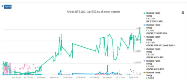
Another AStrion feature for each trajectory is the energy of the harmonic family. It is an obvious feature to examine. Figure 9 shows the energy associated to the BPFI harmonic family of the faulty bearing in brown, as well as the energy of every other harmonic family associated to the other bearings.
11
Figure 9: trend of the energy feature of every harmonic family associated to a bearing. The faulty bearing is in green.
A huge increase of energy is clearly visible from April. The harmonic family of the faulty bearing BPFI dominates every other family from there, with a trend to increase.
Furthermore, this figure clearly shows that this harmonic family is the only one which is almost constantly detected by AStrion. The other detected harmonic families disappear, especially after the maintenance of October. This is to be correlated to what was said in Section 3.2.2. Furthermore, AStrion has not detected any trajectory associated to the main bearing BPFI on the reference wind turbine, WT6. This alone is already a strong sign that something is wrong with the WT8 main bearing. Calculations on signals from early 2014 shows that this trajectory is already the most often detected, though not as much often.
5. Conclusions and prospective
Since AStrion is a data-driven CMS, it does not need information about the nature of signal. It analyses the whole spectrum, extract from it all important fault features, and tracks their trends over all the timestamps. As demonstrated, it is efficient for different aspects of condition monitoring. The data-validation module is able to warn the user when a sensor is not working correctly, or when the sampling frequency is too low. The tracking of the different trajectories provides information about both the global-health status, reacting to maintenance operation, and the health of the different parts through the kinematic association.
The tracking of the main bearing trajectory over the last year before its breaking allows relevant hypothesis about what happened. We can speculate that there were 3 steps in the bearing degradation:
• Before April, the BPFI harmonic family was already constantly detected. Knowing that it is the only bearing with a harmonic family trajectory constantly detected, we can assume there was already a defect on its inner ring, a flaking for example.
12
• From April to August, the huge increase of the energy of the BPFI harmonic family probably indicates that the defect has amplified, but was not yet threatening to destroy the bearing.
• After August, the decrease of the fundamental frequency indicates the initiation of galling, which is a very grave defect, eventually leading to the bearing blocking and brutal destruction.
The final diagnosis is still to be done, but pictures we are not permitted to show have been provided by the owner of the wind turbine, VALEMO. On the 2 bearings composing the main bearing, it is indeed the one which BPFI trajectory AStrion detected and tracked that has broken. The rollers have gone out of their housing, and the bearing is completely out-of-order. On these pictures, flaking and holes are visible on the faulty bearing inner ring and rollers. The outer ring is in a much better state. It is to highlight that the study in this article was conducted before any information and pictures was given, apart the fact that the main bearing was broken. AStrion have been able to predict automatically that the problem was on the inner ring. However, the Ball Spin Frequency should have been detected too, considering the state of the rollers. The problem may come from the low value of this frequency. A solution could be to perform a second acquisition, longer with a lower sampling frequency.
Though still in development, AStrion has passed this test on the detection of bearing flaking and galling. The richness of information extracted from the signal and the following of the different features trends allowed this prediction. In the future, an AStrion-embedded CMS on a wind turbine should prevent such a major fault to happen. This case study will prove very useful in the future automatization of the diagnosis, to provide not only alarms, but also information on which part is failing, and hypothesis about the kind of problem. However, other kind of faults will need to be analyzed with AStrion, on gears or gearboxes for example.
13
1.B. Lu, Y. Li, X. Wu, and Z. Yang, ’A review of recent advances in wind turbine condition monitoring and fault diagnosis’, Power Electronics and Machines in Wind Applications,
2.P. F. G. Márquez, A. M. Tobias, M. J. P. Pérez, and M. Papaelias, ’Condition monitoring of wind turbines: Techniques and methods’, Renewable Energy, vol. 46, pp. 169 - 178, 2012.
3.Zhong-Yang Li, Timothée Gerber, Marcin Firla, Pascal Bellemain, Nadine Martin, et al.. ‘AStrion strategy: from acquisition to diagnosis. Application to wind turbine monitoring’. Twelve International Conference on Condition Monitoring and Machinery Failure Prevention Technologies. CM 2015, Jun 2015, Oxford, United Kingdom.
4.Nadine Martin. ‘KAStrion project: a new concept for the condition monitoring of wind turbines’. Twelve International Conference on Condition Monitoring and Machinery Failure Prevention Technologies CM2015, Jun 2015, Oxford UK, United Kingdom.
5.Guanghan Song, Zhong-Yang Li, Pascal Bellemain, Nadine Martin, Corinne Mailhes, ‘AStrion data validation of non-stationary wind turbine signals Topic: Condition monitoring (CM) methods and technologies’. Twelve International Conference on Condition Monitoring and Machinery Failure Prevention Technologies. CM 2015, Jun 2015, Oxford, United Kingdom.
6.Matthieu Sanquer, ‘Detection and characterisation of transient signals. Applications to the monitoring of electrical load curves’. Joint supervision with Florent Chatelain, MC INPG. and M. El-guedri, EDF, Chatou EDF Grant. Univ. Grenoble thesis. Defended March, 15, 2013
7.Nadine Martin, Corinne Mailhes, ‘A non-stationary index resulting from time and frequency domains’. Sixth International Conference on Condition Monitoring and Machinery Failure Prevention Technologies. CM 2009 and MFPT 2009. Dublin, Ireland, 23-25 June 2009
8.Marcin Firla, ‘Current and vibration analysis for a preventive condition monitoring. A specific approach for offshore wind farms’. European Project KAStrion. UGA Univ. Grenoble Alpes thesis. Defended January 21, 2016.