HAL Id: hal-00298578
https://hal.archives-ouvertes.fr/hal-00298578
Submitted on 3 Apr 2007
HAL is a multi-disciplinary open access
archive for the deposit and dissemination of
sci-entific research documents, whether they are
pub-lished or not. The documents may come from
teaching and research institutions in France or
abroad, or from public or private research centers.
L’archive ouverte pluridisciplinaire HAL, est
destinée au dépôt et à la diffusion de documents
scientifiques de niveau recherche, publiés ou non,
émanant des établissements d’enseignement et de
recherche français ou étrangers, des laboratoires
publics ou privés.
Development of an automatic multiple launcher for
expendable probes
G. Zappalü, F. Reseghetti, G. M. R. Manzella
To cite this version:
G. Zappalü, F. Reseghetti, G. M. R. Manzella. Development of an automatic multiple launcher
for expendable probes. Ocean Science, European Geosciences Union, 2007, 3 (2), pp.173-178.
�hal-00298578�
www.ocean-sci.net/3/173/2007/
© Author(s) 2007. This work is licensed under a Creative Commons License.
Ocean Science
Development of an automatic multiple launcher for expendable
probes
G. Zappal`a1, F. Reseghetti2, and G. M. R. Manzella2
1CNR-IAMC, Section of Messina, Messina, Italy 2ENEA-CRAM, S. Teresa di Lerici (SP), Italy
Received: 10 May 2006 – Published in Ocean Sci. Discuss.: 25 July 2006 Revised: 31 October 2006 – Accepted: 14 March 2007 – Published: 3 April 2007
Abstract. A main goal of a Ship Of Opportunity Programme
(SOOP) is the provision of temperature profiles in near real time. The use of commercial ships and expandable probes allows the reduction of costs, in comparison with research ship cruises. A major cost effectiveness is achieved using an automated multiple launcher, requiring minimum person-nel effort. A multiple launcher, developed in the framework of the Mediterranean Forecasting System – Toward Environ-mental Prediction Project (MFSTEP), allows for a sequen-tial collection of eight temperature profiles, using a software-programmable sampling strategy. The data acquisition sys-tem can be remotely controlled in every functionality, and data can be transmitted by GSM-GPRS or satellite telephone systems.
1 Introduction
A Ship Of Opportunity Programme (SOOP) was established in the Mediterranean in September 1999, on behalf of the EC-funded project Mediterranean Forecasting System – Pi-lot Project (MFS-PP, Pinardi et al., 2003). XBT profiles were collected along six sections crossing the Western and the Eastern basins from North to South, and one crossing the whole Mediterranean Sea from East to West. These sections were designed to specify the variability of the main circula-tion features in each of the sub-basins (the Algero-Provenc¸al, the Tyrrhenian, the South Adriatic, the Ionian and the Levan-tine) ( ¨Ozsoy et al., 1991, 1993; POEM Group, 1992; Hecht and Gertman, 2001; Fusco et al., 2003; Millot and Taupier-Letage, 2005; Zodiatis et al., 2005).
The initial purpose of the study was the continuous and regular sampling of the Mediterranean upper thermal struc-ture using XBT measurements. This also included the
de-Correspondence to: G. Zappal`a
velopment of quality criteria for data collection and manage-ment as well as the improvemanage-ment of near real time data ex-change capabilities. The technology was the same as that used in the international SOOP programme (Smith et al., 1999): Sippican launcher LM3A, read out card MK12 (or MK21) and XBT probes for data acquisition, and ARGOS for data transmission. The temperature profiles were sub-sampled by the ARGOS software, and coded for transmis-sion on the GTS (Global Telecommunications System) in the BATHY format (AODC, 1999, 2001; Cook and Sy, 2001; Manzella et al., 2003).
In recent years, the data collection strategy (including sampling design, technologies for collection and transmis-sion of data) was tested and implemented. The same was done with the near-real time (NRT) data management, in-cluding NRT quality control (QC) and data access. Data transmission was achieved with a regular GSM phone, used as a modem for Internet connection. The EDF (Sippican Ex-change Data File) full resolution files were compressed and sent attached to an e-mail. This simple improvement was made possible by the GSM coverage available in the Mediter-ranean coastal region. Transmitting the full resolution pro-files required a change in the QC procedures, and software based on Medar-Medatlas protocols (MedAtlas Group, 1994) was developed. It contains all the steps of the delayed mode QC: gross range check, position control, elimination of spikes, resampling at 1-m interval, Gaussian smoothing, general malfunction control, comparison with climatology. Two visual checks were added at the beginning and at the end of the QC procedure in order to detect the end of a given profile and to monitor the overall consistency of the profiles (Manzella et al., 2003).
The operational performances of the data acquisi-tion/transmission/delivery to users were fully demonstrated during two main projects supported by the European Commission: Mediterranean Forecasting System – Pilot Project and Mediterranean Forecasting System – Toward
174 G. Zappal`a et al.: An automatic multiple launcher for expendable probes Environmental Prediction. The assessments carried out at
the end of the projects included an analysis of the scientific, technological and economic aspects of a Ship Of Opportunity Programme in the Mediterranean Sea. The scientific aspects of the programme are illustrated in a paper by Manzella et al. (2006).
An ideal operational observing system is based on four goals:
– Provide repetitive measurements along sections from
coast to coast;
– The sections must cross significant dynamical features
of the circulation;
– The sampling distance should resolve the mesoscale as
well as possible;
– The technologies for data collection must be robust and
simple, to be used on ships of opportunity, also by ship personnel.
The cost of the observations performed through ships of op-portunity with the use of XBT is small compared to the costs of research cruises but it is not sustainable by a research com-munity. Some technological implementations could make the use of voluntary ships (VOS) still more cost effective. This can be achieved by the selection of tracks, the devel-opment of multiparametric observation systems and of auto-mated data collection systems.
Automated systems were developed in Japan and the United States. The TSKA AL-12 multiple launcher, for instance, can be loaded with 12 XBT probes that can be launched following some established criteria. The launcher, linked to a personal computer and a Sippican data acquisi-tion card, consists of revolving tubes that are put in launch position by an electric engine. The probe’s security pin is re-moved by a second engine and a third one opens (and closes) the doors of the tubes to allow the XBT to fall in the sea. It was used at the end of Pilot Project with the launching system managed by a software allowing the selection of the probe type and the launch at defined sampling intervals. The con-clusion was that the machine is robust enough for all weather conditions and reliable but hard to handle, heavy and requir-ing a continuous surveillance. Furthermore, the presence of three electric engines made the device hardly serviceable by ship personnel, in case of malfunction (U.S. Department of Transport, 2003). Based on this experience, a second solu-tion consisting of a series of tubes along one or two lines was selected, since it was minimising the number of moving elements.
This paper presents some background information on the technology used in the Mediterranean-SOOP, and the char-acteristics of the developed multiple launcher prototype, that was used during two cruises.
2 Acquisition system in MFS-TEP
The standard acquisition system used in MFS-TEP project consists of a hand-held probe launcher (LM3A), a read-out MK21 (or MK12) card installed in a PC with an ISA slot (or a MK21 unit USB linked), and an interface box between launcher and read-out card. The used probes were either Sip-pican XBT (T4, T5, T6, T7, DB, and FD) or XCTD (D-1).
Data collection is controlled by the MK21, and the buffered I/O stores the data until it can be read by the host computer. MK21 uses DSP technology (Digital Signal Pro-cessing) for on-board processing and has a flash memory for in-system programming capability, allowing the users to add newly developed probe capability and firmware upgrades. The software performs system diagnostics and pre-launch tests, indicating that the probe is ready to be launched. It receives data during the descent, and displays and stores the data, which is translated to ASCII text format. The MK21 Windows Software has auto GPS (NMEA 0183) input ca-pability, selectable IGOSS or original fall rate coefficients, and post-processing options. The sampling rate depends on the dropped probe: 10 Hz for all XBT types and 25 Hz for XCTD.
The current linkage between the probe and the record-ing system is established when the probe canister is placed within the launcher and the launcher breech door is closed.
Once the security pin is removed and the probe moves down, the wire decoils from the probe as well as from the spool within the probe canister. The system uses the water as grounding: when the electrode within the probe’s nose makes contact with the sea water, the circuit is closed and the volt-age is telemetered to the data processing equipment on board ship.
The system grounding is connected to the seawater grounding from a lug on the outside of the box to some metal part of the hull of the ship, and should measure less than 100 Ohm from the connection box to the seawater. The val-ues measured by the Sippican XBT controller are converted into voltage, then into resistance and, finally, into temper-ature (expressed in degrees Celsius) using the relation dis-covered by Steinhart and Hart (1968), and the coefficients obtained by Georgi et al. (1980). When the probe reaches the depth selected by software (or the wire breaks off), the profile is terminated, and the acquisition system is ready for another launch.
3 The multiple launcher
The new system is an integrated set of mechanical and elec-tronic hardware and software giving the user the maximum of flexibility. The system is composed of two parallel series of launch tubes, built in AISI 316 steel, in which the probes are fitted with their casing. Upper caps, on which the electri-cal connections of the probes are installed, close the launch
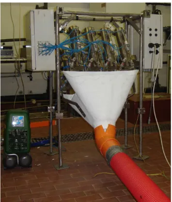
Fig. 1. The multiple launcher with the electro-valves box (left) and
the electronics box (right), on the floor the air compressor (left) and the red pipe connected to the funnel to drive probes outboard.
tubes. The lower part of the tubes is closed by doors: opening the lower doors, the probes are released and fall into the sea-water. Two pneumatic cylinders control each door: a small one keeps it closed, a bigger one moves it. This is the only “engine” contained in the multiple launcher. In the actual design, the system assembles eight launch tubes with their pneumatic actuators on a frame; two watertight boxes host the computerised control system and the electro-pneumatic valves feeding the cylinders (Fig. 1). All operations are con-trolled by an industrial grade computer, based on IEEE 696 compliant boards, interfaced with GPS-receiver, data acqui-sition and communication devices. Both analog and digital interfaces are available to collect data coming from the most various devices (passive and active expendable probes, me-teorological sensors, ...).
A balanced source circuit (Fig. 2) was designed to inter-face standard passive temperature probes with 12 or 16 bit analog to digital converters. Two identical currents are in-jected in both of the wires originating from the probe and the potentials VAand VBare measured; the circuit is closed
by the sea water. The switch Sw1 (a relay contact) enables testing the continuity of the probe circuit before the launch. A high precision fixed resistor (simulating a probe) can be automatically measured before starting launches to obtain a check of the instrument calibration.
B Rsea A Rwire1 Rwire2 Rthermistor I1 I2 Rballast Rballast Vsea Vw1 Vw2 Vth B A x 1 x 1 x 2 to ADC Sw1
Fig. 2. The schematics of the probe interface board.
To avoid any perturbation to the measurements, a multi-ple stage amplifier was used to adapt the signal coming from the probe to the need of the ADC; the circuit was built us-ing high quality precision instrumentation amplifier ICs. The first stage uses unity gain configuration, having high input and low output impedance; the second stage is a differen-tial amplifier with gain = 2. The last stage is a low output impedance low-pass filter with gain = 1 and ft = 40 Hz. The mean of 16 (VB-VA)measurements is calculated ten times
a second (this acquisition rate can be changed by operator request), obtaining the voltage across the NTC probe ther-mistor, whose resistance is deduced from Ohm’s law, or, bet-ter, using the regression coefficients obtained after calibra-tion of the circuit against a set of standard high precision resistors (Fig. 3). The XBT voltage readings converted into resistance are then transformed into temperatures using the standard formula by Steinhart and Hart (1968) by means of Georgi et al. (1980) coefficients.
The output is a time-series of temperature values, whose depth can be calculated using the IGOSS or the Sippican original fall rate coefficients. Remote communications are performed using a GPRS modem with an embedded TCP-IP stack; a serial port is available to connect other communica-tion devices (e.g. satellite modems).
4 The software
A software capable of managing 96 launch events was devel-oped. Launch options are:
– Drop position to be northern (southern) than a
pre-defined latitude and eastern (western) than a pre-pre-defined longitude;
– Drop position to be far from a previous station; – Drop time at GPS- or PC-time.
The collected data is stored locally and can be transmitted as e-mails. A local control program (written in Microsoft Compiled Basic v. 7.1 with routines in Assembly Language, running in Datalight DOS environment, and executed on the
176 G. Zappal`a et al.: An automatic multiple launcher for expendable probes Ohm read y = 0,9933x - 26,801 R2 = 1 0 2000 4000 6000 8000 10000 12000 14000 16000 18000 0 2000 4000 6000 8000 10000 12000 14000 16000 18000 Ohm set
Fig. 3. Regression between high precision standard resistor and the
corresponding values measured by the multiple launcher circuit.
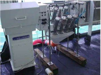
Fig. 4. The multiple launcher on the deck of the Italian
Hydro-graphic Institute ship Magnaghi.
launcher control computer), manages all the launcher func-tions, i.e. real time and position acquisition, comparison against set points-times, launch, data acquisition and trans-mission, ancillary functions.
Every hour, a “sequence manager” starts a macro-command sequence that can be different for each time and is remotely re-programmable; new releases of the software and the sequences can be uploaded at the station, without suspending its normal activity. The macro-commands allow to manage the data acquisition and transmission, the mission programming, the station hardware and the measuring instru-ments.
The entire system can be connected to a computer (local laptop or remote desktop), in order to use a remote con-trol program, written in Microsoft Visual Basic, running in Windows environment. This program enables to set up all the launcher functionality, to transfer files to and from the launcher, and, if needed, to take control of all the launcher operations, including the time-position acquisition and com-parison. -310 -260 -210 -160 -110 -60 -10 13 15 17 19 21 23 25 27 °C
Fig. 5. Profiles collected with the multiple launcher with the ENEA
boat moving.
5 In situ tests
The first in situ tests of the multiple launcher were performed in March 2006 using the Italian Hydrographic Institute vessel Magnaghi and in June 2006 with the ENEA boat S.Teresa, in the Ligurian Sea – North Western Mediterranean. Figure 4 shows how the multiple launcher can be fitted in a ship, assur-ing safety to operators and undisturbed operations. Durassur-ing these tests, data was recorded from the multiple launcher to verify the efficiency of the whole system (hardware and soft-ware), and, for comparison, XBT probes were launched with a standard Sippican system (hand launcher LM 3A, MK21 read-out card).
Figure 5 shows profiles obtained by the multiple launcher. Temperature values collected at few depths demonstrate the high quality of the multiple launcher profiles.
6 Discussion and conclusions
The multiple launcher development aimed at improving the cost-effectiveness of an operational observation system. The possibility to have a light, simple and robust system allows
easy use by ship personnel. This instrument requires a simple power connection and very limited space (about 1×0.5 m). As usual, the best solution is to have a place on a ship side, possibly leeward. The automatic multiple launcher was tested in laboratory and during two short cruises. The profiles recorded by the multiple launcher system show temperature values compatible with other measurements. Compared to the existing hand launcher system, the improvement is ev-ident. The multiple launcher allows automatic launches of a certain number of probes (eight XBTs, in the actual ar-rangement) without human intervention. With respect to the TSKA AL-12 multiple launcher, which was tested in the past, the newly developed device has a minor amount of electric or mechanic parts, increasing the reliability of the entire system. Significant improvement is achieved by the lighter weight (about 30 kg instead of about 120 kg), also due to the ab-sence of electric motors with related protections from sea wa-ter. A further advantage is the possibility to manage the sys-tem remotely, although this functionality was not yet used. The multiple launcher (just like the Sippican manual one) requires the manual removal of the security pin from each canister, whereas in the TSKA AL-12 the pin is removed by a motor, but this functionality causes weight and cost.
Another advantage of the multiple launcher is that it is an “all-in-one” system. The transmission system, GPS, data logger and computer are all housed inside the apparatus, therefore there is no need for the external PC required by Sippican and TSKA; and the acquisition time can be easily set by the operator.
The multiple launcher has not yet been tested for drop-ping other multi-parametric probes, such as XCTD. Improve-ments for this should be possible by simply adding a new interface board.
A final remark is devoted to cost reduction that can be achieved by using a multiple launcher. One of the require-ments in operational oceanography is the collection of data allowing the spatial resolution of mesoscale phenomena, which are of the order of 15–20 miles in the Mediterranean Sea. Since ships are moving faster than 20 knots, the XBTs must be dropped every 20–30 min. Data collection along a section 400–500 miles long with a single Sippican launcher requires the engagement of two-three technicians, having a cost of about 25 USD per hour. The total cost for personnel amounts to 1000–2000 USD for each travel. The cost of a multiple launcher is about 15 000 USD, that can be recovered in 10–20 travels by engaging only one person.
Acknowledgements. The activity was funded as part of the
MF-STEP project, 5th EU FP. The authors acknowledge the support provided by N. Pinardi and G. Coppini. The work performed by technicians during these years has provided the necessary information for the design. The authors wish to thank A. Baldi and F. Conte from ENEA, for their invaluable technical support during the preparation and development of the multiple launcher and in data collection during the tests. The authors acknowledge the contribution of the referees to improve the quality of the paper.
Edited by: N. Pinardi
References
AODC: Guide to MK12 – XBT System (Including Launch-ing, returns and faults), Australian Oceanographic Data Centre (AODC), METOC Services, 1–63, 1999.
AODC: Expendable Bathythermographs (XBT) delayed mode, Quality control manual, Australian Oceanographic Data Centre (AODC), Data Management Group, Technical Manual 1/2001, 1–24, 2001.
Cook, S. and Sy, A.: Best guide and principles manual for the Ships Of Opportunity Program (SOOP) and EXpendable Bathythermo-graph (XBT) operations, Prepared for the IOC-WMO-3rd Ses-sion of the JCOMM Ship of Opportunity Implementation Panel (SOOPIP-III), March 28–31, 2000, La Jolla, California, USA, 1–26, 2001.
Fusco, G., Manzella, G. M. R., Cruzado, A., Gacic, M., Gas-parini, G. P., Kovacevic, V., Millot, C., Tziavos, C., Velasquez, Z., Walne, A., Zervakis, V., and Zodiatis, G.: Variability of mesoscale features in the Mediterranean Sea from XBT data analysis, Ann. Geophys., 21, 21–32, 2003,
http://www.ann-geophys.net/21/21/2003/.
Georgi, D. T., Dean, J. P., and Chase, J. A.: Temperature calibration of expendable bathy-thermographs, Ocean Engineering, 7, 491– 499, 1980.
Hecht, A. and Gertman, I.: Physical features of the eastern Mediter-ranean resulting from the integration of POEM data with Russian Mediterranean cruises, Deep-Sea Research I, 48, 1847–1876, 2001.
Manzella, G. M. R., Scoccimarro, E., Pinardi, N., and Tonani, M.: Improved near real time data management procedures for the Mediterranean ocean Forecasting System – Voluntary Observing Ship program, Ann. Geophys., 21, 21–32, 2003,
http://www.ann-geophys.net/21/21/2003/.
Manzella, G. M. R., Reseghetti, F., Coppini, G., et al.: The improve-ments of the Ships Of Opportunity Program in MFSTEP, Ocean Sci. Discuss., 3, 1717–1746, 2006,
http://www.ocean-sci-discuss.net/3/1717/2006/.
MedAtlas Group: Specification for Mediterranean banking and re-gional quality controls, IFREMER, Direction Scientific, Sismer-Brest, SISMER/IS/94-014, pp 29, 1994.
Millot, C. and Taupier-Letage, I.: Additional evidence of LIW en-trainment across the Algerian Basin by mesoscale eddies and not by permanent westward-flowing vein, Progress in Oceanography, 66(2–4), 231–250, 2005.
¨
Ozsoy, E., Hecht, A., ¨Unl¨uata, ¨U., Brenner, S., O˘guz, T., Bishop, J., Latif, M. A., and Rosentroub, Z.: A review of the Levantine Basin circulation and its variability during 1985–88, Dyn. At-mos. Oceans, 15, 421–456, 1991.
¨
Ozsoy, E., Hecht, A., ¨Unl¨uata, ¨U., Brenner, S., Sur, H. ˙I, Bishop, J., Latif, M. A., Rozentraub, Z. and O˘guz, T.: A synthesis of the Levantine Basin circulation and hydrography, 1985–1990, Deep-Sea Res., 40, 1075–1119, 1993.
Pinardi, N., Allen, I., Demirov, E., DeMey, P., Korres, G., Las-caratos, A., LeTraon, P. Y. Maillard, C., Manzella, G., and Tzi-avos, C.: The Mediterranean ocean Forecasting System: first phase of implementation (1998–2001), Ann. Geophys., 21, 3–
178 G. Zappal`a et al.: An automatic multiple launcher for expendable probes 20, 2003,
http://www.ann-geophys.net/21/3/2003/.
POEM Group: General Circulation of the Eastern Mediterranean Sea, Earth Science Review, 32, 285–309, 1992.
Smith, N. R., Harrison, D. E., Bailey, R., Delcroix, T., Hanawa, K., Keely, B., Meyers, G., Molinari, B., and Roemmich, D.: The role of XBT sampling in the ocean thermal network, OCEANOBS St Raphael 18–22 October, 1999.
Steinhart, J. S. and Hart, S. R.: Calibration curves for thermistors, Deep-Sea Res., 15, 497–503, 1968.
U.S. Department of Transport: New Generation Polar Re-search Vessel – Newsletter, Issue 2, http://www.usap.gov/ vesselScienceAndOperations/documents/prvnews sept03.pdf, September, 2003.
Zodiatis, G., Drakopoulos, P., Brenner, S., and Groom, S.: Variabil-ity of the Cyprus warm core Eddy during the CYCLOPS project, Deep Sea Res., II 52, 2897–2910, 2005.