HAL Id: hal-00432355
https://hal.archives-ouvertes.fr/hal-00432355
Submitted on 16 Nov 2009
HAL is a multi-disciplinary open access archive for the deposit and dissemination of sci-entific research documents, whether they are pub-lished or not. The documents may come from teaching and research institutions in France or abroad, or from public or private research centers.
L’archive ouverte pluridisciplinaire HAL, est destinée au dépôt et à la diffusion de documents scientifiques de niveau recherche, publiés ou non, émanant des établissements d’enseignement et de recherche français ou étrangers, des laboratoires publics ou privés.
periodicaly segmented waveguide
Pierre Aschieri, Valérie Doya, Antonio Picozzi
To cite this version:
Pierre Aschieri, Valérie Doya, Antonio Picozzi. Complex behavior of ray in gaussian index profile periodicaly segmented waveguide. J. Opt. A: Pure Appl. Opt., 2006, pp.386-390. �hal-00432355�
periodicaly segmented waveguide
Pierre Aschi´eri, Val´erie Doya and Antonio Picozzi Laboratoire de Physique de la Mati`ere Condens´ee
University of Nice-Sophia Antipolis Parc Valrose, Nice, France
Abstract. In this article, we present a numerical analysis concerning ray propagation in a multimode periodic segmented waveguide with a gaussian index segment profile. We show that this simple waveguide configuration exhibits a complex ray dynamics that can be regular or chaotic depending on the initial conditions.
PACS numbers: 05.45.Pq Numerical simulations of chaotic systems, 42.82.-m Integrated optics
1. Introduction
Periodic Segmented Waveguide (PSW) is a waveguide formed by an array of high index segments embedded in a low index substrate. It has been shown that this kind of waveguides exhibits several interesting properties. They have been used in linear applications to make tapers or mode filters [1, 2, 3], by exploiting the fact that the mode size and the propagation constant can be adjusted by varying the duty-cycle (defined as the ratio of the high index segment over the period ΛP SW). Elsewhere, they
have been used to achieve efficient nonlinear guided wave interaction using the Quasi Phase Matching (QPM) or Balanced Phase Matching (BPM) schemes [4, 5, 6] that take advantage of a periodic reversal of the nonlinear coefficient associated with such waveguides. More recently they have been shown to exhibit interesting properties that can be useful for optical power limiting or managing applications [7, 8].
We have applied a ray analysis in the simple and ideal 2D case of a PSW characterized by a transverse gaussian index profile. The choice of the gaussian shaped index segment is motivated by the fact that such kind of profiles are naturally encountered in standard waveguide fabrication such as the usual proton exchange technic in LiN bO3 [9]. It will be shown in this paper that the ray dynamics induced
by a transverse gaussian index profile is a much more complex ray dynamics than that encountered with the usually considered parabolic index profile [10, 12, 13]. In particular, we show that the gaussian index profile is responsible for the emergence of a genuine chaotic behavior of the ray dynamics. Such a complex behavior is actually comparable to what has already been studied in a periodically perturbed waveguide [14, 15].
After a description of the system used, preliminary numerical results will then be discussed and finally, conclusions and perspectives will be drawn.
2. Numerical model
A schematic representation of a transverse gaussian index PSW is sketched in figure 1. A step index profile is assumed along the propagation direction z as it has been done in previous works [10]. Note that a smoother profile will not changed qualitatively our results. A ray path in a 2D medium can be described by the following equation in cartesian coordinates [16]: d2 x dz2 = 1 2β2 dn2 (x) dx (1)
where, x and z are the transversal and longitudinal coordinates respectively, n(x) is the transverse index profile, β = n (x0) cos θ0 is the invariant of the ray path, x0 being the
initial position of the ray and θ0 being the incident angle of the ray respect to z axis. The
ray path can be calculated by analyzing high and low index segments separately. We consider here dielectric waveguides characterized by a low index contrast δn ≈ 0.02 1,
which allows us to neglect the reflections of rays at each interfaces. In the low index segment, n (x) = ns is constant, so that equation (1) is reduces to :
d2
x
dz2 = 0 (2)
whose solution corresponds to (2) a straight ray. The high index segment is characterized by the following transverse gaussian index profile :
n (x) = ns+ δne−
x2
ω2 (3)
In the limit of usual classical assumption δn 1 equation (1) then reads: d2 x dz2 = − 2nsδn β2 ω2 xe − x2 ω2 (4)
A numerical technic is required to integrate the ray path equation (4). The numerical integration is performed using the classical Runge Kutta (RK) technic [17]. Starting from initial conditions
x (0) = x0 dx
dz (0) = θ0,
(5)
One can compute the ray path step by step by solving alternatively equation (2) and equation (4) by using the law refraction of each interface.
It is important to note that the gaussian shape profile makes equation (4) nonlinear respect to variable x, whereas for a parabolic index profile, equation (4) reduces to a linear equation [18]. For a parabolic PSW, the presence of a linear term in the RHS of equation (4) makes the system analogous to a parametric system [19] exhibiting parametric resonances. These resonances are responsible for a ray divergence whatever initials conditions, a feature that has already been pointed out in a previous work [10] and extended to gaussian beams [12, 13] where a similar instability may occur. For a gaussian index PSW, the situation is different because the nonlinear term in the RHS of equation (4) saturates the parametric instability and makes happen nonlinear resonance. Same phenomenon will arise for other index profiles as soon as the RHS of equation (4) is nonlinear respect to x such as, for example, exponential, erfc or sech profiles. The corresponding nonlinear resonance makes the ray dynamics much more complex as will be shown in the next section. It has to be mentioned that such a dynamics of ray propagation is comparable to the dynamics of an undamped nonlinear pendulum forced by a periodic motion of the suspension point. In complete analogy with a parametrically forced pendulum, we will show that a gaussian index PSW exhibits nonlinear resonances, frequency locking, as well as a chaotic behavior [11].
3. Results
The numerical technic outlined in the previous section has been used to compute a ray path in a gaussian profile PSW. It is worth noting that for a step [1, 20, 21] or a parabolic [10, 12] index transverse profile, some relevant waveguide properties
such as the propagation constant and the mode size, can be easily obtained from an equivalent uniform waveguide model. The refractive index difference δneq of the
equivalent waveguide is defined as an average of high and low index segments:
δneq= δn×duty-cycle (6)
where, δn is the refractive index difference between the substrate and the guiding segments and the duty-cycle is defined as duty-cycle = d/Λ where d is the segment length and Λ is the period (figure 1). The ray path of a PSW with a gaussian index profile and its equivalent uniform waveguide model are plotted on figure 2 [22]. One can note that the ray paths coincide so that the focusing period Zp is almost identical
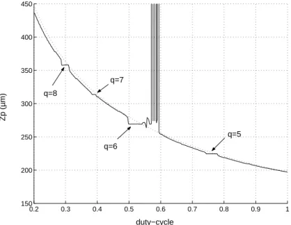
for both waveguide. However, it can be shown that for some waveguide configurations the equivalent uniform waveguide approximation is no longer accurate. In figure 3, the focusing period Zp is plotted as a function of the duty-cycle for a gaussian index PSW
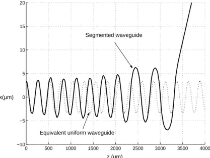
and its equivalent uniform waveguide. The waveguide parameters are the same used as in figure 2, except that the period is now Λ = 45µm. While the two curves are very close for most of the duty-cycle values, one can note some well pronounced differences for some particular values of duty-cycle. For duty-cycle taken between 0.55 and 0.6 the focussing period for the PSW tends to infinite, a feature which signals a divergence of the ray path. This is illustrated in figure 4, which represents the ray path for duty-cycle = 0.55. After a short propagation distance, the focusing period Zp of the PSW deviate from the
period corresponding to the uniform waveguide one, the amplitude oscillations of the ray increases and around z = 3500µm, the ray escapes from the guiding region. One can also note in figure 3 that the PSW curve exhibits some steps in which the focussing period Zp remains constant for a given range of duty-cycle values. This important feature could
not be describe with the equivalent uniform waveguide model. We are in the presence of a parametric nonlinear resonance which manifests itself through a period-locking (or frenquency-locking) between two characteristic periods of the system: the segmentation period Λ and the focussing period Zp. Period-locking occurs when the two periods (or
the two frequencies) are commensurate with each other, i. e., when their ratio is a rational number q = Zp/Λ. (One period is locked into being a rational number time q of
the other period). Period-locking can be clearly identified for a ratio equal to 8, 7, 6 and 5 on figure 3. Other nonlinear resonances may also be identified for non integer values of q, but they are not clearly visible in figure 3. From a practical point of view interesting features may occurs in terms of waveguide dispersion associated with those nonlinear resonances. The average waveguide index has changed but Zp and then the optical path
length remain constant and, as a consequence, the transit time do not vary with the waveguide parameters. It means that is a waveguide dispersion free configuration.
With the help of the Poincar´e’s section, one can get an deeper insight of the ray dynamics. Poincar´e sections are a convenient and widely used representation of a periodically perturbed nonlinear system. It consists of a projection of the trajectory (x, θ, z) onto the phase plane (x, θ) at positions z = nΛ, n = 1, 2, 3, ... [22]. Figures 5, 6 and 7 represent Poincar´e sections for duty-cycle = 0.3, duty-cycle = 0.55 and
duty-cycle = 0.75 respectively for an ensemble of various initial conditions regularly distributed in phase space. Poincar´e sections reveal that the dynamics is characterized by the coexistence of a regular or a chaotic behavior, depending on initial condition. A stable trajectory is constructed on a 3D torus known as a KAM (Kolmogorov-Arnold-Moser) torus which is characterized by a close curve circle on the Poincar´e section. The corresponding value of q is irrational so that the ray densely covers the closed curve during its propagation. If an initial condition is taken on one of those closed curves circle, the ray path remains confined on the waveguide. On the other hand, initial conditions taken in the stochastic region surrounding the peripheral KAM torus generate an unstable trajectory that leads to a quick divergence of the ray because there is no more total internal reflection on a high index segment or the low index segment is too long and the ray cannot be recoupled into an high index segment. A set of stable islands results from a break up of one of the KAM tori in the case of a rational q value and it is the trace of a single trajectory. This corresponds to a subharmonic resonance, in which the period of the ray path Zp is larger that the waveguide period Λ. For example,
if the initial condition is taken in A (on figure 5), the next position at z = Λ is in the other island (A1), the next one is in A2 at z = 2Λ. So that the ray path returns to the first island at z = 8Λ. After a while the points closely cover the set of 8 islands. Then, a rational q value generate 2q fixed points which corresponds to q pairs of hyperbolic and q elliptic points. Elliptic points refer to nonlinear resonances in which the period of the trajectory is synchronized with the period of the segmentation. For example, for duty-cycle = 0.3 (figure 5), duty-cycle = 0.55 (figure 6) and duty-cycle= 0.75 (figure 7), 8, 6 and 5 elliptic points are visible on the Poincar´e sections, which respectively correspond to q = 8, q = 6 and q = 5. The corresponding islands arise from the same initial condition noted A on the figures. The KAM torus acts as a barrier that cannot be crossed by a ray trajectory which remains confined in a region delimited by the torus. Thus, the stability of a nonlinear resonance depends on whether the corresponding islands are surrounded or not by a KAM torus. Initial conditions noted A on figure 5 and figure 7 generate respectively 8 and 5 nonlinear resonances whose respective islands are surrounded by invariant tori. This makes the ray propagation more robust with respect to external perturbations. For instance, a small change of the duty-cycle values does not lead to a divergence of the ray. Conversely, the same initial condition noted A on figure 6 generates 6 nonlinear resonances represented by stable islands in the stochastic region. Those stable islands are not surrounded by a torus, so that for a small duty-cycle change the ray becomes unstable and escapes from the waveguide. This explains why the right part of the plateau duty-cycle = 0.55 on figure 3 is unstable.
4. Perpectives and conclusions
What has mainly interested us in this paper, concerns ray behavior in PSW characterized by a gaussian index segment profile. A simple ray propagation model has been used to
provide a preliminary numerical study of the waveguide properties. The ideal 2D case of investigation that was presented here concern first numerical results but, according to previous work of ray and wave propagation in a chaotic optical fiber [23, 24], PSW seem to be a promising and versatile system in which optical wave chaos could be observed and studied experimentally. The analysis shows a complex dynamic that can be found in usual nonlinear systems such as periodically forced nonlinear pendulum. For some waveguide parameters, the ray trajectory may be stable or chaotic depending on initial conditions. We also showed the limits of the equivalent uniform waveguide model, in that it is inherently unable to describe a nonlinear resonance. Interesting feature may also arise from the ray analysis of propagation, in particular regarding the properties of waveguide dispersion. However, deeper analysis has to be performed in order to fully investigate the potential of those waveguide. From a technological point of view, no major difficulty seems to exist to achieve an experimental study of our theoretical predictions considering the fact that the waveguide configuration proposed here is based on well known and widely used fabrication process.
Acknowledgments
The authors thank O. Legrand and F. Mortessagne for fruitful discussions.
References
[1] Z. Weissman, A. Hardy,“Modes of periodically segmented waveguides”, J. Lightwave Technol., vol. 11, 1993, 1831-1838.
[2] M.H. Chou, M.A. Arbore, and M.M. Fejer, “Adiabatically tapered periodic segmentation of channel waveguides for mode-size transformation and fundamental mode excitation”, Opt. Lett., vol. 17, 1996, 794-796.
[3] D. Ortega, J. M. Aldariz, J. M. Arnold, J. S. Aitchison, “Analysis of ”Quasi Modes” in Periodic Segmented Waveguides”, J. Lightwave Technol., Vol. 17, 1999, 369-375.
[4] J. D. Bierlein, D. B. Laubacher, J. B. Brown, C. J. van der Poel, “Balanced phase matching in KT iOP4 waveguides”, Appl. Phys. Lett., vol. 56, 1990, 1725-1727.
[5] Z. Weissman, A. Hardy, M. Katz, M. Oron, D Eger, “Second-harmonic generation in Bragg-resonant quasi-phase-matched periodically segmented waveguides”, Opt. Lett., Vol 20, No 7, 1995, 674-676
[6] W.P. Risk, S.D. Lau, and M.A. McCord, “Compact Blue/Green Lasers Conference”, OSA Technical Digest Series,Vol. 1, paper CWI14, 1994.
[7] P. Aschi´eri, P. Baldi, L. Chanvillard, M. P. De Micheli and D. B. Ostrowsky, G Bellanca, P. Bassi, “Optical power limiting using nonlinear periodic segmented waveguides”, Nonlinear Optics, Vol 21, 1999, 503-513.
[8] P. Aschi´eri, F. Fogli, P. Aumont, M. P. De Micheli, G. Bellanca, and P. Bassi, “Optical power management using second harmonic generation in periodic segmented waveguides”, Opt. Commun., vol. 235, 2004, pp. 55-61.
[9] M. De Micheli, J. Botineau, S. Neveu, P. Sibillot, D. B. Ostrowsky , “Independent control of index and profile in proton-exchanged lithium niobate guide”, Opt. Lett., vol. 8, 1983, 114-115. [10] V. Rastogi, A. K. Ghatak, D. B. Ostrowsky, K. Thyagarajan, and M. R. Shenoy, “Ray analysis of
[11] A didactic and interactive approch of rigid pendula is proposed by F. J. Elmer at the following address http://monet.physik.unibas.ch/∼ elmer/pendulum/index.html
[12] K. Thyagarajan, V. Mahalakshmi, and, M. R. Shenoy, “Propagation characteristics of planar segmented waveguides with parabolic index segments”, Opt. Lett., vol. 19, no. 24, 1994, pp. 2113-2115.
[13] L. W. Casperson, “Beam propagation in periodic quadratic-index waveguides”, App. Opt., Vol. 24, No. 24, pp. 4395-4403, (1985)
[14] S.S. Abdullaev, “Chaos and dynamics of ray in waveguide media”, edited by G. M. Zaslavky, Gordon and breach science publishers, (1993).
[15] F. Faure, “Propagating modes in periodic wave guide in the semi-classical limit”, J. Phys. A: Math. Gen. 35, 1339-1356, (2002).
[16] A. Ghatak and K. Thyagarajan, “Introduction to fiber optics”, Cambridge University Press,1998. [17] Numerical recipies in C, Second Edition, Cambridge University Press.
[18] In parabolic index segments, the tansverse refractive index profile can be given by : n2(x) =
n2
1(1 − α2x2) where n1 is the axial waveguide index and α is a mesure of gradation of the
refractive index profile. The ray equation is then : d2x/dz2= −2n2
1α2/β2x where the right hand
side is linear with x.
[19] V. I. Arnold, “Mathematical Methods of classical mechanics”, Springer-Verlag, 1978.
[20] L. Li and J.J. Burke, “Linear propagation characteristics of periodically segmented waveguides”, Opt. Lett., vol. 17, pp. 1195-1197, (1992).
[21] D.D.Stancil, “Kronig-Penny model for periodically segmented waveguides”, Appl. Opt., vol. 35, pp. 4767-4771, (1996).
[22] A Java applet simulation of the ray propagation in a gaussian index PSW and the corresponding Poincar´e section is avalable at the following adress : http://www.unice.fr/optics/ray psw.html [23] V. Doya, O. Legrand, F. Mortessagne, C. Miniatura “Speckle Statistics in a chaotic multimode
fiber” Phys. Rev. E, 65, 056223 (2002).
[24] V. Doya, O. Legrand, F. Mortessagne, “Optimised absorption in a chaotic double-clad fibre amplifier” Opt. Lett.,26, 12, 872-874 (2001).
d
Λ
z
x
x
n(
x)
1 2 1 2 1Figure 1. Schematic of the investigated longitudinally periodic waveguide and the transverse gaussian index profile
0 250 500 750 1000 1250 1500 1750 2000 −6 −4 −2 0 2 4 6 z (µm) x(µm) Zp
Figure 2. Ray path in a gaussian index segmented waveguide (solid line) and in the equivalent uniform waveguide (dotted line). Segmented waveguide parameters are the following ones : duty-cycle = 0.5, Λ = 10µm, δn = 0.03, w = 4µm and the equivalent uniform waveguide parameters are δn = 0.015, w = 4µm. Zp = 275µm represent the
0.2 0.3 0.4 0.5 0.6 0.7 0.8 0.9 1 150 200 250 300 350 400 450 duty−cycle Zp (µm) q=8 q=6 q=5 q=7
Figure 3. Focussing period Zp as a function of duty-cycle for a gaussian index
segmented waveguide (solid line) and its equivalent waveguide (doted line). Same waveguide parameters used as in figure 2 except the period is now Λ = 45µm.
0 500 1000 1500 2000 2500 3000 3500 4000 −10 −5 0 5 10 15 20 z (µm) x(µm) Segmented waveguide
Equivalent uniform waveguide
Figure 4. Ray path in a gaussian index PSW (solid line) corresponding to duty-cycle = 0.55 and the equivalent uniform waveguide (dot line). The focussing period Zp of
the PSW quiclky shitf from the uniform waveguide one and the ray diverge after some oscillations.
−6 −4 −2 0 2 4 6 −6 −4 −2 0 2 4 6 x (µm) θ° A Tori Eliptic points Hyperbolic points Stocastic region A1 A2
Figure 5. Poincar´e section for duty-cycle = 0.3. The point A represent initial conditions used in figure 3. Initials conditions taken around the point A generate 8 fixed points which are surrounded by invariants tori.
−6 −4 −2 0 2 4 6 −6 −4 −2 0 2 4 6 x (µm) θ° A Eliptic points Tori Stocastic region
Figure 6. Poincar´e section for duty-cycle = 0.55. The point A represent initial conditions used in figure 3. Initials conditions taken around the point A generate 6 fixed points which are not surrounded by invariants tori.
−6 −4 −2 0 2 4 6 −8 −6 −4 −2 0 2 4 6 8 x (µm) θ° A Tori Eliptic points Stocastic region
Figure 7. Poincar´e section for duty-cycle = 0.75. The point A represent initial conditions used in figure 3. Initials conditions taken around the point A generate 5 fixed points which are surrounded by invariants tori.