HAL Id: hal-01307094
https://hal.archives-ouvertes.fr/hal-01307094
Submitted on 26 Apr 2016HAL is a multi-disciplinary open access
archive for the deposit and dissemination of sci-entific research documents, whether they are pub-lished or not. The documents may come from teaching and research institutions in France or abroad, or from public or private research centers.
L’archive ouverte pluridisciplinaire HAL, est destinée au dépôt et à la diffusion de documents scientifiques de niveau recherche, publiés ou non, émanant des établissements d’enseignement et de recherche français ou étrangers, des laboratoires publics ou privés.
Mobile Collaborative Augmented Reality: The
Augmented Stroll
Philippe Renevier, Laurence Nigay
To cite this version:
Philippe Renevier, Laurence Nigay. Mobile Collaborative Augmented Reality: The Augmented Stroll. EHCI’01, IFIP WG2.7 (13.2) Conference, May 2001, Toronto, Canada. �10.1007/3-540-45348-2_25�. �hal-01307094�
Mobile Collaborative Augmented Reality:
the Augmented Stroll
Philippe Renevier and Laurence Nigay
CLIPS-IMAG Laboratory, IIHM team BP 53, 38041 Grenoble Cedex 9, France
{Philippe.Renevier, Laurence.Nigay}@imag.fr
Abstract. The paper focuses on Augmented Reality systems in which interaction with the real world is augmented by the computer, the task being performed in the real world. We first define what mobile AR systems, collaborative AR systems and finally mobile and collaborative AR systems are. We then present the augmented stroll and its software design as one example of a mobile and collaborative AR system. The augmented stroll is applied to Archaeology in the MAGIC (Mobile Augmented Group Interaction in Context) project.
1 Introduction
One of the recent design goals in Human Computer Interaction has been to extend the sensory-motor capabilities of computer systems to combine the real and the virtual in order to assist users in interacting with their physical environments. Such systems are called Augmented Reality (AR) systems. There are many application domains of Augmented Reality (AR), including construction, architecture [26] and surgery [8]. The variety of application domains makes it difficult to arrive at a consensus definition of AR: i.e. different people, having distinct goals are using the term "Augmented Reality". In [8], we presented an interaction-centered approach for classifying systems that combine the real and the virtual. By considering the target operations (i.e., in the real or virtual world), we made a clear distinction between Augmented Reality (AR) and Augmented Virtuality (AV):
• In AR, interaction with the real world is augmented by the computer.
• In AV, interaction with the computer is augmented by objects and actions in the real world.
In this paper, we focus on AR systems as defined above and we describe our MAGIC (Mobile Augmented Group Interaction in Context) system. The application domain is Archaeology. MAGIC supports fieldwork carried out by archaeologists such as taking notes, sketching objects and taking pictures on site. The target of the task is clearly in the real world, the archaeological site: MAGIC is therefore an AR system. Moreover archaeologists are mobile within the archaeological site and they need to collaborate with each other. Thus, MAGIC is additionally a mobile and collaborative AR system.
The structure of the paper is as follows: We first define what mobile AR systems, collaborative AR systems and finally mobile and collaborative AR systems are. We present related works and characterize existing systems highlighting the power and versatility of mobile collaborative AR systems. We then describe our MAGIC system and we emphasize one user interface component, the augmented stroll, and its software design. The augmented stroll is related to the mobility of the user as well as to the collaborative aspects of the AR system.
2 Augmented Reality: mobility and groupware
2.1 Augmented Reality and mobility
First AR systems were designed for a specific use in a fixed environment such as the digital desk [27]. Progress made in wireless networks (RF, Radio Frequency and IR, InfraRed, signals) in terms of quality of services make it possible to build mobile augmented reality systems [11]. We believe that mobile AR has a crucial role to play for mobile workers, bringing computer capabilities into the reality of the different workplaces. Let's envision an augmented reality system that will help in deciding where to dig in the streets to access the gas tubes. Similar systems already exist such as the Touring machine system of the project MARS (Mobile Augmented Reality Systems) [10] or the NaviCam system [18]. The user, while walking in a building such as a museum, in the streets or in a campus, obtains contextual information about the surrounding objects or about a predefined path to follow.
Definition: A mobile AR system is one in which augmentation occurs through available knowledge of where the user is (the user's location and therefore the surrounding environment).
Even though the user's location has an impact on the augmentation provided by the system, the latter does not necessarily maintain this location. Indeed, as explained in [11], on the one hand, the user's location and orientation are generally known by outdoor systems such as the Touring machine system, the position being tracked by a GPS. On the other hand, for indoor AR systems, objects and places identify themselves to the system (RF, IR or video based tags): hence the system does not maintain the user's location. Going one step forward, in [11], objects are not only tagged for identification but also contain a mobile code that for example describes the virtual object, i.e. augmentation of the real object.
2.2 Augmented Reality and groupware
Several collaborative AR systems have been developed. We focus on collaborative systems that enable a group of users to perform a task in the real world, as defined above. Systems such as the StudierStub [20] that allows multiple collaborating users to simultaneously study three-dimensional scientific visualizations in a dedicated room is not part of our study because the task of studying a virtual object, is not in the real world. The shared real environment of the two users is augmented by the computer but the task remains in the virtual world.
In a collaborative AR system, augmentation of the real environment of one user occurs through the actions of other users. As a counterexample, let us consider the system NetMan [2]. One user, a technician is mobile fixing the computer network of a University. While looking at cables, s/he is able to perceive more information displayed in the head-mounted display, including what the cable is connected to. Netman is therefore an example of mobile AR, as defined above. In addition the technician can orally communicate with an expert, the expert seeing what the technician is seeing thanks to a camera carried by the technician. But the real environment of the technician is not augmented by information defined by the expert. Netman is therefore a mobile AR system that also provides human-human communication services, in other words, a mobile AR and collaborative system but it is not a collaborative AR system if we refer to the following definition:
Definition: A collaborative AR system is one in which augmentation of the real environment of one user occurs through the actions of other users and no longer relies on information pre-stored by the computer.
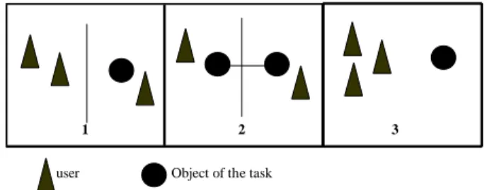
A review of the literature enables us to classify the collaborative AR systems into three categories, as schematized in Figure 1. We first consider the classical distinction in groupware [9], that is the distance between users. We also take into account the distance between one or several users and the object of the task. Because the object and/or its environment is augmented, at least one user must be next to the object or else the system is no longer an augmented reality one and falls into the collaborative tele-operating class.
The first category, namely remote collaboration in one augmented reality, includes systems in which at least one user is physically next to the object of the task and some users are distant. For example in [12] and in [13], two systems dedicated to repairing a physical object, the user is next to the object while an expert is at distant position. The real environment of the user is augmented by information provided by the expert. The second category, namely remote collaboration in augmented realities, encompasses systems where there are several objects of the tasks, remotely linked together and physically present in different sites. Each user performs actions on their own physical object of the task. This is for example the case of a collaborative augmented whiteboard [22]. The real environment (the office with whiteboard) of each user is augmented by information provided by others. Such a system implies that the real environment of each user share common attributes or objects.
The last category, namely local collaboration in one augmented reality, represents systems where all the users are positioned together next to the object of the task. The Shared-Space System [4] and the collaborative Mah-Jongg game [23] are such examples. The users are all together, and the shared physical environment is augmented by information and action from the users. Although they are all together (same physical environment), the key point is that their augmented environments are different.
1 2 3
user Object of the task
Fig. 1. Three categories of collaborative AR systems: (1) remote collaboration in one augmented reality, (2) remote collaboration in augmented realities and (3) local collaboration in
one augmented reality.
2.3 Augmented reality: mobility and groupware
Mobile collaborative systems are rapidly finding widespread use due to the recent progress in networking technology. For example, a new protocol of continuous real time transport between a wireless network and a fixed network such as Ethernet is presented in [17]. This protocol is compatible with the quality of service of the current wireless networks. Moreover the studies carried out by the UMTS consortium [25] foresee, in the short run, flows of data of about 2Mbit/s. Finally hierarchically structured networks combining total networks with local area networks such as Bluetooth [5] constitute a promising approach for providing quality of service in developing CSCW for mobile users. An example of existing collaborative systems is ActiveMap [14] that enables users to locate on a map all participants who carry infrared badges. Another very different example is RAMSES [1], in the archaeology domain. Each archaeologist in the field takes notes on a Palmtop connected to a radio frequency (2 Mb a second) network so that notes can be shared by the group of archaeologists working in the same field.
Although mobile collaborative systems are now possible and systems already exist, and while some existing AR systems are mobile and some are collaborative, few AR systems combine the mobile and collaborative aspects. Mobile and collaborative AR systems combine the characteristics of mobile AR and collaborative AR, in other words:
Definition: A mobile and collaborative AR system is one in which augmentation occurs through available knowledge of where the user is and what the other users are doing.
The only existing system as far we know is the collaborative augmented reality game, called WARPING [21]. Instead of recreating a virtual world, the game is based in the real world, the system only adding the magical possibilities related to the game. Nevertheless the current version of WARPING [21] is not completely mobile - one user being in front of an augmented desktop while the second one makes movements (hand gestures and head) but is assumed to stay in about the same place in front of the walls of the room. But imagine a collaborative AR game, where a participant acquiring new magical powers because of certain actions can see through the walls and discover other participants looking at him. Clearly a role playing game is a great application domain for mobile collaborative AR because the designer can focus only on the magical possibilities, related to the game, that augment the physical world. In the following sections, we will present MAGIC, a mobile collaborative AR system that supports fieldwork carried out by archaeologists. This is another suitable application domain for mobile collaborative AR because:
• The archaeological site is not simulated by the system so we only focus on its augmentation.
• Archaeologists are working in groups in an archaeological site.
• Archaeologists need extra information from databases, from their colleagues working on the site and from experts (such as an expert on water-tanks).
• Archaeologists need information about found objects in the archaeological site. It is important to note that found objects are removed from the site, before starting a new stratum. The exploration of a site is organized according to stratums or levels: the main assumption is that objects, found within a given stratum, are more recent than ones found deeper.
We first give an overview of the MAGIC system, its equipment and infrastructure. We then focus on one user interface component the augmented stroll and its software design.
The design of the MAGIC system is based on a study of the tasks of archaeological fieldwork, from literature, interviews and observations in Alexandria (Egypt). We organized the identified tasks according to the functional decomposition of the Clover Model: Coordination, Communication and Production [19]. The archaeological fieldwork in Alexandria is time-constrained because the archaeological site must be explored in less than three months (rescue archaeology). Tools that can make such fieldwork more efficient are therefore important. To do so the main idea of the MAGIC project is to allow analysis of data directly on the site.
3 MAGIC: equipment and graphical user interface
3.1 Equipment
We base the system on the paper metaphor. We therefore chose a computer whose use resembles that of a note pad or a paper sheet. The pen computer Fujitsu Stylistic was selected. This pen computer runs under the Windows operating system, with a Pentium III (450 MHz) and 196 Mo of RAM. The resolution of the tactile screen is 800x600 pixels outdoor and 1024x768 pixels indoor. In order to establish remote mobile connections, a WaveLan network by Lucent (11 Mb/s) was added. Connections from the pen computer are possible at about 200 feet around the network base. Moreover the network is compatible with the TCP/IP protocol.
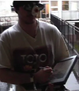
As shown in Figure 2, Augmented Reality needs dedicated devices. First, we use a head mounted display (HMD), a SONY LDI D100 BE. Its semi-transparency enables the fusion of computer data (opaque pixels with a 800x600 resolution) with the real environment (visible though transparent pixels). Secondly, a Garmin GPS III plus is used to locate the users. It has an update rate of one per second. The GPS accuracy is of one meter at the University of Grenoble (France) and of 5 centimeters in the Alexandria archaeological site (Egypt, International Terrestrial Reference Frame ITRF).
Fig. 2. A MAGIC user, equipped with the HMD and holding the pen computer.
On the tactile screen, the location of each user is displayed on top of the site map, allowing coordination between users. The GPS is also useful for computing the position of a newly found object and removed objects. Finally, capture of the real environment by the computer (real to virtual) is achieved by the coupling of a camera
and a magnetometer (HMR3000 by Honeywell that provides fast response time, up to 20 Hertz and high heading accuracy of 0.5° with 0.1° resolution). The camera orientation is therefore known by the system: thus the latter can automatically add the orientation (an arrow to the North) on the pictures taken. (Archeologists used to put a physical rule on the floor showing the north before taking a picture.). As shown in Figure 2, when the magnetometer and the camera are fixed on the HMD, in between the two eyes of the user, the system is then able to know the position (GPS) and orientation (magnetometer) of both the user and the camera.
3.2 User interface on the pen computer
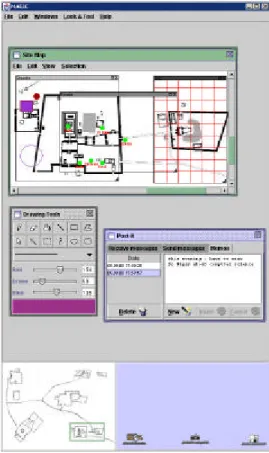
The description of the user interface is organized according to the functional decomposition of the Clover Model: Coordination, Communication and Production. Nevertheless it is important to note that the user interface is not designed according to the Clover Model: indeed some components of the user interface are used for several purposes, such as coordination and production. Figure 3 presents the graphical user interface displayed on the tactile screen of the pen computer.
Coordination: Coordination between users relies on the map of the archaeological
site, displayed within a dedicated window (at the top of Figure 3). The map of the archeological site is the common place of interactions. It represents the archaeological field: site topology, found objects and archaeologists location. Each type of information can be displayed thanks to magic lenses [3] ("grid" magic lens for topology, "objects" magic lens and "users" magic lens). This map is shared by all archaeologists and allows them to coordinate with each other.
The site is displayed in two distinct zones on screen: the detailed site map at the top of Figure 3 and a radar view at the bottom left of Figure 3. The radar view shows a non detailed complete site map. On top of the view, a green frame represents the part of the site detailed in the site map window. Visual consistency between the two parts is guaranteed:
• By scrolling in the site map window (small precise movements), the frame is moved in the radar view.
• By dragging the frame, the part of the site displayed in the site map window is modified. By resizing the frame, the view displayed in the site map window is zoomed in/out.
Resizing the site map window is another way of zooming in/out, the same part of the site being displayed in a bigger/smaller window. We define three levels of zoom for displaying the objects. First the most detailed view enables the user to see all the objects. At the intermediate level, small objects, such as a coin or pottery, are not displayed. Finally, the less detailed view only displays very big objects such a wall or water-tank.
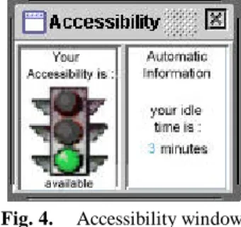
The current position of each user is displayed on the map. A user is represented by a circle. The color of a circle translates the degree of accessibility of the corresponding user. We base the choice of colors on the traffic lights metaphor (green = available for others, orange = can eventually be disturbed and red = do not disturb). The accessibility window of Figure 4 enables the user to set her/his degree of accessibility.
Fig. 4. Accessibility window.
In addition the system must manage the cases of lost network connections. This is for example the case of an archaeologist going inside a water-tank. On the screen of other users still connected, the circle corresponding to the user having lost the connection is stationary (last known location) and blurs progressively. On the screen of the user having lost the connection, all the other users are represented by stationary gray circles, immediately informing the user of the lost connection.
Communication: Three communication tools are implemented. The first one is a
post-it enabling a user to post a note on the screen of another user. Text can be typed in using a transparent virtual keyboard, as shown in Figure 5. Speech recognition is another way of specifying text that we have not yet integrated. A voice recording also supplements the textual post-it so that users can send a voice post-it. The selection of a user (recipient) is made by dragging her/his corresponding circle in the post-it window or by typing her/his name if the user is not inside the site such as for the case of a distant expert. The second tool is a chat room as shown in Figure 5. Again, the specification of the participants can be performed by dragging their corresponding circles from the sitemap window to the chat room window. The last communication tool enables users to share pictures, and discuss them. One example is shown in Figure 5. We use sounds and textual messages displayed on the HMD to keep the user informed of the arrival of a new post-it or request for communication. All the services provided by the mediaspace developed in our team [6] can be incorporated in MAGIC (video and audio communications).
Production: Production covers two complementary activities: describing found
objects and analyzing them. For each found object, archaeologists fill a form describing the object, draw some sketches or very precise drawings and take pictures. In particular, the object must be located in the site (stratum, location and orientation). When an archaeologist describes an object, the description is maintained locally on the pen computer. Using a toolglass, s/he can then validate the new object. After validation, the object is then added to the shared database and is visible on the map of each user. Analyzing objects mainly consists of dating them: dating an object enables the archaeologists to date the corresponding stratum and then continue the fieldwork. Analysis of objects relies on comparisons with known objects from other archaeologists or reference manuals and on discussions with other archaeologists in the site or with a distant expert.
Fig. 5. Human-Human communication tools.
The next section describes the links between the real and the virtual in order to assist the archaeologists in describing objects as well as analyzing them.
4 Augmented Stroll
The virtual world corresponds to all the information maintained by the computer: database of objects, reference manuals etc. The real environment is the archaeological site. In order to smoothly combine the virtual and the real, we create a gateway between the two worlds. This gateway has a representation both in the virtual world on the screen of the pen computer (bottom right part window in Figure 3) and in the real environment, displayed on the HMD.
Information from the real environment is transferred to the virtual world thanks to the camera carried by the user. The camera is positioned so that it corresponds to what the user is seeing, through the HMD. The real environment captured by the camera can be displayed in the gateway window on the pen computer screen as a background. Information from the virtual world is transferred to the real environment, via the gateway window, thanks to the HMD. For example the archaeologist can drag a drawing or a picture stored in the database to the gateway window. The picture will automatically be displayed on the HMD on top of the real environment. Moving the picture using the stylus on the screen will move the picture on top of the real environment. This is for example used by archaeologists in order to compare objects, one from the database and one just discovered in the real environment. In addition the user can move a cursor in the gateway window that will be displayed on top of the real environment. The ultimate goal is that the user can interact with the real environment as s/he does with virtual objects. Based on this concept of gateway between the real and the virtual, we implemented the clickable reality and the augmented stroll. We first describe the clickable reality and the augmented stroll and then focus on their software design.
4.1 Clickable reality
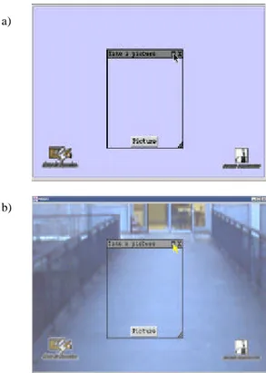
Based on the gateway window, we allow the user to select or click on the real environment. The camera is fixed, on the HMD, in between the two eyes. Before taking a picture, the camera must be calibrated according to the user’s visual field. Using the stylus on screen, the user then specifies a rectangular zone thanks to a magic lens. The specified rectangular zone corresponds to a part of the real environment. As shown in Figure 6, the lens is both displayed in the gateway window on the pen computer and on the HMD. Inside the lens, there is a button for transferring the selected part of the real environment to the virtual world as a picture. A short cut for this action would be a speech command "take a picture" when the speech recognizer will be integrated. The picture is then stored in the shared database
along with the description of the object as well as the location of the object. The next step is then to restore this picture in the context of the real environment: we call this action augmented stroll.
a)
b)
Fig. 6. Clickable reality: (a) Magic lens displayed on the pen computer (b)View displayed on the HMD.
4.2 Augmented stroll
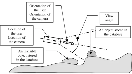
Because a picture is stored along with the location of the object, we can restore the picture in its original real context (2D location). When an archaeologist walks in the site, s/he can see discovered objects removed from the site and specified in the database by colleagues. As schematized in Figure 7, based on the current position and orientation of a user, the system is able to determine the available objects stored in the database whose locations belong to the visual field of the user. The system indicates on the HMD that a picture is available. S/he can then see the object as it was before being removed from the site. The augmented stroll is particularly useful to see objects belonging to a stratum higher than the current one, because by definition the objects have all been removed. We envision to let the user specify what is the stratum of interest, so that the user will only see the objects of a given stratum while walking in the site. The augmented stroll is an example of asynchronous collaboration and belongs to the mobile collaborative AR class as defined in paragraph 2.3.
Location of the user Location of the camera View angle Orientation of the user Orientation of the camera An invisible object stored in the database An object stored in the database
Fig. 7. Augmented stroll.
4.3 Software design
Our software design solution for implementing the augmented stroll draws upon our software architecture model PAC-Amodeus [15]. PAC-Amodeus uses the Arch model [24] as the foundation for the functional partitioning of an interactive system and populates the key element of this organization, i.e., the Dialogue Controller, with PAC agents [7]. Although the software architecture model is not new, we show here how the model, dedicated to the software design of multimodal systems [15], can be applied to the design of an AR system. In particular we highlight the software design of the gateway between the real and the virtual.
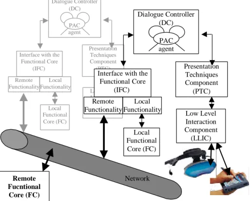
Overall architecture of MAGIC
PAC-Amodeus incorporates the two adaptor components of Arch, the Interface with the Functional Core (IFC) and the Presentation Techniques Component (PTC), to insulate the keystone component (i.e., the Dialogue Controller, DC) from modifications occurring in its unavoidable neighbors, the Functional Core (FC) and the Low Level Interaction Component (LLIC).
Each component of the model briefly exposed before, appears in the design of MAGIC. One instance of the five PAC-Amodeus components is replicated for every user. The PAC-Amodeus architectures communicate with each other via their Interface with the Functional Core (IFC). Indeed all PAC-Amodeus architectures are
linked together via a unique shared Remote Functional Core (FC) that communicates with the IFCs. The IFC maintains links between the Local Functional Core (Local FC) and the Remote Functional Core (remote FC), as shown in Figure 8. In addition the IFC operates as a translator between the database and the data structures used in the Dialogue Controller (DC). The IFC is split into two parts: one that bounds the Local FC with the DC and one that gathers network functionality, and consequently the connection with the remote FC.
At the other end of the spectrum, the Low Level Interaction Component (LLIC) is represented in terms of several components: (1) The JAVA event handler and graphic machine, (2) The augmented reality glasses driver (3) The GPS interface and (4) The electronic compass interface. In turn, the Presentation Techniques Component (PTC) is split into several parts: the PTC is no longer dependent on devices, but translates information from the drivers in terms understandable by the Dialogue Controller. For example, (x, y) positions of the pointer on the graphic tablet are translated into the selection of an object. Remote Fucntional Core (FC) Dialogue Controller (DC) Local Functional Core (FC) PAC agent Presentation Techniques Component (PTC) Low Level Interaction Component (LLIC) Local Functionality Remote Functionality Interface with the
Functional Core (IFC) Dialogue Controller (DC) Local Functional Core (FC) PAC agent Presentation Techniques Component (PTC) Low Level Interaction Component (LLIC) Local Functionality Remote Functionality
Interface with the Functional Core
(IFC)
Network
Fig. 8. The overall architecture of MAGIC.
The Dialogue Controller (DC) is responsible for task sequencing on each user’s workstation. As explained above, the DC is independent of the Functional Core and of the network, as well as of the underlying software and hardware platform, such as the AWT toolkit and interaction devices. The model is geared towards satisfying the
flexibility and adaptability software quality criteria. This component is refined in terms of PAC agents. In the following section, we only describe the PAC agents dedicated to the augmented stroll.
Software design of the augmented stroll
The hierarchy of PAC agents implementing the augmented stroll has been devised using the heuristic rules presented in [16]. In particular we apply the following rules:
Rule 1: Use an agent to implement an elementary presentation object. Rule 2: Use an agent to implement a group object.
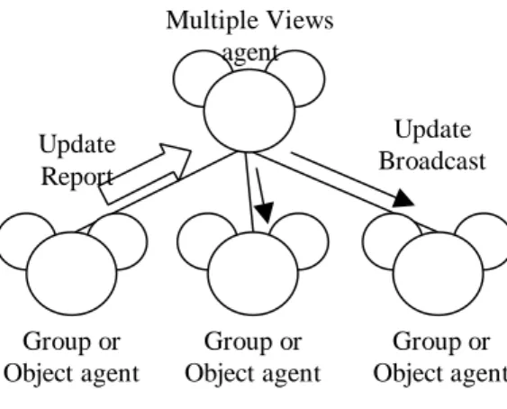
Rule 4: Use an agent to maintain visual consistency between multiple views.
Rule 4 is illustrated by Figure 9.
Update Report Update Broadcast Group or Object agent Group or Object agent Group or Object agent Multiple Views agent
Fig. 9. The Multiple Views agent.
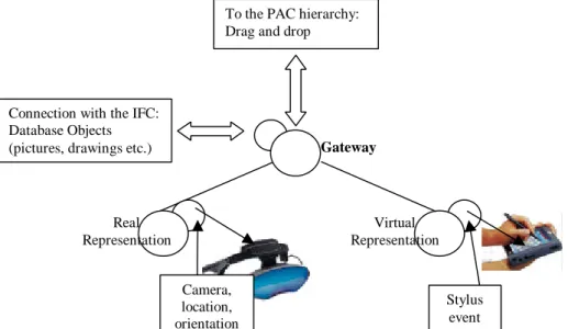
Applying these rules, the augmented stroll is implemented by three agents, presented in Figure 10. One agent called "Gateway" corresponds to the Multiple Views agent and is introduced to express the logical link between the two representations of the gateway: the virtual representation and the real representation. The virtual representation corresponds to one agent, called "Virtual Representation agent". Its Presentation facet implements the gateway window displayed on the pen computer that is presented in Figure 3. The real representation is another agent, namely "Real Representation agent" and its Presentation facet manages the information displayed on the HMD. Any action with visual side effect on a view (Virtual Representation agent or Real Representation agent) is reported to the Gateway which broadcasts the update to the other siblings. To better understand the roles of each agent, we explain the message passing through the hierarchy of agents in the context of the two scenarios: the clickable reality and the augmented stroll.
Real Representation
Gateway To the PAC hierarchy: Drag and drop
Connection with the IFC: Database Objects (pictures, drawings etc.)
Camera, location, orientation Stylus event Virtual Representation
Fig. 10. PAC architecture: combining the real and the virtual.
Real Representation Gateway Virtual Representation M1 (frame) M2 M2, M8 M3,M9 M4, M10 M5, M11 M6 M7 (drag outside the window) M12 M13 (picture, orientation, location) M14 M15 M16 M17 M20 (picture, orientation, location) M18, M19
Fig. 11. Clickable reality.
Figure 11 shows the message passing through the hierarchy of agents in the context of the first scenario: clickable reality. To take a picture, the user has to select what s/he wants to capture using the stylus on the gateway window. It corresponds to message M1. A frame is displayed in the gateway window (M2) and in parallel on the HMD (messages M2, M3, M4, M5 and M6). When the user using the stylus drags the frame outside the gateway window (M7), the Virtual representation agent is asked by the Gateway agent to provide the corresponding picture, orientation and location (messages M8, M9, M10, M11, M12, M13, M14, and M15). The picture is saved in
the Abstraction facet of the Gateway agent (M16). The agent receiving the drop event then asks the Gateway agent for the picture (M17, M18, M19 and M20) in order to display it via its Presentation facet.
Real Representation Gateway Virtual Representation M10 (display the picture) M5 (ask the FC for picture via the IFC)
M2 M1 (location, orientation) M3 M4 M6 (picture) M7 M8 M8 M9 M9 M10 (display the picture)
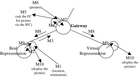
Fig. 12. Augmented Stroll.
In the second scenario, we consider the augmented stroll. While the user is walking, messages specifying the location and orientation (M1) are sent to the Presentation facet of the Real Representation agent from the Presentation Techniques Component (PTC), as shown in Figure 12. Data are passed to the Gateway agent (M2, M3 and M4). In turn the Abstraction facet of the Gateway agent asks the Functional Core if it contains a picture at this point (location and orientation) (M5). If a picture is available, it is received by the Abstraction facet of the Gateway agent (M6). The latter then dispatches the picture to the Real representation agent and the Virtual representation agent (M7 and M8). The picture is then displayed on the HMD as well as in the gateway window on the pen computer (M9 and M10).
5. Summary and future directions
We have presented our definitions and classifications of mobile AR systems as well as collaborative AR systems. These definitions highlight two main characteristics of mobile and collaborative AR systems: "augmentation of the real environment of one
user occurs through available knowledge of where the user is and what the other users are doing". We have then described our MAGIC system whose application
domain is Archaeology, focusing on the mobile and collaborative aspects: the augmented stroll and its underlying concept of clickable reality. For the two concepts, we explained the software design based on the PAC-Amodeus software architecture model. We focused on the software architecture implementing the gateway between
the real and the virtual, a generic software design solution to smoothly integrate the two worlds, without being dependent on the interaction devices.
The next step in our work is to experimentally test MAGIC in order to evaluate the usability of the clickable reality and the augmented stroll. The first tests by archaeologists in Alexandria are planned in June 2001. Although our application domain is Rescue Archaeology, we believe that the clickable reality and augmented stroll are generic concepts that can be applied in other domains such as game: a group of players can for example search for objects that have been virtually placed in the real environment by other users.
Acknowledgements
This work is supported by France Telecom R&D, Laurence Pasqualetti being the supervisor. We wish to thank our partners from the University of Toulouse, P. Salembier and T. Marchand who are currently studying the archaeological fieldwork from a social point of view and the CEA (Centre d'Etude d'Alexandrie in Egypt) for welcoming us. Special thanks to the reviewers for their constructive comments and to G. Serghiou for help with style and English Grammar.
References
1. Ancona, Dodero, Gianuzzi: RAMSES: A Mobile Computing System for Field Archaeology. LNCS 1707, Handheld and Ubiquitious Computing First International Symposium, HUC’99 (1999) 222-233
2. Bauer, Heibe., Kortuem, Segall: A Collaborative Wearable System with Remote Sensing. Proceedings of the Second International Symposium on Wearable Computers, ISWC’98 (1998) 10-17
3. Bier, Stone, Pier, Buxton, DeRose: Toolglass and Magic Lenses: The See-Through Interface. Proceedings of Siggraph’93, Anaheim, Computer Graphics Annual Conference Series, ACM (1993) 73-80
4. Billinghurst, Weghrst, Furness: Shared-Space: An Augmented Reality Interface for Computer Supported Collaborative Work. Workshop Proceedings on Collaborative Virtual Environment (1996)
5. Bluetooth SIG. http://www.bluetooth.com
6. Coutaz, Crowley, Bérard, Carraux, Astier: Using Computer Vision to Support Awareness and Privacy in Mediaspaces. Computer Human Interaction 1999, CHI99 Extended Abstracts Proceedings, ACM, (1999) 13-14
7. Coutaz: PAC: an Implementation Model for Dialog Design. Proceedings of Interact'87 (1987) 431-436
8. Dubois, Nigay, Troccaz,, Chavanon, Carrat: Classification Space for Augmented Surgery, an Augmented Reality Case Study. Conference Proceedings of Interact'99 (1999) 353-359
9. Ellis, Gibbs, Rein: Groupware : Some issues and experiences. In Communications of ACM, 34(1), (1991) 38-58
10. Feiner, MacIntyre, Höllerer, Webster: A touring machine: Prototyping 3D mobile augmented reality systems for exploring the urban environment. Proceedings of the First International Symposium on Wearable Computers, ISWC '97 (1997) 74-81
11. Kangas, Röning: Using Code Mobility to Create Ubiquitous and Active Augmented Reality in Mobile Computing. Mobicom' 99 Seattle, ACM (1999) 48-58
12. Kraut, Miller, Siegel: Collaboration in Performance of Physical Tasks: Effects on Outcomes and Communication. Conference Proceeding of Computer Supported Cooperative Work, CSCW'96, ACM, (1996) 57-66
13. Kuzuoka, Kosuge, Tanaka: GestureCam: a Video Communication System for Sympathetic Remote Collaboration. Conference Proceeding of Computer Supported Cooperative Work, CSCW'94, ACM, (1994) 35-43
14. McCarthy, Meidel: ActiveMAP : A Visualization Tool for Location Awareness to Support informal Interactions. LNCS 1707, Handheld and Ubiquitious Computing First International Symposium, HUC’99 (1999) 158-170
15. Nigay, Coutaz: A Generic Platform for Addressing the Multimodal Challenge. Proceedings of Computer Human Interaction, CHI'95, ACM (1995) 98-105 16. Nigay, Coutaz: Software architecture modelling: Bridging Two Worlds using
Ergonomics and Software Properties. Book chapter of Palanque, P., Paterno, F.: Formal Methods in Human-Computer Interaction. Springer-Verlag: London Publ. (1997) 49-73
17. Pyssyalo, Repo, Turunen, Lankila, Röning: CyPhone – Bringing Augmented Reality to Next Generation Mobile Phones. Proceedings of Designing Augmented Reality Environments 2000, DARE'2000 (2000) 11-21
18. Rekimoto: Navicam: A Magnifying Glass Approach to Augmented Reality. Presence vol. 6, n° 4 (1997) 399-412
19. Salber: De l’interaction homme-machine individuelle aux systèmes multi-utilisateurs. Phd dissertation, Grenoble University, (1995) 17-32
20. Schmalstieg, Fuhrmann, Szalavari, Gervautz: Studierstube: An Environment for Collaboration in Augmented Reality. Workshop Proceedings on Collaborative Virtual Environment (1996)
21. Starner, Leibe, Singletary, Pair: MIND-WARPING: Towards Creating a Compelling Collaborative Augmented Reality Game. International Conference on Intelligent User Interfaces, IUI 2000 New Orleans, ACM (2000) 256-259
22. Streitz, Geiβler, Haake, Hol: DOLPHIN: Integrated Meeting Support across Local and Remote Desktop Environments and LiveBoards Conference Proceeding of Computer Supported Cooperative Work, CSCW'94, ACM (1994) 345-358
23. Szalavari, Eckstein, Gervautz: Collaborative Gaming in Augmented Reality. Proceedings of the Symposium on Virtual Reality Software and Technology (1998) 195-204
24. The UIMS Workshop Tool Developers 1992. A Metamodel for the Runtime Architecture of an Interactive System, SIGCHI Bulletin, 24, 1, 32-37
25. UMTS Forum. http://www.umts-forum.org
26. Webster, Feiner, MacIntyre, Massie, Krueger: Augmented Reality in Architectural Construction, Inspection, and Renovation. Proceedings of Computing in Civil Engineering, ASCE, (1996) 913-919
27. Wellner: The Digital Desk calculator : tangible manipulation on a desk top display. In Proceedings of the fourth annual ACM symposium on User interface software and technology (1991) 27-33