Curved Brick Design Methodology and
Manufacturing System
by
Justin William Carrus
S.B., Mechanical Engineering
Massachusetts Institute of Technology, 2017
Submitted to the Department of Mechanical Engineering
in partial fulfillment of the requirements for the degree of
Master of Science in Mechanical Engineering
at the
MASSACHUSETTS INSTITUTE OF TECHNOLOGY
June 2018
@
Massachusetts Institute of Technology 2018. All rights reserved.
Signature redacted
A uthor ...
...
Department of Mechanical Engineering
May 11, 2018
Signature redacted
Certified by...
Alexander Slocum
Walter M. May and A. Hazel May Professor of Mechanical Engineering
Thesis Supervisor
Signature redacted
Accepted by ...
...
Rohan Abeyaratne
Chairman, Department Committee on Graduate Students
MASSACHUSETTS INSTITUTE OF TECHNOLOGY
MITLibraries
77 Massachusetts Avenue Cambridge, MA 02139 http://Iibraries.mit.edu/ask
DISCLAIMER NOTICE
Due to the condition of the original material, there are unavoidable flaws in this reproduction. We have made every effort possible to provide you with the best copy available.
Thank you.
The images contained in this document are of the best quality available.
Curved Brick Design Methodology and Manufacturing System
by
Justin William Carrus
Submitted to the Department of Mechanical Engineering on May 11, 2018, in partial fulfillment of the
requirements for the degree of
Master of Science in Mechanical Engineering
Abstract
For many people in developing contexts, the financial expense of construction can be overwhelming. There is a need for more appropriate technologies for low-cost con-struction. This thesis presents a concise review of construction technologies and then offers a design methodology for creating curved, interlocking brick geometries that can be produced more accurately than existing bricks. The increase in dimensional accuracy is able to dramatically reduce the cost of construction in developing areas.
A design is then offered for a low-cost press for these brick geometries that can be
produced by local fabricators in developing areas. Thesis Supervisor: Alexander Slocum
Acknowledgments
The author would like to offer a heartfelt thanks to the following people for their contributions to this work: Professor Alex Slocum for his supervision in this project and ever-helpful guidance; the people of PERG for their insightful questioning and inexhaustible curiosity; Thabiso Mashaba and Amy Smith for their endless passion and vision; the D-Lab Botswana students for their desire and commitment to make a difference in the world; the community members of D'kar and Kaputura for their inspiring determination and boundless compassion; the author's family for their un-wavering support and love; and Brittany Bautista for her constant love and patience.
Contents
1 Introduction 15
1.1 M otivation . . . . 15
1.2 Previous Work . . . . 16
2 Background 17 2.1 Traditional Construction in Developing Contexts . . . . 17
2.2 Contemporary Brick Construction for Developing Contexts . . . . 18
2.3 Interlocking Construction Bricks . . . . 19
2.3.1 Curved Bricks at IDDS Botswana 2016 . . . . 20
2.4 The Role of Cement . . . . 21
3 Design 23 3.1 Problem Statement . . . . 23
3.1.1 Deterministic Design . . . . 23
3.1.2 Selection of Compressed Soil Brick (CSB) Technology . . . . . 24
3.2 Analysis of CSB Technology . . . . 24
3.2.1 Pressing Technologies . . . . 25
3.2.2 Brick Characteristics . . . . 31
3.2.3 Analysis Conclusions . . . . 32
3.3 Design of an Accurate Reversible Curved Brick . . . . 33
3.3.1 Design Specification . . . . 33
3.3.2 Brick D esign . . . . 35
3.4 Field Testing . . . . 46
3.4.1 Press Construction . . . . 46
3.4.2 Brick making . . . . 49
4 Discussion 59 4.1 Brick Geometry . . . . 59
4.2 Press Design and Construction. . . . . 60
4.3 Press Operation . . . . 61 5 Conclusion 63 5.1 Future W ork . . . . 63 5.2 Other Implications . . . . 64 5.2.1 Carbon Emissions . . . . 64 5.2.2 Economic Stimulation . . . . 64 5.2.3 Capacity Building . . . . 64 5.2.4 W ater Security . . . . 65 5.3 Final Remarks. . . . . 65 A Press Drawings 67
List of Figures
2-1 Traditional Structure. A house in Botswana constructed in the
tradi-tional style. . . . . 17
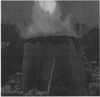
2-2 Firing Bricks. A photo of the brick firing process in Uganda. The standard practice is for a kiln to be erected from unfired bricks. The kiln is then filled with 15 metric tons of hardwood and burned for 24 hours. ... ... 19
2-3 Makiga Brick. An interlocking CEB press created and sold by Makiga[5]. 20
2-4 IDDS Brick. An interlocking brick shape created during IDDS Botswana
2016... ... 21
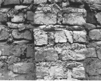
2-5 Mortar in Construction. This photo shows a wall made of fired bricks.
Due to the vast differences in the individual bricks, huge amounts of mortar, and expensive cement, are required[]. . . . . 22
3-1 Typical CEB Press. A brick press that uses a linkage to compress a
brick. This linkage offers an extremely large mechanical advantage[13]. 26
3-2 The Impactor. A brick press design by David Montgomery that
in-cludes a dynamic compaction element . . . . 27
3-3 Brick Directions. Here a canonical brick is shown with the length 1,
width w, and height h directions labeled. . . . . 28
3-4 The Jamming Problem. The jamming problem occurs because the
granular soil is able to transfer shear loads to the walls of the press and results in a lack of compaction at the bottom of the chamber. . . 29
3-5 QMR1-40. A photo of a typical Chinese Manufactured brick press
capable of producing interlocking bricks. This press costs $950 in ad-dition to the cost of shipping from China[12] .. . . . . 30
3-6 Brick press Shipping. A photo of a typical shipping strategy for selling
brick presses in Africa. For large orders, presses are shipped fully-assembled in a single layer[12]. . . . . 30
3-7 Interlocking Makiga Brick. This interlocking brick uses an offset central
element to interlock with neighboring bricks on four sides[3]. . . . . . 32 3-8 Modified IDDS Brick. A simple cut along the centerline allows the
brick to be ejected in a rotational motion about the centroid of the concave face. . . . . 35 3-9 Brick Shapes. These four brick shapes are ejectable and have
inter-locking curved edges. . . . . 36 3-10 Example Wall. This drawing demonstrates how this particular brick
design is able to create straight and curved walls at a variety of curvatures. 36
3-11 Annotated Brick Shapes. These four brick shapes all have issues of some
kind in the highlighted zones. The first, second, and fourth bricks have undercuts and all have thin features. . . . . 37 3-12 Final Brick Design. The drawing shown illustrates the three
con-straints used to create the final set of brick designs. . . . . 38 3-13 Early Press Designs. These drawings show some early designs for
dif-ferent press design strategies. Every strategy consists of a method for compacing the brick and ejecting the brick. The final strategy must do both effectively. . . . . 40 3-14 Final Press Strategy. This set of drawings depicts the final strategy
for the press design. Here, two operators apply forces at the arrows which then propagate through the pinned joints to the flat plate that compresses the brick. Sidewalls and a base support the brick during com paction. . . . . 41
3-15 Labeled Final Design. A solid model of the final design is provided to
establish naming conventions. . . . . 42
3-16 Structural Loop. A drawing of the structural loop of the brick press.
The press shown here is cut down the centerline and two structural loops are shown. The two loops are symmetric, with both being again mirrored by the half of the press that is not shown. The structural loop is kept small to reduce costs and the final mass of the press. . . 44
3-17 FEA for Pressing Chamber. Simulation results for one iteration of
the pressing chamber. Finite element methods were used to simulate the complex geometries within the curved pressing chamber. Here the displacement is shown and is limited to 25 lim. . . . . 45
3-18 Bending Side Walls. Here an angle gauge is being used to measure the
bend angle of one of the side walls of the press. . . . . 47
3-19 Completed Pieces for Testing. Here the pressing chamber, pressing
plate, base, and one lever arm are shown in a completed state. ... 48
3-20 Brick making Steps. The steps to make a brick are shown sequentially
in this graphic. . . . . 51 3-21 Filling the Press. A soil-cement mixture is shoveled into the press. . . 52 3-22 Adding Pressing Plate. The first bit of compression occurs when the
operator places the pressing plate onto the mound of soil in the press cham ber. . . . . 52 3-23 Starting Compression. The bulk of compression comes from the lever
arms compacting the soil. This photo shows the starting position of the levers at the beginning of the compression stage. . . . . 53
3-24 Finishing Compression. This photo shows the ending position of the levers at the end of the compression stroke. . . . . 53 3-25 Brick Ejection. After compression, the brick is ejected using the
han-dles on the press chamber. This version of the brick press uses hanhan-dles placed below the chamber rather than handles on the side. . . . . 54
3-26 Removing the Finished Brick. After ejection, the brick is removed. A
small rotation is all that is needed to dislodge the brick from the base plate and the brick can be lifted away to be laid . . . . 54
3-27 Curved Brick Wall. This photo shows a series of bricks in the curved
configuration. The radius of curvature is set by the brick geometry, but due to the curved nature of the brick sides, bricks can be offset to form new radii of curvature without sacrificing any interlocking capability. 55 3-28 Straight Brick Wall. This photo shows a series of bricks in curved and
straight configurations. By combining sections of curved and straight bricks, one is able to create many different types of structures. ... 56 3-29 Brick Defects. Without the additional operator compression half-way
through filling, the undercuts on the convex brick face suffer from com-paction issues. Understanding this relationship is key to future work on this project. . . . . 57 3-30 Stacked Bricks. The bricks have a significant amount of strength
straight out of the press. This allows freshly made bricks to be stacked immediately. Over the course of several days, the cement in the bricks sets and the brick strength increases to its maximum. . . . . 58
List of Tables
3.1 Brick Dimensions. A delineation of brick dimensions and values. . . . 39 3.2 Component Sizing. A tabulation of key dimensions in the design.. . . 46
3.3 Production Costs. A tabulation of stock and process cost for a one-off
Chapter 1
Introduction
1.1
Motivation
The need for shelter is universal. Shelter for ourselves and our belongings necessitates construction, and for many, the costs of construction can limit access to this basic need.
This problem springs from a combination of factors: the high costs of construction equipment and materials, the lack of financing options, and paltry household incomes. Quantitative data is lacking for the poorest of the poor, but even in Botswana (a comparatively wealthy country to the rest of sub-Saharan Africa) 74% of the rural population lives in self-built housing[2].
This is particularly potent because the issue of construction is directly linked to many other aspects of life. On a personal level, poor living conditions presents issues to health, productivity, and financial security. On a community level, construction, particularly in developing areas, is a leading cause of deforestation. On a global level, construction is one of the largest emitters of carbon dioxide, a problem that will only continue to grow as the world population expands and collectively increases in standard of living.
Improving access to low-cost, quality building materials for use in developing contexts represents both an unsolved and underfunded problem. This thesis proposes one approach to tackling this problem.
1.2
Previous Work
This project directly expands upon work completed in D'kar, Botswana by community members and MIT students from 2015-2018 during student trips and International Development Design Summits. This work will be directly referenced as appropriate.
Chapter
2
Background
2.1
Traditional Construction in Developing Contexts
Traditional construction in developing contexts typically consist of walls built of mud-covered sticks and twigs and roofs of thatched reeds. Figure 2-1 depicts one such structure.
Figure 2-1: Traditional Structure. A house in Botswana constructed in the tra-ditional style.
dam-age from erosion, flooding, high winds, and earthquakes. Even under typical environ-mental conditions, most structures must be rebuilt every 5-7 years[71.
These traditional structures have low capital costs and require less skill/training to erect when compared to a contemporary construction style.
2.2
Contemporary Brick Construction for
Develop-ing Contexts
Contemporary methods for construction most notably include using bricks. There are three main types of bricks: sun-dried, compressed, and fired.
Sun-dried bricks are the easiest and least costly to produce. Often referred to as mud-brick or adobe construction, this type of brick is cast into a mold and allowed to dry in the sun. Of the three types of brick considered in this section, sun-dried bricks have the least compressive strength and are the most prone to erosion. This type of brick requires certain types of soil compositions to have even modest erosion resistance and is often made without the addition of cement.
Compressed earth bricks (CEBs) expand on the sun-dried variety by reducing the moisture content in the raw material and physically compressing the material into a brick shape. CEBs are also known as compressed soil bricks (CSB) and offer more compressive strength and erosion resistance when compared to sun-dried bricks. In most developing contexts, manual brick presses are the only economical option for a producing these bricks. The most common manual brick press is a locally produced variation of the CINVA RAM press originally created in the early 1950s in Bogota, Colombia[10]. This press is simple to make and produces bricks that are suitable for most small houses and walls. This type of brick typically uses a mixture that contains between 5 and 10% cement.
Fired bricks add additional strength to earthen bricks by firing the cast or com-pressed bricks in a kiln. The firing process dramatically increases both the brick's compressive strength and resistance to erosion, but is financially expensive and
en-vironmentally destructive due to the large quantity of hardwood consumed in the firing process. Figure 2-2 shows a standard practice for firing bricks in Uganda wherein a kiln is made of the unfired bricks and then a large fire is maintained within. Each pile burns for approximately 24 hours and consumes 15 metric tons of African hardwood[9]. Fired bricks have cement contents that range from 0 to 20%.
Figure 2-2: Firing Bricks. A photo of the brick firing process in Uganda. The standard practice is for a kiln to be erected from unfired bricks. The kiln is then filled with 15 metric tons of hardwood and burned for 24 hours.
2.3
Interlocking Construction Bricks
A recent development in the field of rural construction is the introduction of
interlock-ing features into construction bricks. These interlockinterlock-ing features typically increase the lateral strength of the wall or reduce the quantity of mortar required during the construction process.
One particularly common example of a brick with interlocking features is the series of bricks produced by Makiga. This Kenyan company offers presses similar to that of the CINVA-RAM, but with an internal shape that allows for bricks to interlock with adjacent bricks on four sides. A photo of a press for such a brick is shown in
Figure 2-3.
Figure 2-3: Makiga Brick. An interlocking CEB press created and sold by Makiga[51.
2.3.1
Curved Bricks at IDDS Botswana 2016
A variation on the traditional interlocking construction brick was developed during
an innovation summit held by IDIN and These Hands in D'kar, Botswana during July of 2016. The design of this brick was motivated by the need for a cheaper method of construction for this village. In the past, traditional roundavals were constructed with a coarse wattle-and-daub style, a method of construction where interwoven sticks are covered with mud. Due to increasing population growth it was becoming more difficult to locate and transport quality materials (large bush trunks, etc.) from the bush to the construction site, increasing the cost of construction. The cost of new construction was particularly important as these traditional roundavals would only last 2-3 years before eroding away.
The village desired a building material that was both stronger than the traditional materials as well as more accessible (low-cost). A group at the IDDS 2016 summit decided upon a strategy of construction that used compressed soil bricks (CSBs) with special interlocking features to allow the traditional round-style of buildings with minimal mortar consumption.
This type of brick, shown in Figure 2-4, was well-received by the community, but was only able to be compressed in the height direction, meaning that under a force-control pressing strategy, the produced bricks were all different heights! Alternatively,
Figure 2-4: IDDS Brick. An interlocking brick shape created during IDDS Botswana 2016.
under a displacement-control pressing strategy, the bricks had different compressive strengths. This distinction is discussed at length in Section 3.2.1.
This compression problem proved difficult to overcome within the project. Careful measurement of the input materials allowed force-control compression strategies to produce acceptably sized bricks, but slowed production to a crawl as each brick had to be meticulously crafted.
Displacement-control strategies also proved less-than-ideal as the production speed also significantly declined when being careful to measure the raw materials precisely in an attempt to reign in the bounds of compressive strength. This issue was com-pounded by the mechanism used for pressing. Whereas presses like the CINVA-RAM are able to reach very large mechanical advantages, they are also quite costly. The mechanism used in the IDDS press was a simple levered press capable of only a 20:1 mechanical advantage.
2.4
The Role of Cement
Cement plays a key role in construction. More formally known as Portland Cement, this mixture of limestone and clay hardens when wet and is a key building material. Its most notable use is in concrete, a cement and gravel mixture.
largest emitter of CO2 globally, contributing between 5 and 7% of total emissions[lj. Furthermore, the industrial nature of the process prohibits production at a local level. In turn, for developing contexts, sourcing and purchasing cement is often the largest financial barrier to construction. In a setting where the cost of labor is negligible, hiring transport and purchasing cement far exceeds other costs.
While cement is often used in the production of the bricks themselves, its more costly role is in the mortar that holds the individual bricks together. The mortar fills voids created by imperfections in the adjacent bricks and bonds with the brick surfaces to transfer loads. Depending on the quality of soil available at the job site, cement concentrations in mortars range from 25 to 40%.
While the mortar is not often of huge concern for modern construction practices, local construction in developing contexts often must use immense amount of mortar to accommodate the wildly varying bricks. A photo of such a wall is shown in Figure 2-5.
Figure 2-5: Mortar in Construction. This photo shows a wall made of fired bricks. Due to the vast differences in the individual bricks, huge amounts of mortar, and expensive cement, are required[1].
In this way, cement plays a huge role in the viability of construction in developing contexts. Reducing the amount of cement required for construction is one of the most powerful ways to make construction in developing contexts more accessible.
Chapter 3
Design
3.1
Problem Statement
Despite the availability of the building technologies described in Section 2.2, housing in developing areas is still dismal at best. The prevalence of issues related to housing poses a potent problem statement. What technology is needed to enable greater access to appropriate housing in developing areas? And furthermore, can this technology be put into practice?
The community interest in the IDDS 2016 brick, despite its shortcomings, was a key influence in setting the direction for this project. Requirements of low-cost, robust brick-making, and curved brick elements were all specifically considered.
3.1.1
Deterministic Design
The design process moved deterministically from a fundamental analysis of brick and pressing technologies to strategies and concepts for both the brick and press. Under-standing the fundamental physics and governing principles allowed more than a single brick design, but rather a whole class of bricks with similar characteristics. Beyond the brick itself, a low-cost press design is offered to demonstrate the potential for this type of brick as well as to complete the design loop and validate the performance and analysis of both the brick and press.
3.1.2
Selection of Compressed Soil Brick (CSB) Technology
The design of an improved brick technology began with the decision to investigate brick technologies specifically. Much prior art exists in the realm of construction technology and brick-related construction exhibits many desirable characteristics in-cluding:" low cost and availability of materials
* strength and durability
" availability of skill for brick-laying
" quick construction
* potential for reduced mortar construction
Furthermore, CSB technology was chosen as an area of particular interest within brick technology due to its desirable characteristics of offering strength and durability relative to sun-dried brick while not requiring the financial or environmental expense of the firing process.
3.2
Analysis of CSB Technology
CSB is a rather established technology, and so, careful analysis of the state of the
technology is essential before hoping to develop new solutions.
At it's core, CSB is defined by its ability to increase the compressive strength and erosion resistance of earthen material through compaction. The key factors in brick strength and erosion resistance are the compaction pressure and the quality of earthen raw material.
The compaction pressure is almost entirely determined by the design of the brick press. It is the press that creates some kind of mechanical advantage to allow the operator to compress the bricks. The relevant physics principles for these machines is discussed at length in Section 3.2.1.
While the quality of the earthen material is very important to the quality of the bricks, any sort of brick and press design exists separately from the supply chain for the raw brick material. Furthermore, often the material is simply the soil that is available naturally at the site of brick production, which is also usually the site of construction.
Much literature exists on the details of what earthen materials make strong bricks, so for the sake of this project, the scope is defined to maximize the quality of bricks for any raw material.
Unfortunately, however, nearly all of these interlocking bricks require compaction along the height direction. This greatly reduces the accuracy and reliability of the bricks when compared with brick designs that can be compressed along the width.
The importance of dimensional accuracy in the height direction is directly driven by a need to reduce the amount of mortar required in construction in an effort to reduce costs and increase accessibility.
3.2.1
Pressing Technologies
A pressing technology enables the operator to form raw earthen material into a brick. Within this task, important considerations are made regarding the pressing force, brick characteristics, and manufacturability of the pressing technology.
Pressing Forces
When considering a press, a key metric is the mechanical advantage offered to the operator during the pressing motion. Most of these low-cost brick presses are indeed manual and require a direct force input from the operator. This is an important metric as brick strength increases with increased compaction pressure.
These manual presses typically offer a mechanical advantage between 10:1 and 100:1. Typical expectations for human output place the maximum operator force at 600 N which equates to a pressing force of 6000 N to 60 000 N.
Figure 3-1: Typical CEB Press. A brick press that uses a linkage to compress a brick. This linkage offers an extremely large mechanical advantage[13.
advantage. This type of press, shown in Figure 3-1, falls into the category of a displacement-controlled press as the increasing mechanical advantage nearly ensures a given compaction displacement. This has the clear advantage of huge pressing forces, but comes at the cost of displacement control, meaning that the press ensures that the bricks are compacted to a particular final size, irrespective of the initial volume of material. This creates problems for the operators as great care must be taken to ensure consistency in the raw earthen materials.
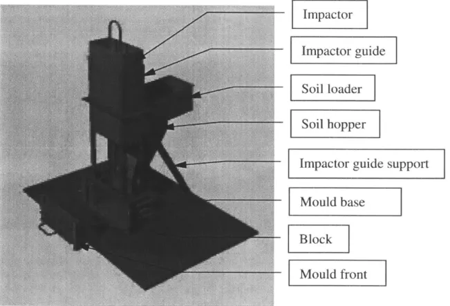
Other types of presses are available, but none see much use. One particularly innovative design in this space is a design offered by David Montgomery that includes an "impactor" of significant mass that is lifted and then released to fall onto the pressing chamber[8]. This design claims a maximum compression force between 12 kN and 43kN.
Pressing Orientation
In addition to the mechanical advantage offered by these pressing machines, an im-portant press consideration is the delivery of that force to the faces of the brick. This delivery is in large part determined by the brick geometry and pressing orientation.
When pressing the brick, it is the simplest, mechanically, to compress along a single direction. Furthermore, as most bricks are rectangular prismatic, they can be
Impactor
Impactor guide
Soil loader Soil hopper]
Impactor guide support
Mould base
Block --- Mould front
Figure 3-2: The Impactor. A brick press design by David Montgomery that includes a dynamic compaction element
reasonably pressed along three directions, length, width, and height as defined for a generic brick in Figure 3-3.
W1
Figure 3-3: Brick Directions. Here a canonical brick is shown with the length 1, width w, and height h directions labeled.
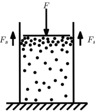
The goal of maximizing compression pressure would push one to compact along the length direction as to minimize the surface area over which the compaction force is distributed. However, the aspect ratio of the brick along this dimension introduces a jamming problem where the granular soil "jams" against the side walls of the press and prevents the bottom of the brick from being successfully compacted. This effect is due to the granular soil transferring a significant shear force to the sidewalls of the pressing chamber. A diagram depicting this effect is shown in Figure 3-4.
This jamming problem effectively prevents compaction from the length direction, so the height and width directions must be considered. Both of these directions feature similar aspect ratios and are mostly immune to the jamming problem.
Importantly, however, the height is a "sensitive direction", meaning that small errors in the dimensioning or parallelness of these faces can lead to severe problems when constructing a wall. The direction that is compacted will be inherently more error prone as the motion stage that compresses the brick will have error motions not found in the rigid press chamber walls.
Additionally, it is desirable to control the force of compaction as opposed to the displacement of compression. This distinction ensures that all bricks will be com-pressed to the same compaction force, a parameter directly related to the compres-sive strength of the brick. If the brick is compressed along the height direction, a
F
0
Fs
0: Z
s-
Fs
Figure 3-4: The Jamming Problem. The
jamming
problem occurs because thegranular soil is able to transfer shear loads to the walls of the press and results in a lack of compaction at the bottom of the chamber.
displacement control strategy must be used to ensure bricks are approximately the
same height.
The width of the brick is largely insensitive. Bricks that vary in width are still able to be formed into walls with almost no downsides. Width compressed bricks
can ensure that the rigid chamber walls maximize the precision of the sensitive
di-rection and avoid the
jamming
problem. Furthermore, width compressed bricks that are compressed using a force-control strategy can produce bricks with more closely regulated mechanical properties.In this way, an optimal press would compress bricks along the width.
Manufacturability
Another aspect on which to evaluate these press technologies are the supply chains that bring the machines to production. Many presses sold in Africa are of Chinese origin and sell for around $1,000. Similarly, the Kenyan-produced Makiga presses start at $1,200[4].
Figure 3-5: QMR1-40. A photo of a typical Chinese Manufactured brick press capable of producing interlocking bricks. This press costs $950 in addition to the cost of shipping from China[12].
Figure 3-6: Brick press Shipping. A photo of a typical shipping strategy for selling brick presses in Africa. For large orders, presses are shipped fully-assembled in a single layer[12.
Upon inspection, these presses have more than 50 individual parts and 40 welded joints. Furthermore, in bulk they can only ship 70 units per shipping container. Given the severe financial constraints on the end users, additional manufacturing optimization could either reduce the cost of the press or increase the revenues seen
by the manufacturer.
3.2.2
Brick Characteristics
Traditional Bricks
Bricks are traditionally 6 sided with three pairs of identical faces. A standard fired brick in the US has dimensions of 3.625 in by 2.25 in by 8 in and is laid with a 0.375 in mortar joint[14].
In addition to the dimensional properties of these bricks, the standard brick is an ergonomically practical unit. Small enough to hold in one hand while laying, but still large enough to quickly build large structures, the traditional brick strikes a balance ideal for bricklayers.
Modern Blocks
Of late, larger brick units have been put into use as a way to reduce costs. Often
referred to as "blocks" rather than "bricks", these units reduce the number of mortared joints in the structure and can reduce both the cost of labor and of mortar. A simple analysis reveals that a double-wide wall of 2x24x24 traditional brick units can be reduced by a factor of eight from 1152 bricks to only 144 blocks. Furthermore, the mortar volume within the wall is greatly reduced. For these reasons, blocks have grown in popularity.
For clarity, the term brick will be used henceforth as a term to describe a discrete building unit of any size.
Interlocking Bricks
New developments, particularly in the field of CEB technology, have pushed additional features into brick geometry. Bricks now often have features to allow for interlocking. Sometimes these interlocking features are meant to be load bearing, other times, the features merely aid in alignment.
Of note in this area are the Makiga Interlocking Bricks. This interlocking brick
system, shown in Figure 3-7, uses an offset center element to interlock with other bricks on four sides. These bricks enable mortarless construction in certain contexts and additionally reduce the skill needed to lay these bricks.
Figure 3-7: Interlocking Makiga Brick. This interlocking brick uses an offset central element to interlock with neighboring bricks on four sides[3.
3.2.3
Analysis Conclusions
Evaluation of the current state of the art provides mixed messages. Presses are capable of generating the required compaction pressures, but are unable to press interlocking bricks in an optimal orientation. Furthermore, these presses are still rather expensive to be considered accessible to the masses.
With these shortcomings in mind, a design for a new type of CSB technology should have the following characteristics:
* reduced need for mortar during construction
" increased production speed
* interlocking features to simplify construction
3.3
Design of an Accurate Reversible Curved Brick
From the feature specifications articulated at the end of Section 3.2.3, a design spec-ification can be created that relates these qualitative requirements down to more quantitative requirements.
3.3.1
Design Specification
Deterministically working from the features specified in Section 3.2.3, the following system-level requirements were identified.
" The selling price of the press should be less than $100
" Less than 100 1m of total error in the sensitive directions
" Production rates should be more than 1000 bricks per 8 hour work day with
two workers
* The brick should have interlocking features that simplifies brick laying
Fundamental principles were then used to further detail these specifications for the design of the brick and press.
Brick Requirements
The brick requirements are as follows:
1. First and foremost, the brick should be compressed and ejected along the width
2. Bricks should be as large as possible to mimic the physical properties of a modern "block", but not too heavy to make handling difficult. A mass of 10 kg was chosen as a suitable goal.
3. Bricks should maintain an appropriate aspect ratio as to avoid jamming. While
more sophisticated analysis into this particular property is necessary prior to mass production, a 1:1 or larger aspect ratio should be maintained between the longer characteristic compression edge length and the depth of compression of the brick.
4. Bricks should be versatile and able to form many different types of structures.
Press Requirements
The press requirements are as follows:
1. The press should cost less than $100 for a consumer to acquire.
2. The press should achieve 3 MPa of compressive pressure within the brick.
3. The press should be able to produce more than 1000 bricks per day given two
laborers and an 8 hour work day.
4. The press should produce bricks that maintain parallelism to within 100 Fm to allow for bricks to be stacked without mortar.
5. The press should not deform or yield under impact loads of 3 times that expected
during normal operation.
6. The press should be portable such that it can move from job site to job site.
7. The press should be easily produced and serviced by a local fabricator.
3.3.2
Brick Design
Brick design evolved directly from the functional requirements. Curved interlocking walls, similar to those found on the IDDS 2016 Brick were highly influential based on the community-support for such a shape. However, for proper ejection, the brick geometry must be modified. A simple modification that allows for this is depicted in Figure 3-8. This alteration demonstrates how a single cut along the centerline can allow for a rotational ejection along the centroid of the concave face.
Figure 3-8: Modified IDDS Brick. A simple cut along the centerline allows the brick to be ejected in a rotational motion about the centroid of the concave face.
A more general geometric constraint on all circular, ejectable, interlocking bricks
would be that:
1. Bricks shall have two curved faces, one convex and one concave, of the same
radius of curvature.
2. The convex face should have a centroid that lies on or beyond the largest planar face.
This geometric class of bricks encompasses all of the designs shown in Figure 3-9 as well as many others.
Bricks that meet the two constraints previously discussed have many interesting qualities. First and foremost they can be compressed and ejected with a simple rotational motion, however, they also enjoy the same interlocking features discussed
ZIYL
71111
Figure 3-9: Brick Shapes. These four brick shapes are ejectable and have inter-locking curved edges.
previously in relation to the IDDS brick. Figure 3-10 shows how these bricks can form straight and curved walls at a variety of curvatures.
( K
Figure 3-10: Example Wall. This drawing demonstrates how this particular brick design is able to create straight and curved walls at a variety of curvatures.
Practical Constraints
While all of these designs interlock to some degree and can be ejected, there are additional constraints that help narrow the scope of brick designs.
First and foremost, the bricks need to uniformly compact. Sharp corners and undercuts at the bottom of the mold should be avoided. Furthermore, the two curved
faces should interlock such that a considerable angular portion of the two interlocking arcs are in contact. This ensure that lateral loads can be transferred. Also, the direction of ejection should not create unsupported, near-perpendicular interfaces. The same bricks shown in Figure 3-9 are also shown in Figure 3-11 with problematic areas annotated.
Figure 3-11: Annotated Brick Shapes. These four brick shapes all have issues of some kind in the highlighted zones. The first, second, and fourth bricks have undercuts and all have thin features.
Final Designs
Taking all of these constraints into consideration, as well as the aforementioned func-tional requirements for brick size and mass, the most promising set of designs was created using the drawing shown in Figure 3-12.
The brick geometry is created from three dimensions, a brick width (A), an arc length (B), and a radius of curvature (C). The brick geometry is then fully con-strained with the following additional constraints:
" The curved faces are required to have the same radius of curvature.
* The flat faces are required to be parallel.
* A normal bisector of either flat face passes through the origin of the path circle.
" The path circle bisects a line drawn between the two midpoints of the flat faces. " The centroid of the convex face lies on the longer flat face.
T
A
-C
Figure 3-12: Final Brick Design. The drawing shown illustrates the three con-straints used to create the final set of brick designs.
Of course, a "height" to the brick is also required and not shown in the drawing. A few additional considerations for selecting suitable values for the remaining
dimensions are as follows:
" Dimension A should be large enough to ensure that walls need not be "double
thick" to avoid required mortar between the wall layers.
" Dimension B should be an integer factor of a full revolution to ensure that a complete circle can be made of an integer number of bricks.
" Dimensions A and B as well as the brick height dimension should be chosen to
ensure compressed bricks do not have a mass larger than 10 kg.
" Dimension C should be chosen to be quite small as to allow for tight bends at
corners and improve ejection characteristics.
Dimension Value
A 6in
B 200
C 24in
Table 3.1: Brick Dimensions. A delineation of brick dimensions and values.
This brick geometry intentionally omits an interlocking feature on the top and bottom brick faces. As seen in Figure 3-7, a keyway of some sort would add to the interlocking nature of the brick. In the case of this brick design, a similar feature was omitted due to the complications such a feature would present during the bricklaying process. Because the brick is compressed and ejected along the width, such a keyway feature would need to cross the brick face, forcing all bricks above and below to be aligned. This dramatically reduces the natural load transfer from brick walls with individual brick layers that are offset. Furthermore, such a feature would add unnecessary expense to any kind of pressing machine.
3.3.3
Press Design
It was then necessary to design a machine to produce the bricks of the previous section. Again, the design process moved deterministically from functional requirements to a completed device.
The functional requirements for the press have been previously articulated in Section 3.3.1.
These requirements drove some initial strategies to be considered that included both rotational and linear ejection strategies. A variety of early designs are included in Figure 3-13.
The final strategy was then chosen based on several key tradeoffs amongst the strategies. The final strategy is shown in Figure 3-14 and uses two operators to simultaneously depress pinned levers to compact the brick. Ejection is accomplished
by lowering the brick chamber.
A solid model of the final design is included in Figure 3-15 for naming conventions
t
~
IT
F
(V
Figure 3-13: Early Press Designs. These drawings show some early designs for different press design strategies. Every strategy consists of a method for compac-ing the brick and ejectcompac-ing the brick. The final strategy must do both effectively.
p
p
Figure 3-14: Final Press Strategy. This set of drawings depicts the final strategy for the press design. Here, two operators apply forces at the arrows which then propagate through the pinned joints to the flat plate that compresses the brick. Sidewalls and a base support the brick during compaction.
Some design motivations for several important tradeoffs and features are included in the sections that follow.
Tradeoff: Rotation vs. Linear
One of the largest tradeoffs when designing the press was the tradeoff between a rotational and linear ejection strategy. The rotational ejection strategy used a simple pin to allow for the required chamber movement, while the linear strategy used a sliding mechanism. The rotational strategy would be more robust as a joint and could allow for a wider variety of brick shapes, but required additional steel to offer stiffness between the center of rotation and the press chamber. Ultimately, the smaller size and reduced cost of the linear solution led to the linear solution being chosen.
Lever Arm Pressing Plate Pressing Chamber Ribs Base Locking Pase PinPlate
Figure 3-15: Labeled Final Design. A solid model to establish naming conventions.
Tradeoff: Single Arm vs. Double Arm
Another key decision related to the pressing mechanism. In most brick presses avail-able on the market today, a single lever arm provides the compressive force for brick compaction. It was observed that it is very rare that a single operator would be producing bricks, and so, a double arm design that allows two operators to simulta-neously compress the brick was used. This decision comes at the cost of an additional component as well as preventing operation with a single operator, but doubled the effective pressing force.
Furthermore, this change balanced the large moment load created by a single operator applying forces to a large lever arm. This change greatly reduces the forces that the press base must withstand which reduces the cost of the press even further.
Tradeoff: Force vs. Displacement Control
As previously mentioned, a displacement control strategy for compaction is not ideal as there is less consistency in the compressive strengths of the bricks. However, many displacement control presses are able to offer the operator a huge mechanical advantage with a linkage mechanism that progressively alters the effective lever-arm of the operator.
The final pressing strategy uses a combination of the two control methods wherein the effective lever-arm of the system is continually increasing, but whereas
displacement-control mechanisms asemtotically approach infinity, the pressing strategy in this de-sign approaches a large, but finite, value. By limiting the effective lever-arm, the brick is pressed with a more predictable maximum force and therefore, will have more predictable mechanical properties.
Feature: Structural Loop
In the chosen strategy, the structural loop passes from the levers to the pressing plate to the brick to the base plate to the ribs to the press chamber walls and then back to the levers. Keeping the structural loop small allowed for further mass and cost
reductions to the press as a whole. A drawing of the structural loop is shown in Figure 3-16.
Figure 3-16: Structural Loop. A drawing of the structural loop of the brick press. The press shown here is cut down the centerline and two structural loops are shown. The two loops are symmetric, with both being again mirrored by the half of the press that is not shown. The structural loop is kept small to reduce costs and the final mass of the press.
Detailed Analysis
To size the components a detailed Python script was used to perform calculations and examine design sensitivities. A simplified script detailing the main calculations for the design is available in Appendix B. By examining the fundamental principles behind the important components, component sizing quickly converged.
Finite Element methods were also used once a basic design had been detailed to verify calculations and model the shell properties of the press chamber. Solidworks Simulation software was used to create and simulate a wide variety of meshes. One example of a mesh and simulation results is shown in Figure 3-17.
URES (mm) 2.456e-OO1 2.251 e-001 2.046e-001 1,842e-001 1.637e-001 1.433e-001 1.228e-OD1 1 .023e-OO1 8.186e-002 6.139e-002 4,093e-002 2.046e-X2 1.0XXe-030
Figure 3-17: FEA for Pressing Chamber. Simulation results for one iteration of the pressing chamber. Finite element methods were used to simulate the complex geometries within the curved pressing chamber. Here the displacement is shown and is limited to 25 jim.
The simulation tools were particularly useful in modeling the stress concentrations seen in the ribs in the bottom of the press. The detailed design includes a particular
geometry that carefully handles the stresses induced from deflections in the pressing chamber walls.
Furthermore, the simulation tools validated an operational factor of safety of 1.5 and a maximum expected load-induced error motion of 25 pm.
A table summarizing the resulting dimensions is provided in Table 3.2. Complete
dimensions in production-style part drawings are available in Appendix A.
Component Value
Press Chamber Wall Thickness 0.375"
Rib thickness 0.1875"
Lever Arm Height 3" with 2" extension
Lever Arm Width 1"
Lever Arm Tube Thickness 0.083"
Lever Arm Pivot Tube OD 1"
Lever Arm Pivot Tube Wall Thickness 0.12"
Lever Arm Tab Thickness 0.375"
Table 3.2: Component Sizing. A tabulation of key dimensions in the design.
3.4
Field Testing
The design was produced and tested in a real-world situation. Detailed documentation of the press construction and operation is included in the sections that follow.
3.4.1
Press Construction
For the construction of the press, an OMAX abrasive waterjet was used to cut the complex side chamber plates and lever arm guides out of 3/8" A36 plate steel. The ribs were also waterjet out of 3/16" plate steel. An angle grinder was used to cut the remaining pieces to size.
To form the curved side plates, a linear approximation of the curve was accom-plished by using an angle grinder to notch the side plates prior to bending by hand in a vice to within 0.20, the angular resolution of a Wixey WR300 digital angle gauge.
Figure 3-18: Bending Side Walls. Here an angle gauge is being used to measure the bend angle of one of the side walls of the press.
care was taken to avoid thermal deformation during welding by using a back-stepping technique. The resulting parts were then checked for fit.
Figure 3-19: Completed Pieces for Testing. Here the pressing chamber, pressing plate, base, and one lever arm are shown in a completed state.
As some of the plates were toleranced to be slightly less than nominal (such as the pressing plate that must slide into the chamber), it was necessary to remove some material from these sliding components. This was quickly accomplished with an angle grinder and a coarse sanding disc.
The notching technique used to bend the side plates had the consequence of in-troducing a void within the pressing chamber. This void was eliminated with filler material by welding the seam and then using an angle grinder to remove any excess from the weld bead.
Information regarding the cost of a single unit of production is included in Ta-ble 3.3 as reference for the stock and processes.
Stock/Process Cost
24" x 12" x 3//8" Steel Plate $54.78
48" x 6" x 3/8" Steel Bar $48.24
48" x 3" x 1" x 0.083" Rectangle Steel Tube $34.52
48" x 2" x 1" x 0.083" Rectangle Steel Tube $18.12 24" x 2" x 2" x 0.083" Square Steel Tube $11.72
12"x 12"x 3/16" Steel Plate $14.94
12"x 1"x 0.12" Steel Tube $9.46 6" x 1" Steel Round $2.59
12" x 3/8" Steel Round $1.62
Waterjet Consumables $80.00
Angle Grinder Cutoff Wheels $5.00
Welding Consumables $5.00
$285.99
Table 3.3: Production Costs. A tabulation of stock and process cost for a one-off production. In total, the one-off production cost came to $290.
Mass Manufacturing
While many design changes will certainly be necessary before a production run of this press, the press was designed with at-scale production in mind.
In a production setting, the side walls, lever arm tabs, and bearing plates would not be waterjet, but rather CNC plasma cut. The curved sidewalls would be sheared to length and then bent in a die to the desired curvature. All of the other pieces would be purchased at the proper width and thickness and sheared to length. These pieces could then be flat packed and shipped economically to a local fabricator who could assemble the press with only a stick welder and angle grinder.
While it would be futile to try to estimate the cost of a mass production model, a crude estimate can be made given the assumption that mild steel products can be produced for around $1 per kilogram of product. Given that the current design of the press contains 29 kg of mass, an estimate for the raw material costs for a future product would be in the range of $30 to $50.
3.4.2
Brick making
1. Pin the pressing chamber in place.
2. Half fill chamber with soil-cement mixture (approximately 1 shovel)
3. Compress the soil-cement mixture by hand into the lower corners of the
cham-ber.
4. Fill the chamber with the soil-cement mixture (approximately 1 additional shovel)
5. Use the pressing plate to compress the contents of the chamber to the top edge
of the chamber by hand.
6. Both operators slide the lever arms into place.
7. In a concerted effort, depress the levers, compressing the brick.
8. Remove the levers, the pressing plate, and the pin.
9. Impact the top of the side walls with a mallet to cause the brick to "break free". 10. Use the handles to lower the pressing chamber and eject the brick.
11. Remove and place the brick.
12. Use the handles to raise the chamber and pin in place.
13. Repeat.
A diagrammatic depiction of the necessary steps are shown in Figure 3-20. Photos
Figure 3-20: Brick making Steps. The steps to make a brick are shown sequen-tially in this graphic.
(2)
100,
0
Figure 3-21: Filling the Press. A soil-cement mixture is shoveled into the press.
Figure 3-22: Adding Pressing Plate. The first bit of compression occurs when the operator places the pressing plate onto the mound of soil in the press chamber.
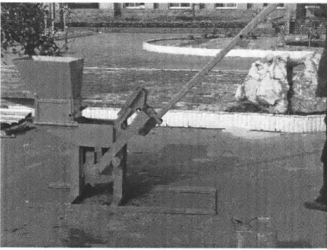
Figure 3-23: Starting Compression. The bulk of compression comes from the lever arms compacting the soil. This photo shows the starting position of the levers at the beginning of the compression stage.
Figure 3-24: Finishing Compression. This photo shows the ending position of the levers at the end of the compression stroke.
Figure 3-25: Brick Ejection. After compression, the brick is ejected using the handles on the press chamber. This version of the brick press uses handles placed below the chamber rather than handles on the side.
Figure 3-26: Removing the Finished Brick. After ejection, the brick is removed.
A small rotation is all that is needed to dislodge the brick from the base plate
Figure 3-27: Curved Brick Wall. This photo shows a series of bricks in the curved configuration. The radius of curvature is set by the brick geometry, but due to the curved nature of the brick sides, bricks can be offset to form new radii of curvature without sacrificing any interlocking capability.
Figure 3-28: Straight Brick Wall. This photo shows a series of bricks in curved and straight configurations. By combining sections of curved and straight bricks, one is able to create many different types of structures.
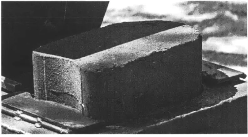
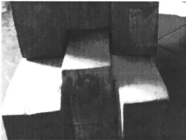
Figure 3-29: Brick Defects. Without the additional operator compression half-way through filling, the undercuts on the convex brick face suffer from compaction issues. Understanding this relationship is key to future work on this project.
Figure 3-30: Stacked Bricks. The bricks have a significant amount of strength straight out of the press. This allows freshly made bricks to be stacked immedi-ately. Over the course of several days, the cement in the bricks sets and the brick strength increases to its maximum.
Chapter 4
Discussion
A detailed assessment of the system is included in the sections that follow.
4.1
Brick Geometry
The brick geometry was appropriate for building with a size that was considerable but manageable. The brick was large enough to build quickly, but small enough to still carry by a single operator. The curvature was suitable for structures the size of a single room dwelling and smaller. The brick had an appropriate width such that a single thickness or bricks was suitable for building a structure.
However, the bricks struggled with jamming problem in the bottom-most corners, which is why the process had to expand to include a step that "hand compressed" the brick into the corners halfway through the filling process. This is less than ideal as this problem hints at compaction issues in the brick, reducing the structural integrity of the produced bricks. This problem is noted in many similar presses such as the Makiga Press
[6]
where users are suggested to use a stick or hand to compress the brick into the bottom corners prior to complete filling and the final compression. Further investigation is needed to see if this issue is purely cosmetic or if the issue destroys the structural integrity of the entire brick. If cosmetic, it is advised that the brick geometry not be changed as a cosmetic flaw is far less an issue that the potential to need a double-thick wall. However, if the structural integrity is damaged, reducingthe width of the brick will be necessary.
4.2
Press Design and Construction
Detailed analysis of the quality of bricks able to be produced by the press is still in progress as the results will vary with the type of raw material used in the press. However, discussion of the progress of this brick press prototype towards the initial functional requirements is possible.
The press design is quite simple, which lends itself well to keeping costs low and serviceability high. Initial estimates seem to indicate that an end-user price of less than $100 is possible with the right supply chain and partners.
Analysis and simulation shows that errors from load-induced deformations (25 1im) are well under the goal of 100 um, however systematic errors due to manufacturing errors have yet to be accounted for as many presses will have to be made and mea-sured.
A realistic estimate for compaction pressures would place the designed press at 75% of the 3 MPa goal. Increasing the compaction pressure would be as simple as
increasing the length of the lever arm tubes, however modifications to those dimen-sions will wait until further testing on the compressive strengths of the produced are established.
The press is quite portable, and at only 29 kg is almost half the weight of a Makiga press. Careful treatment of the structural loop was critical for keeping the mass of the system low.
In terms of fabrication, the construction of the press was straightforward. The biggest fault was that welding the lever arm was complex with the lever arm tabs being difficult to fixture in the proper orientation. Future versions should include more locating features or a separate tool to fixture things in place during the welding process.
4.3
Press Operation
The press operation had several issues. First and foremost, the previously mentioned issue with compaction should be remedied. Additionally, the pin was difficult to insert while also supporting the pressing chamber. A small spring to automatically lock the chamber in place would add quite a lot of functionality for a small cost and should be seriously considered in future designs.
Furthermore, the chamber was difficult to release from the brick without an impact force. Future designs should either include some sort of mechanism to start the ejection process or note the need for a set of mallets in the operating instructions.