READ THESE TERMS AND CONDITIONS CAREFULLY BEFORE USING THIS WEBSITE. https://nrc-publications.canada.ca/eng/copyright
Vous avez des questions? Nous pouvons vous aider. Pour communiquer directement avec un auteur, consultez la première page de la revue dans laquelle son article a été publié afin de trouver ses coordonnées. Si vous n’arrivez pas à les repérer, communiquez avec nous à PublicationsArchive-ArchivesPublications@nrc-cnrc.gc.ca.
Questions? Contact the NRC Publications Archive team at
PublicationsArchive-ArchivesPublications@nrc-cnrc.gc.ca. If you wish to email the authors directly, please see the first page of the publication for their contact information.
NRC Publications Archive
Archives des publications du CNRC
This publication could be one of several versions: author’s original, accepted manuscript or the publisher’s version. / La version de cette publication peut être l’une des suivantes : la version prépublication de l’auteur, la version acceptée du manuscrit ou la version de l’éditeur.
Access and use of this website and the material on it are subject to the Terms and Conditions set forth at
Photogrammetric measurements of deformations of structures
Moser, C.; Schriever, W. R.
https://publications-cnrc.canada.ca/fra/droits
L’accès à ce site Web et l’utilisation de son contenu sont assujettis aux conditions présentées dans le site
LISEZ CES CONDITIONS ATTENTIVEMENT AVANT D’UTILISER CE SITE WEB.
NRC Publications Record / Notice d'Archives des publications de CNRC:
https://nrc-publications.canada.ca/eng/view/object/?id=31a0dc34-e4f8-44ca-907c-b61beff2f178 https://publications-cnrc.canada.ca/fra/voir/objet/?id=31a0dc34-e4f8-44ca-907c-b61beff2f178
R I L E M
R C u n i o n I n t e r n a t i o n a l e d e s L a b o r a t o i r e s
-
d'Essais sur les MatCriaux e t les Constructions C A N A D A C o m m u n i c a t i o n p r e s e n f d e a u Symposium sur I ' O b s e r -vation des O u v r a g e s realis6 au Laboratorio N a c i o n a l
T H E M E
1
d e Engenharia C i v i l - L i s b o a - P o r l u g a l e n O c t o b r e 19551
aj
i p r e u v e d e r e p r o d u c t i o n i n i e r d i l e iPhotogrammetric measurements
of
deformations of structures
C .
MOSEI?
D I I ~ I . h4arh. Di\.ision of Applicil Pli\.sics
W . R. SCHRIEVER
Dip]. Engincrr. Division of Building Rc~c.~rcli NATIONAL RESEARCH COUNCIL. OTTAWA
1. Introduction
Photograinmetric inethods crt~l be s~~cccssfully npplied not onlJ. to mapping but also to problems in which shape or dimensional changes of a n object must be determined. O n e broad field of application of photograminetric methods in this regard is the determination of deformation in structures. T h e main adva~ltage of the photogrammetric method is that all ~neasurements are ~ l l a d e from photographs which are simple to make coillpared to other measure- IIICII~S. T h e necessary deformation data arc afterwards obtnined in t h e office and are reproducible at any time.
T o determine the degree of npplicability of the photogrammetric method
LO the above-mentioned problems, esperiments were carried out by the D i v i s i o ~ ~
of Applied Physics in co-operation wi,th the Building Research Division of the National Research Council of Caanda. Prior to these experiments soille iavesti- $ations were carrled out to determine thc order of accuracy which could
LC
expected in appl!iing the photogrammetric method to thc determination of deformations. T h e present paper describes this work and deals generally with [he advnntnges and disadvantages of the method.A
sulnmary on photogramlnetr~c measurements of deformations has beenin a book
bj,
0.
L A C ~ , ~ ~ \ N N
I .All.
papers quoted on this subject byLACS~ANK
were published at least twenty , , years ago in periodicals on photogrammetry ands~lrveving. A s these papers are not readily available and much progress has been nlacle since in photogrammctric research it is thought that the methods of pho- togra~llnletric ~neasurements of deformations should be brought to the attention of civil engineers.
T h e method has many advantages over [he more conventional means oE measuring deformations of structurez s ~ l c h as dial gauges, taut wijres and level surveys. N o supporting system for dial gauges or p ~ ~ l l e y needs to be installed and the loss of time connected with S L I C ~ a system, as well as the necessity for
taking individual readings at all desired locations, is completely eliminated. Moreover, the photogra~nmetric mithod allows the determination of t h e defor- mation of the structure at any desired location visible on the T h c need to choose all essential me~isuring points of the structure before t h e test is also eliminated. T h e method is particu1a1-jr well suited for plane structures such as beams, trusses, and frames.
2. Description of methods
There are two methods that may be used for the determination oE deformation: the single camera method and the two camera mcthod. In the single c:uiiera method, single photographs are takel; at the desired times. T h e measurements, however, are deterlnined from pairs of single photographs. T h e way this is done will be discussed in detail later in this report. Measurements
by
the t w o camera nletllod are based on the use of s t e r e ~ ~ h o t o ~ r a ~ h s of the object. I n both methods ordinary fine grain plates are used, wliich :ire processed wit11 afine-grain developer to
medium
contrast.T h e single carnerd riethod
A
single photogrammetric calllera is setLIP
in sucll a way that t h e optical axis is app.1-oximately norlllal to the ~ n a i n plane of the object.A
first photograph is made of the test object in its undeformed state. Further photographs are then taken as the structure is defornledby
the applied load. T o evaluate thedeformation
the first photograph
i;
combined with any succeeding photograph. T h e evaluation is done in a stereo-comparator or in a stereo-a~~tograph, which are stereoscopic instruments for measuring parallaxes and co-ordinates of inlage points. Both negatives are placed on the photo carr~ers of the instrument and after due orientation the observer can see a three-din~ensional optical nlodel of the photographed object. T h e parallax is ~lleasured opticallyby
placing a floating mark (e.g.
black dot)on the surface of the optical model. T h e shift of the floating mark from a reference plane to a point on the surface of t h e optical model is eq~lal to t h e parallax of that point.
For the lneas~lrement of the
deflections
of a beam, for instance, both negatives-
are rotated on the photo carriers u n t ~ l t h e beam appears to be In a vertical position. T h e n the photoura11
of the undeflected beam and that of the deflected beam. a.
p
form a stereopalr In which the deflection appears as a horizontal parallax, that is, the observer sees a stereoscopic optical lnodel of t h e beam in which parts not affected by the deflection show no parallax and, therefore, appear t o lie in one
lane.
whereas those Darts of the beam which are deflected show a horizontal1 1
parallax and appear to be bent towards or away from the observer. T h e floating mark is then placed on every surface point of the optical model in which t h e deflection is to be determined. T h e ooints which define the reference line 1 for deflection measurements (e.
g.
t h e ends of a beam) must be visible on t h e photoora 11s. T h e measured parallax is used to calculate the deflection in t h e?
p
direct1011 nor~nal to t h e reference line.
T h e main advantages of the single camera method are: 1. Only one photo,orammetric camera is required.
2. T h e orientation of the negatives in t h e stereo plotting machine is simple.
3.
T h e determination of a deflection in a plane parallel to the plane of the pl~otographic plate is sinlple and precise.Possible disadvantages of this method are:
1. O n l y deflections in planes parallel to t h e plane of the photographic plate are measureable.
2. T h e outer orientation of the camera must be maintained accurately during t h e experiment.
TWO
camera methodT w o pl~otogrammetric cameras of the same optical characteristics are placed in a known external orientation at an appropriate distance from the object to be photograpl~ed. In the simplest case the optical axes of the calneras are parallel t o each other, horizontal and normal to the line joining their stand points called the base. I n special stereornetric calneras t h e abovementioned conditions are met. T h i s equipment is con~posed of two identical calneras mounted rigidly at the ends of a metal tube in such a way that their optical axes are parallel to each other a n d perpendicular to the base. However, two separate callleras can also be used with t h e advantage of allowing a choice of base length appropriate to the object and to t h e desired accuracy.
In using this equipment for the determination of deformation, the stereo- metric camera can be placed in an arbitrary position relative to the object, but for the sake of simplicity in evaluating the photographs, it is preferable to have the principal axes of the cameras approximately normal to the main plane of the object. For the measurement of deformation pairs, of pl~otograpl~s are made at various stages
Fig. 1
Pl~ototl~eodolite
of deformation of the structure. Whereas in the single camera method a stereo- comparator can always be used, in the two camera method the use of a stereo- autograph may lead to a simpler evaluation of the photographs, since the stereo- autograph allows the exact reconst.ruction of the optical nlodel of the object and the establishment of the absolute orientation of the model by optical-mechanical means. A n y necessary measurements can then be made on this optical model.
T h e results of these measuremeilts are given in spatial co-ordinates. From these co-ordinates any required length or direction measurements can be derived.
T h e main advantages of the two camera method are:
1.
A
stereopair allows deformations in any direction to be determined. 2. Since both photographs are made simultaneously, also moving objectsmay be photographed.
3.
For the same reason, lightinu conditions are identical in each photo-? .
graph of a stereopair; this f a c ~ l ~ t a t e s their use in evaluation operations.
Fig. 2
Stereometric camera. Base 1.20 m
Possible disadvantages of this method are:
1. T h e two camera method requires the use of more equipment. 2. T h e relative orientation of the cameras at the moment of exposure
must be known with high accuracy.
Discussion of application of methods
W h e r e deflections in a single plane or possibly in parallel planes must be measured, the single camera method can be applied if it is possible to place the optical axis of the camera a p p r o x ~ r n a t ~ v e l ~ normal to the plane of deflection. If this cannot be done, or if deformations i n three dimensions are required, the two camera method must be used.
I n the single camera method the orientation of t h e camera must be maintained during the test. T h i s can be done conveniently with a photo-theodolite (fig. 1).
A
photo-theodolite is a ground surveying i~lstrument combining a theodolite and a photogramme~ric camera in which the relationship between t h e position of the camera axis and the axis of the theodolite telescope can easily be ascertained. T h u s the orientation of the camera can be maintained or re-established by resectio~t from known fixed points.In this paper experiments with the single camera method only are reported. 3. Examples of application
a)
Simple
beamI n order to determine the accuracy and the effect of distance on the accuracy of the sitlgle camera method the deflections of four equally sized and loaded wooden beams were measured p l ~ o t o g r a n ~ n ~ e t r i c a l l ~ and with dial gauges. T h e four beams were placed at distances of 9.0, 18.1, 36.4 and 73.0 nl fro111 the photo-theodoIite.
Fig.
3
shows the arrangement of the beams.Fig. ;
Woodell beams under load
T h e pl~oto-theodolite used was equiped with a camera having a calibrated fixed focal length of 168.07 111111 and an image size of 1 0 by 15 cm.
A
first photo-ora h was made of the beams without load and a second one was made with loads
3 p.
applied.
In~~llediately before exposure the dial gauges were read. T a b l e 1 shows the deflection at the centre o i the four beams. T o obtain con~parable results, vertical movements at the supports caused by the applied load have been taken in account.TABLE
1Deflections obtained by photogrammetric and conventional method
Beam 1 1 . '
i
s
A
Distance (m) to the beam 9 18.1 36.4 73.0
1
-- -- -- Scale of photographs 1:54 1:108 -- - -Deflection (mrn) - -by dial gaugeThese rcsults will be discussed in detail in art.
4.
b) Railway
t m c kAs another example the deformation of a rail under a nlovlng wheel load was determined. T h e same photo-theodolite as in examplc a) was placed normal to a railway track at n distance of 8.25 m. T h e optical axis of the i ~ l s t r u m e ~ ~ t was set approximately normal to the track in a horizontal pos~tion. T h e first photograph was made while the track was free. T h e second photograph was made with an exposure of I / 100 s when the front wheel ol a n ensine was about in the middle of the lield of view as shown in
tisv.
4.
Fig. 4
T h e deflection of the track was determined in the same way as in example a).
Fig.
5
shows the deflection of the rail.Fig. 5 Deflection of rail
C) Concrete bridge beam
During the construction of a new bridge across the Rideau River in Ottawa the deflection of a prestressed concrete beam under a load of 7.5 t was deter- mined with the single camera method. Since the river made it difficult t o measure the distance from the photo-theodolite to the beam bv direct method, a series of markers were mounted at exactly equal intervals at the upper edge of t h e beam.
TIILIS
the ratio between the actual length of an interval and the correspond-Fig. 6
Concrete beam under load
ing length on the negative determined t h e ratio between the measured parallax and the actual deformation.
Fig. 6
shows the loaded beam andfig.
7 is a diagram showing the deformation of the upper edge of the beam.t:m
D
Fig. 7
Deflection of concrete beam under load
d)
Wooden roof trassA s part of its work in housing research the Division of Building Research carried out a loading test on two wooden roof trusses in their structural laboratory. This test was used as a further expzriment in the measurement of deformations of structures by the photogrammetric method.
A
photo-theodolite was placed i n front of the W-truss at a distance of I1 m. T h e orielltatioll of the principal axis of the camera was checlcedby
theodolite readings on two special sighting taroets. Photographs were taken after application of various increments of load?
during
the test.From these pl~otogr~apl~s any desired deflection and rotation of any member, of truss could be determmed.
Fig.
8 is a front vicw of the wooden roof truss.Fig. 8
4. Theory and accuracy consideration
T h e accuracy of measurements depends on a nurnber of factors, the most important of which are: the scale of the photographs, the definition of the photo- oraphic image, the skill of the operator 111 the evaluation of the photographs, and 3
In case of the two calnera method the identity
06
optical characteristics of the two cameras and the ratio between the distance to the photographed object and the base (known as the base ratio). In the followi~lg the theoretical accuracy of the two methods will be considered.Single cnmern method
Referring to fig. 10 a bearm
AB
is clamped atA .
If
a plane force is applied, say inB,
the beam will deflect in a vertical planeX
-Z.
i z l
Fig. 9
Principlc of single camera mcthod
A t a !given distance
Y
fro111 the bean1 a photogrammetr~c camera is set with the principal axisCH'
normal to the beam.C
- centre of perspective. T h u sthe
X'
-2'
plane of the photographic plate becomes parallel to theX
-Z
plane.A
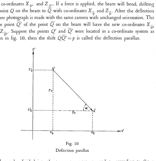
pl~otograpl~ of the undeflected beam is made and a n y pointQ
on the beam with the co-ordinatesX
andZ
is imaged to pointQ'
of the photographic platewith co-ordinates X Q , and
Z
Q,.If
a force is applied, the beam will bend, s l ~ i f t i n ~ the pointQ
on the beam toQ
with co-ordinates X- andZ-.
After the deflectioilQ Q
another is made with the same camera with unchanged orientation. Th: image point
Q
of the point Q o n the beam will have the new co-ordinates X- 0' andZ-
. Suppose the pointsQ'
andQ'
were located in a co-ordinate system as0'
shown in
fig.
10, then the shiftQQ'=
p
is called the deflection parallax.Fig. 10
Deflection parallax
Let
p
be divided into the two componentsp ,
andp,
according to the .uand z direction, then it is easy to see that for the deflection 1n the x-direction
and for the deflection in the z-direction
with
C.1G
T h e angle of deflectioil with reference to the x axis is determined by
PI tan o: = -
.
P x
Equation (3) shows that the actual deflection in the
X
-Z
plane can be calculatedif
the parallaxp
and the distancesY
andf
are known.T h e distance
Y
from the lens to the beain can be measured with a tape and the quantityf,
ltnown as the camera constant, is engraved on the camera by the manufacturer, thus the ratioY l f
becomes a constant scale factor:Because of this it is not necessary LO measure the distance
Y.
Instead, a ltnowndistance
L
between two points on the object can be used. LetL'
be the length of the image ofL
on the pl~otograpl~ic plate. T h e n the scale factor becomes:Thus the resultant deflection becomes:
D = M p .
This procedure has been followed in examples 3a, 3b and 3c. (Notice scale in front of the railway track in fig.
4).
Finally the parallax remains to be measured. This can be done accurately by means of a stereo-conlparator or a stereo-autograph which is used for mapping in terrestrial and aero-photogrammetry.
If
both pl~oto,oraphs are placed in a stereo-auto,oraph and oriented so that either the conlpollelltsD ,
orD,,
or the resultant deflectionD
are changed into a hori--
zontal parallax, a three dimensional optical model of the test object in a predeternl- ined scale can be seen. In this opticai model all parts of the object which were not affected by the deflection appear to lie on one plane while those parts of the object which have been deflected appear to be bent towards or away From the observer. Thus the componentsp,
orpL
orp
can be measured.From equation
( 3 ) the error
d D
of the deflectionD
follows:In most practical applications
p d Y
<<
Y dp,
hence the second term in the bracket can be neglected. T h u s (7) becomes:Example
3
b:A
scale of the lengthL=
2m was mounted on the rail. T h e lengthL'
on t h e photographic plate becameL'=
40.00 mm. T h e mean error of the readingp
isdp
=A
0.005 mm. Hence,2000
dD
= --40 0.005 =
f
0.25 mm.T h e maximum deflection of the rail was 11.70 m m , thus the mean error of deflec- tions is 2.14
%
ofD
maximum.T o check the accuracy of photogrammetric measurements reference is made to the first example of applications. Four simple beams equally loaded were set at distance Y, = 9.0 m , Y, = 2 Y
,,
Y, = 4Y, and Y, =8Y,. T h e mean errord p
of a single parallax measurement derived from several series of observations 1s
A
0.004 mm. In the third row of Table 2 the errorsd D
of deflectionD
a s calculated from equation( 9 ) are listed. T h e last row shows the difference
AC
between
the photogrammetric measurements and the readings of the dial gauges.TABLE
2
Calc~~lated Errors and Measured Differences at Distances
YI
to 8Y1- - - --
AD
(mm)1
I0.56
+
0.20
2.46+
0.96
(from Table
I )
1
-1
I----
I
-
I
T h e agreement between the photogrammetric and direct determination of deflection is good. In examinins the results shown in Table 2, it must be borne in mind that the accuracy of determining the deflection depends not only on the accuracy of parallax measurement and the distance but also on the accuracy of superimposition of the reference lines in the two photographs. This last operation has, in this experiment, also been affected by difficulties in interpretation; that is in defining the actual points of support of the wooden beams. T h i s would n o t have been the case,
if
roller suppor;s had been used.It
is also probable that part of the somewhat erratic differences between the photogrammetric and dial gauge measurements are due to a twisting of the beams resulting in a decrease of relative accuracy of the dial gauge readings taken along the centre line of the beams.T w o cameTa method
T o explain the principle of this method the simplest case of stereo-photouram-
D.
metrv shall be considered only. In chis case both camera axes and the base Ile in one horizontal plane with the camera axes parallel to each other and normal to the base.
Fig. 11
Principle of stereo camera
Referring to
fig.
11Let
Q
- object point0,
- centre of perspective of the left camera0,
-
centre of perspective of the right camerab
- base-
f
-H ' ,
0,
=H ' ,
0,
= camera constantQrL
- leftimage
point with co-ordinatesX,, Z,
Qr,
-
right image point with co-ordinatesX,,
Z,?p
-
X,
-
X,
= parallaxIf
tlie photographs are evaluated in a stereo-autograph no computation is ilecessary to find the co-ordinatesX,
Y ,
Z.
T h e co-ordinates of any pointQ
which appears on both photographs can be read directly.1. T h e error of measuring the horizontal component of deformation, parallel to the axes of the cameras, is derived from the second equation of (10):
Using photogrammetric cameras df may be considered to be 0. T h e error
d b made
in mea~urements of the baseb can also be neglected as it is generally possible
to determine t h e base with an accuracy of 0.02%.
T h u s equation (11) reduces to:Equation (12) shows a decrease of
dY
if
the baseb increases. I n practical applica-
tion equation (12) is used to determine the base for a required accuracydY:
Example: T w o photo-theodolites are set at a distance
Y =
1 0 m from a struchlre. T h e camera constants of both cameras aref
= 150.00 mm. T h e operator of t h e stereo-autograph is able to read the parallaxp
with an errordp=
h O . 0 0 5 m m .If
an accuracydY
=h
0.25 ~ I I I I is required the base becomes:2. T h e error of nleasuriilg the vertical conlponent of deformation is derived from the third equation in (10) :
Let
Z
- ordinate of an object pointQ,
z - corresponding ordinate measured on t h e negative.
T h e n the error of measuring the vertical coinponent of deformation becomes:
T h e mean error of the z measurement may be assumed to be dz= h 0 . 0 0 5 mm to
&
0.01 m m .5.
Practical considerationsFor successful application of photogrammetric methods some consideration should be given to practical details.
T a r g e t details
In the evaluation of the photographs in a stereo-autograph or in a stereo- comparator a ((floating mark)) has to be visually placed by the operator on surface points of the three-dimensional optical inodel of the test object. Usually the floating mark is a black dot. O n parts of the test object where the contrast between the blaclc dot and the points of the optical inodel is too heavy or too low the dot cannot be placed as accurately on the surface. Thus the accuracy of measurement is impaired. This difficulty can be overcome
if
every point of the object on which measurements must be made is marked with a target, such as a cross and a portion surrounding it painted to bring the target contrast to an acceptable level. Structures made of wood, concrete, or metal usually do not cause difficulties provided they do not appear glossy and provided they are not painted with very light or dark colours.W h e n deformations of structures are to be measured photogrammetrically care must be taken that all obstructing constructions are removed. This was not possible in example 3d. T h e decision to measure deflections of the wooden roof truss both photogrammetrically and with direct methods was made only after the test had already been set up.
Field of v i e w and distance
In general the photogrammetric camera is placed in front of the object at such a distance that the whole field of vlew of the camera is utilized.
If
the structure is very large it may sometimes be better to make of two or more smaller sections. Using the single camera method, care must be taken that both photographs show some fixed reference points which do not change their position when the deformation takes place.Photo~raminetric cameras are fixed-focus cameras. T h e y give their best per-
a.
forrnance within a certain range, such as 10 m to 100 m. In art.
4
the relationship between the distanceY
from the camera to the object and the error of measurement of deflectionD
and the error of measurements of co-ordinatesY, Z
has been shown.AS
the error depends to a large extent on the distance, users of photogrammetric cameras should determine experimentally the range of best performance.L i g h t i n g
T h e lighting should not produce heavy shadows or glare on the object to be measured. Deep shadows can be avdided by the method of ccpainting with light)).
Using the single camera method the position of the light source should not be changed between exposures as such a change would alter the position of the shadows on the object and the stereoscopic observation in the stereo-autograph
would be impaired. In the two camera method this restriction is not necessary since both photographs are made simultaneously.
Cost and time of evaluation of photog.mphs
Some remarks concerning the cost of the equipment for evaluating the photographs and the time required may be of interest. In the single camera method a stereo-comparator is adequate to rnensure parallaxes and co-ordinates of image points. T h e cost of a good stereo-comparator is nbout $4,000. T h e time of positioning two negatives in the stereo-comparator to obtain an optical model of an object is roughly ten minutes. In order to obtain a sufficient accuracy, the parallax of a point is measured repeatedly, say five times. Each measurement requires less than one minute.
Fig. 1 2 Stereo-autograph
In the two camera method a stereo-autograph is necessary to measure t h e spatial co-ordinates of image points. T h e cost of a stereo-autograph as used in aerial photogrammety is of the order of $40,000. T h e time of setting two nega- tives into the stereo-autograph to obtain a n optical model of an object varies from fifteen to thirty ~ n i n u t e s depending on the skill of the operator and on t h e nature of the objet to be measured. T h e time needed to place the floating m a r k on an object point and to read the spatial co-ordinates is less than one minute.
6. Other applications
Photogra~nmetric methods can be applied to Inany other engineering problems.
A
few examples may show some fields of application.Measurement of corrosion zn watertanks and pipes 2 .
Stereo-photographs are made of corroded samples. T h e evaluation of the pl~otograpl~ gives precise information about the topography of the corroded surface. A s the object is small it is not necessary to use two cameras to obtain a stereopair. T h e sanlple IS lnounted on a slide 2nd photographs are made from two different
positions. T h e distance between both positions IS identical with t h e base b used
in equations ( 1 0 ) to ( 1 4 ) . Equation ( 1 3 ) is used to determine the base b for a
required accuracy of measurement.
Deformation of a propeller or other objects t n motion
T o
determine
the deformation of a rotating object such as a propeller, two pl~otogrnmmetric cameras are set at a precisely known base in front of the propeller in a dark room.A
pair of pl~otographs is made of tne propeller without motion. T h e second stereopair is made some time after t h e propeller has reached the required number of revolutions. T h e shutters of the cameras remain open and the plates are exposed by a microflash. Both stereopairs are evaluated and the deformation is deterlllined by con~parison of co-ordinates.Measurements of m o n u m e n t s
In order to repair or to replace valuable pieces of sculptures and architectural structures which might be subject to destruction it was suggested to establish a photogramrnetric archive containing stereo-pl~otograpl~s of all structures of national or local interest. Measure~nents and other pertinent information can be obtained at any time by evaluating the stereo-pl~otographs. Their value might be increased using colour photography. Such pl~otogran~metric archives have already been established in some countries.
which include m i c r o p h o t ~ g r a r n m e t r ~ and X-1.31. p l n ~ t o ~ r a l l ~ ~ ~ ~ e t r ~ . . Tlnis, howevcr, is bevoncl the scopc of this paper.
7. Conclusions
There is no doubt that photogrrlmmetric ~ n e a s ~ l r i n g methods will play n role of i~ncreasi~ig importance in engineering, p a r t i c ~ ~ l a r l ~ in the measurement of
shapes,
defor~nnatio~ns and s~lrface features. 111 structural testina the methods offer lnnnlly5
:~dvalntages and their accuracy, although limited, is a t ~ s f a c t o r y for many applica- tions. O n e of tlne main advantages is the great saving of tilnne and effort which can bc achieved, before as well as during the test. Before the test the setting LIP of special equipemcnt such as supporting systems for dial ,onuses is largely eliminated. During the test the time required for the great number of separate readilngs usuallv called for is also greatly reduced, even when compared with the relatively simple method of optical level surveys for the m e a s ~ ~ r e m e n t of vcrtical deflections. Another advantnge is that the ~neasurements are reproducible ut a n y time and that additional information which may be desired later call often be obtained from the salnne photograplns.
Tlne results of measurements, however, are not immediately available like t h e results of direct measuring methods. T h i s ~nalies it lnnore difficult to follow plastic llow directly and notice impending failure. T h e cost of photogrannmetric e q ~ ~ i p ~ l n e n t , especially that of the eval~lation, Innay ~nnnke it ~unatractive for snlall-scale I I S ~ T S . This can be overcome
if
the photogrrlphs madeby
tlne field encineer arca.
sent to a p l n o t ~ ~ ~ l ~ n n n e t r i c outfit for evaluat~on. T h e situation is very s~milar to that of large-scale computing where che proble~ns are sent to electro~nic c o m p ~ ~ t i n g centres for computation.
It is hoped that other
engineers
who have used or intend to use photogram- metric methods will contact the authors so that througln mutualexchange
of cxpericncc this method may be further developed.REFERENCES
I LACMANN, 0 . - Die Photogr~fim.mctrie i n ihrer Anwendung a ~ c f michttopograp/li.~c/~cil Gcbieten. (i\'o;~-topograpbicrrl applications photogr.?mmetry) Hirzel, Leipzig, 1950, p. 48-61.
2 ZELLEII, M. Trniti dc Photogrfimmetr~e. SociritC de Ventc Henry Wild. Heerbrugg. Swirzcr-
l;uid, 1948. 1'. 10;.
KESUME
La plnotogrnmm~trie peut itre appliquCc
h
u n nombre de probli.mes non- -topographiques, dont u n est la mesure des dCformations des constructions. Deux mCthodes sont discut6es dans ce rapport, celleh
u n appareil photographique etcellc
h
d e u s appnreils. Lorsqu'il 11c s'agit que dc detenllincr les d6formations dans un $an, ce qui cst frl-que~lt, la mithodei
u n appareil peut &re employ&e. Quand on desire mesurer dcs d&formntions dans trois dimensions la mCthodei
dens appareils doit &re employie. Lcs avnlltages et disavantages des mCthodes photo- grammCtriqucs v sont discutees. La prCcision des mesures pl~otogr:ummCtriq~~es est calcull-e et plusicurs exernplesy
sont donnis.SUMMARY
O n e ot the many non-topographical applications of photogrammetry is the determ;nation of deformations of structures. T w o methods are d i s c ~ ~ s s e d in this report, the sin,ole carnerd method and the two camer'l method. In most pr,~ctlcal
-
cases where only