CONTROL OF PARTS:
Parts Making in the Building Industry by
Stephen Holmes Kendall
B.S. Architecture, University of Cincinnati, 1970 Masters of Architecture and Urban Design
Washington University in St. Louis, 1976
SUBMITTED TO THE DEPARTMENT OF ARCHITECTURE
IN PARTIAL FULFILLMENT OF THE REQUIREMENTS OF THE DEGREE DOCTOR OF PHILOSOPHY
IN THE FIELD OF DESIGN THEORY AND METHODS AT THE MASSACHUSETTS INSTITUTE OF TECHNOLOGY
SEPTEMBER, 1990
D Stephen Holmes Kendall 1990. All rights reserved.
The Author hereby grants to M.I.T. permission to reproduce and to distribute publicly copies of this thesis document in whole or in part.
Signiture
of the AuthorStephen Holmes Kendall Department of Architecture July 3, 1990 Certified by N. John Habraken Professor of Architecture Thesis Supervisor Accepted by Departmental Stanford Anderson Chairman Committee for Graduate Students
MASSACHUSEFS INSTITUTE OF TFr'MN '%Y
OCT
2
9 1990LIBRARIES
Control of Parts 2
CONTROL OF PARTS:
Parts Making in the Building Industry by
Stephen Holmes Kendall
Submitted to the Department of Architecture on July 3, 1990 in partial fulfillment of the requirements for the Degree of Doctor
of Philosophy in the Field of Design Theory and Methods ABSTRACT
The thesis advances a diagramming tool called PAct. Each diagram is a model of a "value adding" enterprise, representing materials processing, parts manipulation and assembly, and the agents involved. Its purpose is to support analysis of the interactions of agents and parts in production flows which are too complex to be held intuitively in mind.
In exercising the tool in simple demonstrations of both conventional and "innovative" instances of parts production, two basic diagram patterns appear: "dispersed" patterns in which agents control (make) parts independently, and "nested" or "overlapping" patterns where some agents control and others
indirectly control (design). Descriptive power of complex making processes is increased by putting both "processes" (changes made by agents) and "products" (parts) together in the same diagrams. Designing is found to be vital but not the only or even the dominant relation between agents in value added flows.
PAct grew out of questions regarding difficulties the design professions often have, when trying to improve conventional house building practices. However, the tool is more generally useful to product manufacturers, building industry researchers, historians of technology, and designers who need accurate descriptions of value added flows of any parts making enterprise, to supplement present analysis tools.
Thesis Supervisor: N. John Habraken Title: Professor of Architecture
Control of Parts 3 Acknowledgements:
I am grateful to many people:
My parents, John and Catherine Kendall, for sustaining support of all kinds, and for helping me from an early age to appreciate beautiful things, the practicality of ideas, and the value of reflection;
My wife Yoshiko for being a tolerant and loving partner in the changes that this undertaking brought to our family;
My children Nicolas and Yumi for their loving spirits, their music, and their being there to bring me back frequently from the solitary work of thinking and writing a disseration;
My dissertation committe:
John Habraken, a friend and guide for over a decade and a half, who helped me to look into the making of the ordinary built environment in a profoundly new way;
Donald Sch6n, for coaching me in the art of active listening and presentation, for asking hard questions about how I think, and for leading me to new questions;
Eric Dluhosch, for continuing support and colleagial exchange, representing a kind of academic tradition that is too
often forgotten.
Francis Ventre, who was the first person outside my committee who came to understand what my work was about, and was therefore an invaluable intellectual colleague along the way;
Mark Gross, whose early and continuing encouragement to pursue what I felt was right about the thesis was of the utmost importance;
Nabeel Hamdi for encouragement when I had doubts about undertaking a PhD;
Mike Martin, who encouraged me at an important time in my academic career to undertake this Doctoral work;
Seiji Sawada, for pushing me to set goals; and
Age van Randen, for setting an example of how to work out of a vision toward practical results.
Control of Parts
4
Table of Contents
1.0 Introduction: The Control of Parts --- 5
1.1 PAct: Overview of a New Accounting Tool 1 1
1.2 Who can use PAct and for What Purposes 1 3
2.0 Parts Making up PAct Diagrams --- 20
2.1 Parts 20
2.2 Operations 22
2.3 Parts Liasons 26
2.4 Agents 27
2.5 Simple PAct Diagrams 29
3.0 Demonstrating PAct's Use: Seeing Control Patterns--- 40
3.1 The PAct Diagram of a Window 41
3.2 Comparing Four Value Added Chains 5 2
3.2.1 A Conventional House 55
3.2.2 Acorn Structures House 72
3.2.3 Lustron House 79
3.2.4 Cardinal Industries House 89
3.3 Summary of the Four Cases 95
4.0 More About Organizing PAct Diagrams --- 106
4.1 Kinds of Agents and Their Relations 106
4.2 PAct Chains 116
4.3 More About Comparing Value Added Chains 121
4.4 Relations Between Agents Summarized 152
4.5 Criteria PAct Follows 158
4.6 Computational Support 160
5.0 Developing PAct: Intellectual and Methodological Issues - 1 67
5.1 From Explaining to Describing to Explaining 167
5.2 More about Minimizing Semantic Gaps 1 82
5.3 Comparing PAct with other Analytical Tools 192
5.4 The Neglect of Control in Technology Studies 215
5.5 Summing Up 227
6.0 References --- 230
Control of Parts
5
,0Q
Introduction:
The Control of Parts
The thesis puts forward and demonstrates a new graphic diagramming tool for the study of parts making in the building industry.
In the chapters that follow, some of the tool's uses are demonstrated on practices in parts manufacturing, assembly and construction. Housebuilding has a prominent place among the demonstrations of the tool for reasons I explain further. Methodological and intellectual issues that arose in developing the tool are discussed, and next stages of the tool's development are
sketched.
Each use of the tool found in what follows represents a "model" of a highly complex "parts making" enterprise, which may include materials processing, parts manufacturing, building construction or assembly, and certainly includes many people. These phenomena which I call "making processes" are a kind of value chain or value system, terms in currency in the business literature (Porter, 1985). However, unlike in business analyses of value chains, this tool makes explicit both the specific physical parts of interest, and the people or agents changing them. That
Control of Parts
6
is, both agents and the parts they change appear in the tool, in relation to each other.
The position I take in the thesis, and a position instantiated in the tool, is that the three-fold order of parts. people's domains of action. and parts changes constitutes an essential core of all making processes, and that ignoring what these three variables have to do with each other impedes the kind of accurate analysis of the dynamics of parts making that is now needed.
From that position, my task in the thesis research has been to look into ordinary parts making processes from the point of view of control, or the actual manipulation of parts by people. The central objective of the tool is to help bring control, in the sense used here, into the discourse on parts making and building construcLion, among architects, building researchers, and parts makers of various kinds in the building industry.
A review of literature on parts making, building construction and adaptation - and of particular interest to this author, housing production - shows that control as the term is used here has been largely ignored, or has remained implicit, for reasons I discuss in §5.4. Particulary among analytical tools used to describe parts manufacturing, assembly and construction, control as used here has been absent, as we see, in §5.3, in a review of a number of extant tools with graphical and conceptual structures somewhat
Control of Parts
7
similar to the tool I present.
Several intellectual traditions have stood behind other examinations of parts making that have supported the present study. Briefly, we see that there are many insightful efforts of a broad, contextualist orientation in the history of technology (see e.g. Mumford, 1961; Daniels, 1970, Staudenmeier, 1989) which come close to the views taken here. Yet these are still some distance from where we need to be. These studies are, finally, well wrought critiques but are not ultimately driven by the professional necessity of acting on and actually crafting artifacts.
On the other hand there are many highly detailed and accurate examinations of parts making grounded in the physical sciences. These studies have little to say, as could be expected, about the social or organizational ambiance in which parts find themselves, and remarkably little to say about the actual continuum of parts changes in value added processes. (see §5.3).
Some of the closest work to what I present seems to be in studies of labor jurisdiction disputes, in the legal field (Bartosic, 1986), in construction management (Paulson and Fondahl, 1983), and again in the history of technology (Scranton, 1988). In these studies, "who does what to what part" and the mutation of such transactions, constitute central issues of interest.
Control of Parts
8
rethink the complexes of parts making processes has been in the work grounded in systems theory. Systems thinking has been a strong intellectual tradition in the building industry in the past 40 years, at least in academic circles, but a discourse which, after great expectations, has yielded up meager results so far. In part, this meagerness of results may be attributable to the separation of control from the conception of parts making in systems thinking. After years of systems thinking which presumably has taught us to view process and product as inextricably interactive, the commissioning of separate "process" and "product" studies continues, evidence of the maintenance of a conceptual vantage point to which this thesis offers an alternative. (e.g. NAHB National Research Center's Advanced Housing Technology Program reports,
1989)
Much academic work in the study of artifact making, reviewed in the research, has been hampered by what I see to be the difficulty of distinguishing between intentionality and what actually happens in parts making. I believe that this problem is significant, and has appeared for the most part in the efforts in the social sciences to contribute to the understanding of designing and the production of the built environment. The problem comes in part, I think, from a healthy conviction on the part of many researchers that technology is not value free, and therefore
Control of Parts
9
human values expressed in intentions, motives, drives and so on cannot be ignored in its study. But it is one thing to make intentions intrinsic or integral to a study of technology, and another to make a way of studying and describing technology that enables us to discern where particular intentions may be at work in the enterprises we want to understand.
I've aimed for the latter, to uncouple what could be called the psychology of makers from the actual making, so that the variety of their relations could be better understood. For example, the simple demonstrations of the tool I present show that changing parts in value added flows open lines of communication between the people working. People take action directly on parts, sometimes ask others to make parts for them, seek help, make parts for others, and in so doing establish complex and fascinating networks of interactions between parts and people which are the main subject of the tool. This discussion is taken up again in §4.1
and §4.4, but is found also throughout the study.
This view of making - that it is minimally described as people manipulating parts, distinguished from intentions - seems on its face to be trivial. But the entwined complexity of such "making" processes as I focus on has contributed to making such explicit accounting as proposed here difficult to accomplish. Deciding
Control of Parts
10
traditions, constraints, and geography, and how to organize it, are themselves important difficulties that must be surmounted.
A study of parts making is especially interesting when we recognize that many "making" activities are shared between experts and non-experts and are not exclusively the property of any professional group. Housebuilding is one such field, an important reason that it is used as the subject for several of the demonstrations of the tool I present in following chapters. Interestingly, the convergence in housebuilding of experts and laymen seems to accompany a tendency to shun the issue of control, perhaps since knowledge of housebuilding is not the sort that can easily be maintained as exclusively professional knowledge. This interchange between professionals and non-professionals is discussed more fully in §4.1, with reference to the observation that housebuilding in particular has been a field in which notable efforts by architects to organize comprehensive changes in housing production have been routinely attempted and just as routinely rebuffed.
Many may argue that an accounting of parts making's complex and apparently seamless cultural enterprise in the way I present it only impoverishes it. That is not easily argued,
Control of Parts
11
L. PAct:
Overview of the ToolThe tool presented here, called PAct from
PLarts
andAclion,
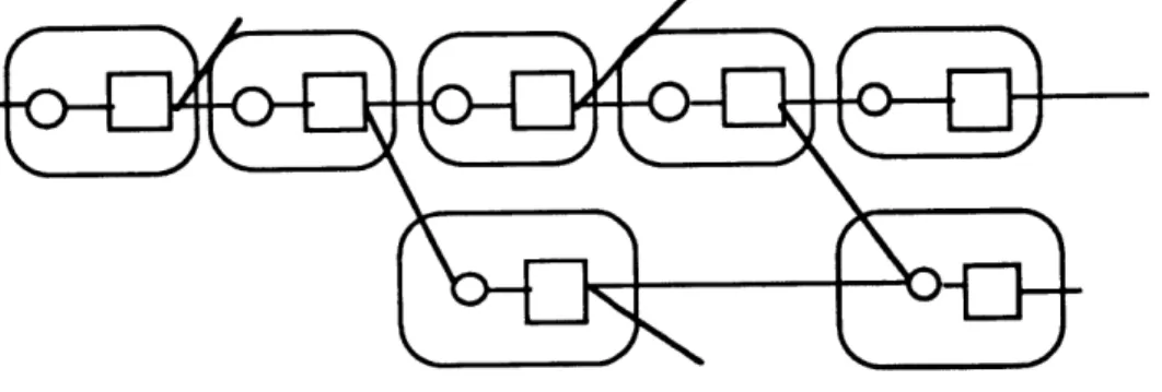
places a g e nts (individuals or organizations), their w o r k(operations to change parts), and the parts manipulated (building parts like windows, pipes, etc) in view together by the use of graphic notation, so that their mutual interactions can be observed and studied. A simple example of a PAct diagram follows:
Agents are represented by the bubbles, parts by the boxes, and operations by the circles. The lines connecting boxes and circles indicate the lineage of parts, read from left to right in the order of precedence. Looking at the elements of the diagrams, agents can be seen in relationship to other agents, parts relating to parts, and parts relating to agents. These are the principle
Control of Parts
12
interactions which PAct diagrams help us identify, account for, and ask questions about.
In the diagram notation, agents A, C, and F have independant bubbles making a pattern of dispersal, while agents B, D and E have nested or overlapping bubbles. From where agent B stands, parts 1 and 2 are parts which are there but which agent B did not have to think about making. On the other hand, agent B makes part 3, one instance of which goes to another agent (e.g. agent F) while also making part 4 because agent D has asked for it. Agent D makes part 6, but has agent E making part 7. Agent E only works upon demand of agent D. Parts 1, 2, 5, and 8 also go to other agents not identified in the diagram.
The agent which makes or changes a part is said to control that part. The agent which asks someone else to make a part has indirect control of that part, while the control of the part rests with the agent actually manipulating or changing the part. The distinction between these two roles is crucial and appears as a thread throughout the thesis. It is important to note that agents do not control other agents; agents control parts. Here, control is a concept with a narrow definition, applying to the relations of agents to parts, not, as it is used in management literature, to refer to human relations or the relations of people to things. (e.g.
Control of Parts
13
1. What PAct Is For and Who May Find It Useful
In the sections which follow, the PAct tool is used to describe a number of value added processes. One set of demonstrations of the use of PAct will be in comparing several ways of building houses. I construct diagrams of principle features of a major post World War II effort to change conventional housing production practice by wholesale introduction of new hardware and agent relations. I refer to the Lustron House initiative. Other diagrams of the value added flows of "conventional" housing technology under a variety of organizational forms will be presented. Discussions about the difficulties faced by Lustron and other cases
will be presented by way of comparisons to conventional
practices. (see §3.2)
Doing this comparative work with the assistance of the graphic notation, we can literally see where in the diagrams of value added flows certain kinds of interactions occur. We know, for example, that Lustron's efforts eventually failed. Looking into the diagram of that initiative, with many agents and parts-making flows under Lustron's roof (literally and figuratively), and comparing patterns we see there with patterns in the other cases which remain alive, we can come closer than before to accounting for the conditions which accompany stability or instability in
Control of Parts
14
housebuilding practices.
For example, a conventionally built house is diagrammed, showing patterns of relations which are apparently congruent with stable and enduring value added flows in the large sense. Discussion about what this means follows, using PAct diagrams to illustrate points (§3.3). The diagrams reveal information flows in various directions between agents, patterns of hardware flows, kinds of agents doing particular work, numbers of steps in making, in whose domain these actions are taken and other important aspects of making processes.
Making a number of diagrams, we can then scan them in successive "diagram sweeps" for particular attributes or characteristics, such as:
* which part (and kind of part) is controlled by which agent, employing which operations (cutting with saws, or lasers; bending by hand or by
special equipment, etc);
* which kind of agents (e.g. expert or layman) appear in which parts of the diagrams;
* which parts of value added flows are characterized by diagrams with many independant agents and which with nested or included agents.
These kinds of questions will be discussed throughout the thesis.
Control of Parts
15
of theory and methodology, definitions and distinctions found by using the tool but usually not found in normal discourse or practice, and comparison of PAct with other models and tools which appear to have similar structures.
PAct has been invented first of all to assist its users in the architectural, construction and manufacturing fields to better understand conventional practice in parts making, that is, what is actually going on in parts manipulation. I have sought to build
a way of giving us more descriptive power of parts making than is currently available. This may put us in a better position for making good explanations of "why" some process, part or control pattern is working well or not, or why some alternative practice or value added flow should be put into use. Comparing alternative practices with the tool is one of its most important methodological contributions.
This is important because a careful reading of the literature on the history of technology, product innovation, and the development of "new building systems" in the building and housing industries shows repeatedly the difficulty of drawing the important lessons from the experiences of others who have explored the same territory before. Books, technical reports and other studies are replete with stories of comprehensive programs such as Operation Breakthrough, General Panel House, Lustron,
Control ot Parts
16
and other less dramatic initiatives, which have failed to bring about the changes envisioned, despite long and costly planning efforts using both private and public funds.
In addition, use of the tool moves us closer to understanding that building "systems" are not invented or designed, but are instead cultivated over relatively long periods of time in the
ground of conventional practice, by the work of many
independant actors. For example, if we admit conventional wood housebuilding practice into the lexicon of "Systems" (notice the designation of this practice in Japan as "the 2x4 system"), then we will be forced to note that no one, no inventor, and no research program produced this "system", but we will also recognize its pervasive influence. If we do recognize this, why then do we hear frequent reference to the introduction of new systems in normal
discourse in building technology?
PAct will also be useful in the discussions about making buildings and parts used in buildings, within those disciplines
whose professional identities depend on the continual
development of new knowledge and insights such discourse offers. Architecture certainly is one such field. While scholarly investigations of the sort engaged in here have not easily found a place among the inquiries in universities bound to the normal divisions of knowledge along classic lines, it is my conviction that
Control of Parts
17
architecture is one of the proper homes of such studies as this one. Architecture, and parts making in the large sense, are endeavors which in practice focus hard on action, but which in study may well seek to understand the parts its practitioners change and the patterns of control in which the parts move.
But, if a place has not been found in traditional university -and architectural - inquiry for this sort of discourse, and if sheer
complexity has made parts making analysis difficult and
inaccessible, apparently these are not the only impediments to precise and accurate descriptions of the kind needed. There is also the issue of how people in the parts making business, including manufacturers, designers, and contractors, craftsmen, regulatory officials, and other practitioners conceive their field of work in intellectual terms: the points of view or "theses" out of which they work.
This question of how the "making enterprise" is conceived is critical especially for those who, for whatever reason, act on the parts repertoire to change it or to alter the practices employed in manipulating parts. The same is true for those who wish to maintain or sustain conventional ways of working or parts flows in the face of changing circumstances.
. In that regard, managers of building product (and project) value added processes need accurate maps to locate possible
Control of Parts
18
impediments and snags to proposed changes in conventional practice; their own, their competitors, or their collaborators. These changes in practice can be in the parts hierarchy (e.g. materials, or materials processing substitutions, changes in assembly sequence, location, etc.) or the deployment of agents (e.g. backward integration, vertical integration, out-sourcing, buying stock, improved supplier/user links, etc.), or, as is usually the case, both agents and parts as they interact.
Because PAct introduces control in parts making via a graphic notation tool, these questions of practice are now more accessible to mapping and analysis by ordinary visual means, and, in the future, with computer support (see §4.6). Simple and varied examples of such mapping and comparisons are given throughout the thesis as illustrations of what will in time become more sophisticated and thorough analyses.
PAct is also designed with historians of technology in mind. Scholars who study artifact production need accurate descriptions of many value added flows, for the purposes of comparison and analysis. Processing and comparing many diagrams will enable researchers to study patterns of parts flows among complex agent domains with the result that specific kinds of interactions will be easier to spot and study, and meanings of such interactions imputed. PAct can also be of value to the new field of
Control of Parts
19
sociotechnology (Bijker, 1987), which redraws intellectual
boundaries in the social sciences by demanding a serious study of the social construction of technological systems.
PAct has been built so far with these constituencies in mind, and with the idea that those who wish to innovate should know what it is they work to change: the control of parts. While the questions that motivated the study at the outset were and remain interesting (see §5.1), building and demonstrating the tool has been the objective of the research. The tool is now available in its rudimentary form for exploring an array of questions beyond those which informed its invention in the first place, and more
accurately than we can by normal discourse.
Studying parts making this way, we can learn what to leave alone, and what may be changed in light of the control people exercise.
Control of Parts
20
2 Parts Making up PAct Diagrams
PAct diagrams are made up of graphic symbols organized in particular ways. Each symbol and relationship between them is assigned a specific meaning. The main elements are
Parts
Operations Parts liasons Agents
These four basic elements of the diagrams will be described in detail in this section by use in simple examples in which relations between these symbols will also be described.
Traditions of diagramming are recognized in the construction of PAct (see also §4.5). (Martin and McClure, 1985)
2. 1 Parts
Parts include such things as fasteners, boards, hinges, windows, walls, houses or any other part or grouping of parts that is named, regardless of its complexity. A part can be shown as such whether it is understood to be composed of many other
Control of Parts
21
parts (e.g. a window or tenant improvement package) or
understood as having no individual parts we want to identify (e.g. a pipe).
I limit the kind of parts used in the diagrams which follow to those parts which are normally found in a building materials supply depot, parts supply center, manufacturing plant, or prefabrication shop; generally, parts we can pick up and hold or which are normally manipulated by machines or equipment in building construction work.
A part is displayed in PAct diagrams and in the following text by the use of the symbol
0 diagram #2.1
Every part is assigned a name or identity code, for example a "casement window", part "#45B", "[parts 3 + 4]", "Honeywell Heat
Pump model #4452N", or whatever coding convention or
designation is desired. D 17 is one way to signify the number of instances of a part.
Control of Parts
22
L
Operations
Parts change as they make their way along a value added chain. This is the definition of value added used here: physically changing a part. Values, including costs, can certainly be assigned to these physical changes, but such values are different from, though not unrelated to, such physical manipulations as the tool accounts for.
These changes are the result of operations of one kind or another, or some combination of operations. In PAct diagrams and in the text , an operation is shown by the symbol
0 diagram#2.2
There are four principle kinds of operations:
assembv
in which several parts are brought together into a new part; for example, a window sash is brought together with a window frame, or veneers are laminated to make a piece of Microlam engineered lumber, or a wall is brought into place on a platform. Of -course, there are many kinds of assemblies. Four are of particular note in terms of the relation of their parts: parts are 1)
Control of Parts
23
fixed but removable, 2) fixed but not removable without destruction of the parts, 3) adjacent and removable, and 4) adjacent but removable only by disturbing one of the associated parts.
removal:
a part is taken away, or material removed; e.g. holes are drilled in joists for wiring and piping runs; or a piece of sheet plastic is cut into pieces each of which has a planned use producing no waste;
disassemblv:
this operation is one in which a part is detached from another part in a reversal of a prior assembly operation; for example, the door in a prehung door unit is removed after the unit is installed in the wall, for ease of painting; disassembly occurs as a reversal of an earlier assembly process, but not always in the same order. That is, an object with an assembly process involving four parts may be disassembled into two parts.
deformation:
in which the form of a part is changed without adding or removing anything; for example, a copper pipe is bent; or a gasket is compressed into a slot. (casting a material such as concrete is here classed as a kind of deformation; first, the aggregate, sand, and cement are assembled; then cast into a form,
Control of Parts
24
without adding or removing anything; here are two operations). These operations can be complex, employing a number of secondary operations and procedures. For example, assembly may require certain clamps, jigs, alignments, and rotations. Studies in product manufacturing discuss these procedures (e.g. Andreasen, 1983; Hounshell, 1984).
In the PAct diagrams in this study, I limit the operations diagrammed to those which alter a part in a visible way. There are many important changes to parts which are invisible to the naked eye and which add value, such as the work General Electric does in developing a new plastic resin, or Weyerhaeuser's development of a new hybrid tree that exhibits improved growth
and fiber strength characteristics. These changes can also be mapped using PAct principles, if we consider cells, molecules and other microcellular elements as parts, but examples of this sort are not in this study. It would be interesting, for example, to use PAct to diagram "designer genes", or other projects in microcellular developmental biology.
An operation is generally not "tool" specific in the long run, in the same way that a design method is not tool specific. A given tool can be found in more than one method, and a method can employ various tools. Someone always seems to be inventing another way to do an operation, not at random, but accompanying
Control of Parts
25
other activities in parts making. An operation of assembly can utilize an assortment of tools or devices, depending on the way an agent wants to or knows how to work, or in some cases by specification from another agent ordering the part. Substituting tools often accompanies other shifts in social relations, economics, new materials, in making the same kind of things. Historical studies of mass production in American woodworking industries
show this. (Hounshell, 1984)
But particular tools can also remain a constant while other conditions change. For example, Japanese carpenters still employ tools with ancient lineages, in projects whose designs and off-site production are accomplished with sophisticated computer assistance. Or, an operation of removal can use an assortment of devices. Cutting can be done by saws, knives, tearing, or lasers, but the operation is still classed as a removal operation. Sometimes, operations of a kind become so frequent that the part being changed experiences a basic alteration, eliminating the operations. For example, floor framing in houses was almost always of 2x10's or 2x12's, normal "made for stock" dimension lumber. Now, a widely observed convention is the use of open web wood floor trusses, always "made to order", of the same or even greater nominal height dimensions. With the new part, no holes have to be cut, through which to run pipes, ducts, wires,
Control of Parts
26
sprinkler lines, now required in many wooden house projects. So
many holes were being required in the solid 2x12's to
accommodate the tremendous increase in resource distribution lines, or the reduction of ceiling height by routing these subsystems below the joists, that eventually it became easier to have special deeper trusses made, higher on the value added chain and designed for each house, and no longer stock items like
2x12's.
The PAct diagrams focus on actual changes to parts. Therefore, the 0 symbol will not be used to identify such actions as selling, buying, transportation or warehousing. Such influences on the control of parts may be accounted for in other tools.
2.3 Parts Liasons
Parts in the built environments we make and change - the kind studied here - have histories and futures. Even parts found in museum displays are only temporarily denied a future of the sort this tool maps. The parts accounted for in PAct exist somewhere in a continuum starting with a substance in nature, returning in time to some basic substance. To show a part of this
Control of Parts
27
diagram #2.3
to represent parts liasons. Parts exist in part/whole hierarchies in value added chains; the lines of parts liasons are those which can be followed to find out where a part goes and where it comes from in a value added flow; what it is made of and what it will become part of.
2..A
Agents
Agents in PAct diagrams are those who change parts, or act to cause another agent to change a part. "Agents" is a general term, to be specified as needed in each diagram. An agent can be an individual, a group, a company, a division of a company, or any other actor who engages in a value added flow. An agent is shown in the diagrams by
Control of Parts
28
The shape surrounds a domain of action with which an agent is identified. In the text discussion of diagrams, agents will be designated both by the word "agent" and by the symbol @.
Agents in PAct diagrams who manipulate parts perform "work", as contractors think of it, as distinguished from providing a "service" such as designing. This is also the language in normal professional contracts in construction practice. The general term used for this work is control. An agent who changes a part
controls that part.
Control = physical change of a part by a human agent.
Only one agent can control a part at one time. For example, a single craftsman, using a routing tool, shapes a wooden piece for use in a window frame. Or, a team of two workers tilts a stud wall into place. Here, the "agent" is understood to be the collective of both workers acting together on the "part" called a stud wall frame. Or, a company makes doors. The collective of workers actually doing the work constitutes the agent in this case, and the parts are doors. Of course, we can look into the company and find many agents. How many agents we see in the PAct diagrams we make depends on the detail we want to examine.
Control of Parts
29
2L.5 Simple PAct Diagrams as Illustrations
Summarizing, PAct diagrams include representations of:
* Parts, in part/whole hierarchies, linked by liason lines;
* Between parts are operations, indicating the change that occurs to make the new part in the value chain;
* and agents, those who control or physically change the part.
2.5.1. Parts and
Operations
The following series gives some basic arrangements of the elements of PAct diagrams.
1 3 4 diagram #2.5
2
lI1 and l 2 are assembled to make E13, which is then subject to an operation of deformation to make E14. An example might be the assembly of a flexible gas pipe used to hook up a gas appliance to the house gas line. The pipe is assembled with its coupling parts, then bent to fit the specific requirements of the
Control of Parts
30
appliance's installation. The lines are the liasons between parts; the O's are operations.
This diagram, like all PAct diagrams, is read by following the liason lines linking parts in part/whole hierarchies. Reading right to left, we see a part's history; left to right we see its future.
In a value added flow, we will call "upstream" parts those whose liason lines attach to an operation to the left of a hidden vertical line through it (see diagram below). This means looking in the direction of sources. We will call "downstream" parts those that are found by looking in the direction of use, or whose liason lines attache to an operation to the right of a hidden vertical line through the operation (see below).
I
operation
diagram#2.6
upstream downstream
The relation of parts in a specific value added chain can be topologically constant but variable in arrangement. Liason lines in a specific chain can remain attached to their parts and operations in specific places. Any given diagram is free to be arranged in any pattern, however. For example, if scheduling is of interest,
Control of Parts
31
"stages" can be organized (see e.g. diagram #3.29, and #4.25). If the entry of a part into a chain is to be moved, the point of attachment can be altered without changing the upstream or downstream portions of the diagram. For example, if a house is assembled off-site, and brought onto the foundation late in the value added chain, that is one situation (see §3.2.4). We can alter the place in the diagram at which the house is brought together with the foundation, by changing only that part of the diagram effected by that shift. This may impose other changes to the value chain, producing still another diagram.
So far, operations of assembly and deformation have been shown. An operation of disassembly is shown next:
6
15 7
3
2 4 diagram #2.7
In this diagram, parts are assembled, and also a part is disassembled, and then assembled with another part. An example is a Pella window. El1 represents the glass parts, E12 the wooden sash assembly. The glass is installed in the sash to make 113. The next operation shows that this assembly is disassembled (we
Control of Parts
32
know it is only partly disassembled, but the details do not show up here), and F16 (the slim-line shade that fits between the double glazing panel) is installed with 14 and 05, to make the finished unit. 114 and 1 5 are different than parts E11 and 0 2.
It may be that a part will not be disassembled into the same parts from which it was assembled in a prior stage.
To summarize so far, in a value added chain we start with an operation making a part, and end with a part and a liason line leading to a future state. To the left of a part there is an operation, and to its left a line indicating some lineage. Operations are either assembly, disassembly, removal, deformation or some combination.
PAct diagrams are read from left to right, from making to using; from upstream to downstream; from "lower value added" to "higher value added".
In order to handle the complexity of value added chains, PAct diagrams use the principles of abstraction and specification. This means that a complex chain of parts and operations can be represented compactly without loosing information, but can be "opened" to find out more. For example, the chain making a Pella
window, composed of over 150 discrete parts and their
Control of Parts
33
diagram #2.8
in which all operations are "in" the one 0 symbol, and all parts are "in" the single 11 symbol. (A reason to distinguish between 0 and D is discussed, for example, in §3.1). This is particulary useful when we want to show a Pella window in a downstream chain, but are not interested to display all that makes up the window, as in
window
1 window in wall
3 2
wall
where a window and a wall come together to make a new assembly.
If we then choose to find out more about what makes the window, or the wall, or if we wish to find out more about what operations are "in" the 0 symbol, we then "open" the part or operation.
Control of Parts
34
window
window in wall
diagram #2.10
In this way, we can manage the complexity of value added chains according to the need to display elements of the parts making. This also suggests the need for data sets 'held' by a computer for specifying any part of a PAct diagram. (see §4.6)
When we open a E symbol and/or an 0 symbol, we follow certain diagramming rules as indicated here:
Control of Parts 35
where opening an 0 we see a new string of 0 and E but always beginning and ending in an 0; and where we open a E, we see a new string always beginning and ending with a E.
2.5.2 Agents
We now bring in agents. An agent (©) controls (changes) a part:
A diagram #2.12
This is the most simple designation of control. @A controls FI11. An operation is involved. For example, @A bends a wire the result of which is E 1. The part has come from some upstream source and is going to some downstream use. The agent in whose bubble 01 occurs is the agent controlling the next downstream part, in this case n 1.
When several agents are in view in one diagram, we can see a situation such as this one, characterized as a "dispersed" pattern:
Control of Parts
36
1 2
A B
diagram #2.13
where two agents each control a part. @A controls l 1, and @B controls E02. These agents control independently. @B uses 0 1 to
make l 2. For example, Pella is @B, controlling l 2, and Acme Screw Company, @A, controls l1, wood screws. This diagram shows that Pella uses wood screws, but that Pella controls the use of, not the making of the wood screws.
More than one @ can also appear in a diagram in another way, characterized as a "nested" pattern:
B diagram #2.14
in which @A controls EL 1, @B controls E12, but where @B has what I shall call indirect control of EL 1. The diagram shows that the agents are interdependent by virtue of the postions the bubbles take relative to each other: they overlap. @B needs to have Li 1 in order to make L2, and gets it by exercising indirect control. In
Control of Parts
37
this diagram, @B specifies lI1 and @A controls it. @B is in need of @A's work contribution.
For example, if ©B is Pella, and @A is its sash production group, Pella gives a specification to its sash group, which controls the various parts making a sash. The sash then finds itself put into a Pella window. This diagram abstracts many complex operations in a simple diagram for the purpose of showing another way agents can be shown in PAct diagrams.
Another way @'s appear is:
1
diagram#2.15
in which the sash group controls 13 by assembling it from 02 and Eli. 12 (rubber gasketing) comes from a third independant @C which controls E12, outside Pella. It is not specified by Pella. @B (Pella) controls E11, which is an assembly of three parts coming from the upstream side, and 14 which is the finished window. @B has indirect control of 13, and @A controls 13.
Control of Parts
38
A more accurate diagram of this situation would show E112 also going to another agent, which means that 02 is a "made for stock" or commodity part:
B A
3 4
1" diagram#2.16
Agents also relate in the way shown here:
Control of Parts
39
in which @A controls El and E2, @B controls 13, and @C controls 04. Here, @B has indirect of control of E12. For example, Pella (@B) and Pittsburg Plate Glass (@A) and Silver Spring Glass Company (@C), relate in this way. Pella specifies (indirectly controls) E2, and PPG controls it. This actually happens. Pella orders a certain quantity of glass of a certain kind cut to specified sizes, and as the glass comes off PPG's float line, this quantity is cut and sent out to Pella.
Silver Spring Glass Company, on the other hand, does not have indirect control of any glass in PPG's control, but takes glass as it comes. Silver Spring Glass Company then controls glass for subsequent chains, but characteristically only on order from agent D, which assembles E4 with another 15 to make E16.
I have now laid out the basic diagramming technique, identified the basic relations that PAct diagrams reveal, and have indicated how complex value added chains can be closed (abstracted) or opened up (specified) to see more.
Control of Parts
40
0
-Demonstrating PAct Use
I now show how PAct diagrams can be organized in more complete ways. First, I show diagrams of a specific part of moderate complexity: an ordinary Pella (aluminum) Clad window made by the Rollscreen Company. These diagrams enable me to specify a number of terms introduced earlier. These include such concepts as control and indirect control, and terms such as prefabricated, industrialized, mass produced, stock or commodity products, made to order parts, vertical integration, and others.
Then, I compare four different value added chains, including both conventional and "unconventional" approaches to building houses. This enables me to go further in discussing and analysing patterns of interactions between parts and between agents, and
between parts and agents, newly revealed in PAct diagrams.
Part of what comes from the exercises of comparing four different house production processes is a new way to describe conventional practice in making houses, and by extension, other artifacts. The view we get from "reading" the diagrams engages both the organizational and the technical sides of housebuilding, which helps us to pin down the conditions in the interactions of people and things which accompany stable yet evolving technical
Control of Parts
41
LJ
PAct Diagrams of a WindowThis section shows how a series of PAct diagrams can be made of a specific window's value added flow. The diagrams are abstractions of complex processes involving many thousands of agents and many hundreds of parts, spread over a very large part of the globe. These are subject to a large (and changing) number of influences, including design, cost, regulations, transportation and so on.
First, an overall picture of the "basic" complete unit, showing 10 parts:
FIXED UNITS
510
Control of Parts 42
I begin with a highly abstract diagram, then give other diagrams that open up to show what actually happens in making the window.
all operations
supply -- use
diagram #3.2
where the entire work of making the window is compressed into the single part box and all operations into the single operations box. Supply is to the left, and use to the right. The only agent shown is "Pella."
The next thing I show is more detail on the supply side. This means that parts controlled (again, physically changed) by suppliers will show up in the diagram.
For simplicity, I will show suppliers according to the materials they control: wood, metal (e.g. found in parts #1, 2, 3, 5, 6, 7, 8, in diagram #3.1 above), , glass (one element of part #6 in diagram
#3.1 above) and synthetics (e.g part #4 in diagram #3.1 above). The following diagram shows these:
Control of Parts
43
diagram#3.3
where there are also four new agents, each associated with a kind of part supplied to Pella for its use. The above diagram indicates that each of the agents supplying Pella is independent, and controls parts. The stub lines coming out of each of these independent domains tells that these parts also go to other (unidentified) downstream agents other than Pella.
A more accurate view of the "supply" or upstream side related to Pella is the following:
Control of Parts
44
where we see that Pella is bringing in parts of the same material from more than one supplier. El1 and D2 are interchangable from Pella's point of view. This may happen when a user does not want to become dependent on only one supplier. For example, Pella may obtain kiln dried cabinet grade white pine from several producers for use in making the window frame and operable sash of the window we saw above (wood parts in parts #1, 2, 3, 5, and parts # 7, 9, and 10).
This means that @A and @B control parts suited to Pella's use; the producers act for their own reasons. An interesting question is whether Pella's operations are identical when accommodating the incoming supplies from more than one supplier of the same parts. It seems that a condition for having more than one supplier of a part is that operations under the control of the user must not be different because of the multi-agent stream of supplied parts. For example, one supplier may offer straight grain stock, while another may offer finger-jointed stock. They are interchangable parts from Pella's place in the value added flow, because Pella will paint the product so the finger joints will not show, but from the producer's side, they each have their special production stream.
In addition we can see a situation as in the following pair of diagrams:
Control of Parts
45
@ A wood part
diagram#3.5
where one @A controls both wood parts E11 and E12, but 12 is indirectly controlled by Pella. The Pella domain indicator includes E32 (but notice it does not include the operation making it). Note: the way to know which agent controls in situations of domain overlap is to determine to which side of the diagram (left or right) that agent is connected. Here, @A controls E12, while Pella controls D3window.
An example of this situation occurs when Pella is supplied with two shapes of wood which both find themselves in our window: E11 which is 'standard' size, and 2 which Pella specifies, both from @A.
Meanwhile, 11 1, controlled by @A also goes to another unspecified agent. This is indicated by the stub line.
The next diagram is similar to the last one:
-Control of Parts
46
@ A wood pr
diagram #3.6
except that here, both the operation making II 2 and ii 2 are indirectly controlled by Pella, and controlled by ©A. This indicates that Pella specifies not only D2 but how it should be controlled. This would occur when certain characteristics of 12 could only be achieved, from the point of view of Pella, by using a particular process or tool. The previous diagram (#3.5) indicated that only 112 was specified by Pella, meaning that Pella agreed to have ©A use whatever kind of operation it chooses among all possible tools, processes,
jigs,
location, and so on, as long as 112 is the result as specified.©A is, however, an unlikely kind of agent as diagrammed. One agent would be hard pressed to do what is shown, since each kind of control is connected to different kinds of downstream activities and information flows. A more likely situation would be one diagrammed here
Control of Parts 47 M window parts @A ... ... ... ... ... ... ... ... ... .... . ... .... . .... ... .. ... ... X :,fi-on.d.0""': ... ... .. ... ...T ... ... ... . 2 -:.*.'.'.'.'.'.'.'.'. ... ... ... .A .... ... ...... ... ..... -.. ......... ...... ... ... ... ... . ...... ... ... ... ... .. ...... ... ... ... ... diagram #3.7
where 1 and E12 are associated with distinct and independent @A and ©B. Or, @A and @B can be agents within a larger organization ©C as shown here:
diagram#3.8 A variation on diagram 3.7,
controlling 01 and E12 would be:
with independent agents
Control of Parts
48
where @B also serves other downstream users by making more than one part, with more than one user. 0 4 and El 5 go to other agents.
On the other hand, if an @B makes only one part, that agent can more commonly appear in a diagram like this:
diagram#3.10
in which @B is now a division of Pella, and not an independant entity.
In the following diagram, which appears to be just like diagram #3.10, we see an @B making only one kind of part, supplying both Pella's 13 and also unidentified agents and parts flows indicated by the stub line.
Control of Parts 49
@A
Pella
diagram#3. 11
This situation, however, may be unusual in practice. I do know of a division of a large Dutch construction company which is interested in making parts of a kind both for its own projects and for trade. If they are considering this, it must be a practice with precedents. However, there is also the logic that this practice would put a supplier into competition with its market, a situation which is apparently not advisable in certain circumstances.
This is an example of an important use of PAct diagrams: to map a situation which works in the logic of the diagramming but may not work, or work often, in reality, or may only occur in practice under certain very specific conditions. That is to say, by following a line of "diagram thinking" that makes sense in its own right we make patterns which, if we ask what they may represent in reality, can cause us to look with fresh insight on practices we take for granted or have never thought about. Making PAct patterns in this way, as in exploratory sketching during the
Control of Parts 50
designing of a building, can lead to new ideas that may not have emerged at all, or in the same way without visualization.
If we now move into Pella's territory itself more fully and open up E3, other parts, operations and agents come into view. In fact, exactly the same kinds of diagram forms will appear, but with more complexity when we keep widening the net of supply and use sides of the diagram.
If we open the use side of the diagram, we will see exactly the same kinds of diagram forms as we have seen on the supply side. For example, a user of Pella windows may relate to Pella in one of two ways, or both:
diagram#3.12
where ©C takes D 3 (a standard window also available to any other downstream agent), and ©D has indirect control of E14, which Pella controls. E14 is, for example, a custom shape unit using the same parts that go into a "stock" shape unit.
Control of Parts 51
In some circumstances, Pella may in time decide to operate in a way described in this diagram:
diagram#3. 13
in which Pella may find it useful to supply D 4 to other downstream agents such as ©E. If agent D were to protest by declaring copyright infringement, would it have a basis, since Pella controls the part? Had ©D wished to claim a patent on L14 (e.g a special window), could it restrict Pella from supplying the D4 window to ©E? In order for Pella to supply both ©D and ©E, does ©D have to withdraw its indirect control of 114?
This concludes the basic examination of a value added chain using PAct. Additional questions will be addressed in the next section when comparing different chains for making houses in four different ways.
Control of Parts
52
LZ
Comparing Four Value Added ChainsBy comparing a number of PAct diagrams, the patterns of relations between parts, and between agents can be examined. Some of that has been done above with the sample window. More examples follow here, and additional comparisons will be given in §4.3.
One of the more interesting and important controversies in the disciplines engaged in technical innovation has to do with the role of convention as either an impediment to or as a basis for improvements in technical practice or the technical parts we use. Should we "break from tradition" or "build upon what is there"?
A controversy couched in such either-or terms may from the beginning be of diminishing interest since a practical view would suggest that improvements must have to do with both in some pattern of intricate interplay. (e.g. Weisberg's, 1986; G. Daniels,
1970).
We can look into this controversy with added clarity by comparing PAct diagrams. An examination of the patterns in many PAct diagrams give us a basis for inferring what it is that makes conventional practice in complex parts making enterprises persist, or what about conventional practice makes it a good basis for innovation. The other competing perspective which has been
Control of Parts
53
in currency - that convention is a major drag on innovation - can
also be examined. We can begin to see more exactly what conditions in value added chains accompany the stagnation of hardware and software.
PAct diagrams help advocates of each of these viewpoints see what their positions mean in a larger context, but the very act of making successive diagrams to represent value chain states argues for convention as the basis of innovation. What is of interest is to discern exactly what conditions preceed and follow change of a part or process or agents relations. PAct is tooled to help us with this.
The examples I use next for the purposes of comparison and lesson drawing, like the window demonstration in the last section, also come from the housing industry. I show three variations of a kind of house production practice using conventional wooden housebuilding technology.
First, I diagram a "conventional wooden" house, built on site, first as a house built speculatively for sale, second as a house built to order. This way of building, which should be called the 2x4 system, is used throughout North America for most of the normal residential developments of detached and low rise
construction.
Control of Parts 54
prefabricator, most parts for which are prepared in an off-site plant leaving significantly fewer operations for direct site work than the "site built" example. Acorn Structures houses nonetheless fall within the technical vernacular of the site built house: the parts supplied to Acorn and the operations performed are in the main identical to that of the site built house. Acorn works only on the basis of orders from customers. It does not make house packages speculatively.
A third, contrasting example is from a house differing in many ways from what was at the time and still is conventional practice. This is the Lustron House, conceived in1946 by Mr. C.G.
Strandlund, then executive Enamel Product Company.
government allocations of enameled gasoline stations. a steel house came about "mass produced housing".
Fourth, I diagram a
Industries, also fully
housebuilding technology.
vice president of the Chicago Vitreous At that time, Strandlund sought federal steel for use in constructing vitreous The Lustron house, largely known as in the post WWII enthusiasm about
house module produced by Cardinal
within the conventional wooden
Cardinal's production division only produced modules on order, but as it turns out orders which only came from other divisions of Cardinal.