Discovering the patterns of human-environment
interactions using scalable functional textiles
by
Yiyue Luo
B.S., University of Illinois Urbana-Champaign (2017)
Submitted to the Department of Electrical Engineering and Computer
Science
in partial fulfillment of the requirements for the degree of
Master of Science in Electrical Engineering
at the
MASSACHUSETTS INSTITUTE OF TECHNOLOGY
May 2020
c
○ Massachusetts Institute of Technology 2020. All rights reserved.
Author . . . .
Department of Electrical Engineering and Computer Science
May 15, 2020
Certified by . . . .
Wojciech Matusik
Professor of Electrical Engineering and Computer Science
Thesis Supervisor
Certified by . . . .
Tomas Palacios
Professor of Electrical Engineering and Computer Science
Thesis Supervisor
Accepted by . . . .
Leslie A. Kolodziejski
Professor of Electrical Engineering and Computer Science
Chair, Department Committee on Graduate Students
Discovering the patterns of human-environment interactions
using scalable functional textiles
by
Yiyue Luo
Submitted to the Department of Electrical Engineering and Computer Science on May 15, 2020, in partial fulfillment of the
requirements for the degree of Master of Science in Electrical Engineering
Abstract
Humans perform complex tasks in the real world thanks to rich and constant tactile perceptual input. Being able to record such tactile data would allow scientists from various disciplines to study human activities more fundamentally and quantitatively. Moreover, capturing large and diverse datasets on human-environment interactions and coupling them with machine learning models would allow the development of future intelligent robotic systems that mimic human behavior. Here, we present a textile-based tactile learning platform that enables researchers to record, monitor, and learn human activities and the associated interactions. Realized with inexpensive piezoresistive fibers (0.2 USD/m) and automated machine knitting, our functional textiles offer dense coverage (> 1000 sensors) over large complex surfaces (> 2000 cm2). Further, we leverage machine learning for sensing correction, ensuring that our
system is robust against potential variations from individual receptors. To validate the capability of our sensor, we capture diverse human-environment interactions (> 1,000,000 tactile frames). We demonstrate that machine learning techniques can be used with our data to classify human activities, predict whole-body poses, and discover novel motion signatures. This work opens up new possibilities in wearable electronics, healthcare, manufacturing, and robotics.
Thesis Supervisor: Wojciech Matusik
Title: Professor of Electrical Engineering and Computer Science
Thesis Supervisor: Tomas Palacios
Acknowledgments
I am very thankful to my advisors Professor Wojciech Matusik and Professor Tomas Palacios for their guidance during the course of my Master’s thesis.
I would also like to thank my collaborators Yunzhu Li, Wan Shou, Pratyusha Sharma, Kui Wu, Michael Foshey, Beichen Li for their guidance, support and help throughout the project.
I would like to thank my labmates Alexendra Kaspar and Liane Makatura for training and guidance on digital knitting machine. Great thanks to Petr Kellnhofer and Subra Sundaram for their helpful suggestions to this work.
Last but not least, I am grateful to my family and friends for their support in all possible perspectives.
Contents
1 Introduction 15
2 Background and Related Works 17
2.1 Tactile Sensing . . . 17
2.2 Smart Textile . . . 18
2.3 Digital Machine Knitting . . . 19
3 Method 21 3.1 Coaxial Piezoresistive Fiber . . . 21
3.2 Digital Machine Knitting . . . 22
3.2.1 Inlay . . . 23
3.2.2 Designs of Full-sized Sensing Wearables . . . 26
3.3 Data Collection . . . 28
3.4 Computational pipelines . . . 29
3.4.1 Sensing Correction . . . 29
3.4.2 Classification . . . 30
3.4.3 Pose Prediction . . . 32
4 Experimental and Learning Results 35 4.1 Fiber characterization . . . 35
4.1.1 Morphological Characterization . . . 35
4.1.2 Electrical Measurement . . . 36
4.2 Full-sized Sensing Wearables . . . 38
4.3 Self-supervised sensing correction . . . 40
4.4 Applications . . . 42
4.4.1 Object Classification . . . 42
4.4.2 Action Classification . . . 43
4.4.3 Interaction Classification . . . 44
4.4.4 Pose Prediction . . . 47
4.4.5 Robotic Manipulation and Control . . . 48
5 Summary and Future Work 49 5.1 Summary . . . 49
5.2 Future work . . . 49
A Tables 53
List of Figures
2-1 A. An optical-based tactile sensor, Gelsight [19] B. Biomimetic elec-tronic skin [7] C. Tactile glove for human grasping signature learning [41] . . . 18
2-2 A. Capacitive sensor array is incorporated into garments through weav-ing of customized copper thread. Gesture recognition is performed to demonstrate human-computer interaction [29]. B. Large scale resistive sensors are integrated through knitting of conductive yarn[28]. C. En-ergy harvesting and storage are performed by the direct printing of smart patterns on textile[53]. D. Body movements are captured by smart clothing with conductive traces for applications in games and virtual reality(VR). [1]. . . 19
2-3 A. An Industrial double-bed weft knitting machine, Stoll CMS 730K [39] B. An industrial machine knitting design system, SDS-ONE APEX [36] C. 3D knitted full garments designed by a customized compiler for automatic machine instruction conversion [24]. . . 20
3-1 A. Coaxial piezoresistive fiber fabrication set-up. B. The effect of ap-plied pressure and pulling speed on the thickness of fabricated piezore-sistive fiber. . . 21
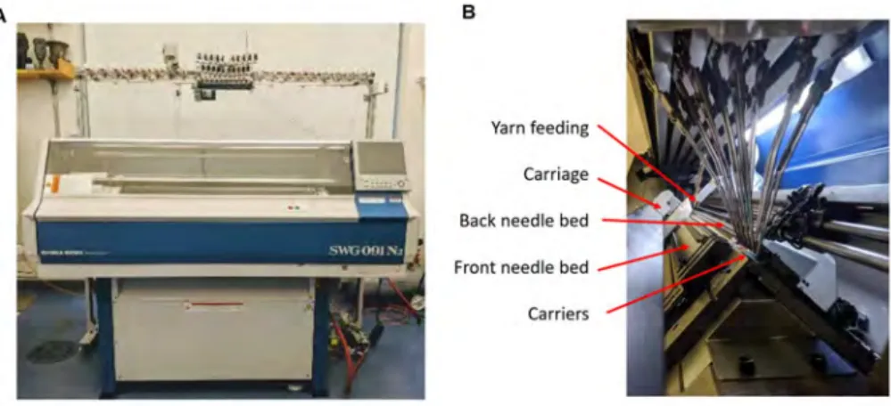
3-2 A. Industrial knitting machine, Shima Seiki SWG091N2and B. its main
3-3 Illustration of A. important components of commercial digital knit-ting machine (SWG091N2) and operations of B. knit, C. tuck and D. transfer. . . 24 3-4 Illustration of A. automatic inlay and B. manual inlay . . . 25 3-5 Design of full-size A. glove, B. sock, C. vest and D. KUKA sleeve
embedded with tactile sensing matrix. . . 27 3-6 A. A modified electrical-grounding-based isolation circuit architecture
for passive sensing array readout. B. the designed PCB board c. The response of a single sensor in response to applied load at the output of ADC. . . 28 3-7 A. Procedure for correcting the tactile glove and B. the tactile vest. 29 3-8 Models for A. sensing correction, B. classification, and C. full-body
pose prediction. . . 31
4-1 A. Photograph of coaxial piezoresistive fiber (> 100 m) and sensing fabrics. B. Morphology of coaxial piezoresistive fiber under microscope and SEM. . . 35 4-2 The resistance changes of a single sensor (composed of two
piezoresis-tive fibers) A. in response to applied normal force and B. during load and unload cycle test (over 1000 repetitions). C. Effect of functional fiber thickness on sensing unit performance. D. Resistance change of an unloaded sensor treated with various temperatures. . . 36 4-3 Resistance profile of a single sensor composed of coaxial piezoresistive
fibers fabricated with A. various copper concentration and B. various graphite concentration . . . 37 4-4 Stress-strain curve of fabricated coaxial piezoresistive fiber and normal
knitting yarns from tensile testing. . . 38 4-5 A. Example of a double-layer fabric structure. B. The influence of
fabric structures (manual inlay and automatic inlay) on device perfor-mance. . . 39
4-6 Automated manufactured full-size tactile A. glove, B. sock, C. vest and D. robot arm sleeve. . . 39 4-7 A. 15 positions on tactile glove, B. correlation between the tactile
read-ing and the scale’s readread-ing increases. The correlation between the sen-sory response and references increases for C. the glove, D. the right sock, E. the left sock, F. the vest, and G. the robot arm sleeve. . . 40 4-8 Self-supervised correction results on the tactile A. glove, B. vest, C.
sock, and D. robot arm sleeve. . . 41 4-9 A. 26 object classes and B. the confusion matrix from classification. . 42 4-10 A. We collect tactile information from a vest with a sensing matrix at
the back while the wearer sits, lays, and leans in versatile poses. B. Confusion matrix from poses classification with an accuracy of 99.66%. 43 4-11 PCA on tactile maps from walking (insets are corresponding tactile
frames). . . 44 4-12 A. Pressure imprints from different sitting postures and B. tapping
with potential application in human-computer interactions. . . 45 4-13 A. Photographs of 10 different poses. B. The confusion matrix for
classification and C. T-SNE plot from our pose dataset recorded by the tactile vest. . . 46 4-14 A. Example photographs and tactile frames of “M”, “I” and “T” pressed
on the tactile vest and B. the confusion matrix for classifying the letter and the orientation. Accuracy drops as sensor resolution decreases. . 46 4-15 A. Location of the 19 joint angles representing body pose in our model.
B. MSE in pose prediction. Influence of C. sensor resolution and D. number of input frames (temporal window) on prediction performance. The dashed line represents the baseline defined as the canonical mean pose of the training data. E. Comparison of various poses recorded by MOCAP (ground truth) and the same poses recovered by our model from the tactile socks pressure frames. Notable errors in the arm region are highlighted in red. . . 47
4-16 Tactile feedback from physical interactions with robotic (KUKA) arm with potential applications in robot manipulation and control. . . 48
B-1 Examples of self-supervised corrected results of tactile A. glove, B. sock, C. vest, and D. robotic arm sleeve. . . 56 B-2 The human pose is represented by 19 joint angles in axis-angle
repre-sentation of three dimensions (illustrated as 3 components). . . 57 B-3 Retrieved tactile frames from socks embedded with sensing matrix,
ground truth motion from motion caption system (XSens), and corre-sponding motion prediction for A. lounging, B. squatting, C. twisting, and D. waist-turning. . . 58
List of Tables
A.1 Cost estimation for coaxial piezoresistive fiber fabrication. . . 53 A.2 Cost estimation for full-sized sensing wearables manufacturing. . . 54
Chapter 1
Introduction
Living organisms extract information and learn from the surroundings through con-stant physical interactions [12]. For example, humans are particularly receptive to tactile cues (on hands, limbs, and torso), which enable the performing of complex tasks like dexterous grasp and locomotion [10]. Observing and modeling interactions between humans and the physical world are fundamental for the study of human behavior [47, 35, 20], healthcare [37], robotics [51, 50, 22, 26], and human-computer interactions [29, 34, 18]. However, many studies of human-environment interactions rely on more easily-observable visual or audible datasets [25], because it is challenging to obtain tactile data in a scalable manner. Recently, Sundaram et al. [41]coupled tactile-sensing gloves and machine learning to uncover signatures of human grasp . However, the recording and analysis of whole-body interactions remain elusive, as this would require large-scale wearable sensors with low cost, dense coverage, conformal fit, and minimal presence, to permit natural human activities.
Although wearable electronics have significantly benefited from innovations in advanced materials [52, 49, 31], designs [32, 16, 45], and manufacturing techniques [3, 43, 28], there are no existing sensory interfaces that would suit the needs described above. However, the automated manufacture of such smart wearable sensors in the form of whole-body garments, and their ensuing tactile data collections, would benefit many fields. The garments could equip humanoid robots with electronic skin for physical human-robot collaboration [50, 10], or serve as auxiliary training devices
for athletes, by providing real-time interactive feedback and recording [2]. High-risk individuals, including the elderly, could also wear the garments as automatic unobtrusive health monitoring systems for emergency (e.g., sudden fall) and early disease detection (e.g., heart attacks or Parkinson’s disease) [46].
To this end, we present the first textile-based tactile learning platform that in-tegrates functional fibers, automated whole-garment digital machine knitting, and a computational workflow to enable the recording and analysis of human-environment interaction. Enabled with scalable functional fiber fabrication and industrial knit-ting machine, We seamlessly embed a large-scale tactile sensing matrix into a full-sized glove (722 sensors), a pair of socks (672 sensors), a vest (1024 sensors), and a robotic arm sleeve (630 sensors) to enable the acquisition of a rich tactile dataset collection (at a framerate of 14 Hz) during a variety of human-environment interac-tions, such as grasping, movement, and so on. Further, inspired by living organisms, which can adapt to environmental changes and restore from self-deficit through com-prehensive sensory units [12], we develop a self-supervised calibration pipeline that endows our platform with plasicitiy and adaptability. Extracting encoded informa-tion from this large tactile dataset with machine learning techniques, we discover patterns on human-environment interactions with the long-term goal of advancing health-monitoring and human-mimicking robot manipulation.
The remaining chapters are organized as follows. Chapter 2 briefly introduces the background and related works. Chapter 3 elaborates on the fabrication method and computational pipelines. Chapter 4 demonstrates results on experimental characteri-zation and versatile applications spanning human behavior learning, human-computer interactions, and robot manipulation. Chapter 5 summarizes the work and present a few future directions.
Chapter 2
Background and Related Works
This section will provide the general background of the work in this thesis, introduc-ing previous studies and related works on tactile sensintroduc-ing, smart textile, and digital machine knitting.
2.1
Tactile Sensing
Human interact with each other as well as the external environment everyday by sensing, refining, and learning through tactile perceptions [7]. Traditional robots are considered tactile-blind and rely on vision for manipulation and control, which are very challenging when there is vision occlusion or when cameras are hard to set up. In the last decades, tactile sensors have been explored; they provide real-time information and feedback arising from physical interactions, which are extensively used in robotics to improve complex manipulation and control. Tactile sensors for robotics have high requirement on resolution, robustness, flexibility and scalability. An optical-based tactile sensor, GelSight, has been applied to a robotic gripper for more efficient and accurate slip detection (Figure 2-1A) [11, 19]. Polymer-based flexible pressure, strain, temperature sensors have been integrated as bio-mimetic electronic skin (Figure 2-1B) [42, 7]. A tactile glove has been developed for human grasping signature learning with the captured large tactile data-set (Figure 2-1C) [41].
Recently, the power of tactile sensing has been widely leverage; object classification [38], texture recognition [30], signal correction [33], and signature discoveries [41] are enabled by the integration of advanced machine learning techniques. Coupled tactile information with vision, multimodal learning will be very useful in robotic applications, such as dynamic model learning and human-mimetic operation.
A
B
C
Figure 2-1: A. An optical-based tactile sensor, Gelsight [19] B. Biomimetic electronic skin [7] C. Tactile glove for human grasping signature learning [41]
2.2
Smart Textile
Smart textile are fabrics integrated with functionalities, in this work, sensing modal-ity. Among various wearable sensors, smart textile have been considered as one of the most promising technologies for body monitoring and human-computer interac-tion because of its compatibility with human daily activities[40]. Previous researchers implemented various sensors on garments by weaving of functional fibers[8], 3D print-ing of active sensprint-ing materials (Figure 2-2C) [53] and mechanical attachment of pre-fabricated sensor arrays[41]. Most of these smart garments, yet, has great limitations on flexibility, robustness, scalability, automated manufacturability and compatibility with human daily activities. Tessutivo [13] presented interactive textile by integrating conductive thread into fabrics through embroidery for object recognition as well as versatile interactive applications. Weaving of functional fibers has shown huge poten-tial in large-scale automated manufacturing (Figure 2-2A) [29]; however, the fabric is
rigid with monotonous pattern and geometry. Compared with weaving, which inter-laces yarns orthogonally with each other, machine knitting creates soft, flexible and stretchable fabrics with versatile textures in arbitrary 2D/3D geometries by forming loops of yarns (stitches). Recently, machine knitting of conductive yarns was explored for strain and touch sensors (Figure 2-2B and D) [28, 4]. However, electronic tex-tile with only conductive yarn limits sensor functionality, sensitivity and resolution, which are expected to be improved by incorporating functionalities at the yarn-level. Leveraging industrial textile manufacturing techniques will unlock the potential of smart textiles from lab-scale demonstration to end-use products.
A B
C D
Figure 2-2: A. Capacitive sensor array is incorporated into garments through weav-ing of customized copper thread. Gesture recognition is performed to demonstrate human-computer interaction [29]. B. Large scale resistive sensors are integrated through knitting of conductive yarn[28]. C. Energy harvesting and storage are per-formed by the direct printing of smart patterns on textile[53]. D. Body movements are captured by smart clothing with conductive traces for applications in games and virtual reality(VR). [1].
2.3
Digital Machine Knitting
The work in this thesis is enabled by digital machine knitting and this section gives a brief overview on digital machine knitting and introduces the basic operations.
Digital machine knitting is an industrial-scale manufacturing method for daily gar-ments, including t-shirts, socks, sweaters and many other. Knitting creates fabrics by forming loops of yarns, known as stitches. The series of loops connected horizontally is called course and the series of loops intermeshed vertically is called wales. There are two types of knitting: weft knitting and warp knitting. In warp knitting, each wales takes a different yarn and loops are made vertically. More commonly used, weft knitting, can create a whole fabric with one single yarn by forming loops horizon-tally and intermeshing vertically. Versatile colors and patterns can be retrieved by weft-knitting with the usage of multiple yarns.
Machine knitting has two primary advantages over weaving. First, the fabrication process is simpler: woven fabric must be cut and sewn to form a garment while whole-garment machine knitting can directly manufacture wearables with arbitrary 3D geometry [27]. Also, the interlocking loops of yarn (stitches) used in knitting create a softer, stretchier fabric, which ensures comfort and compatibility during natural human motions. Moreover, recent advances in industrial digital knitting machines (Figure 2-3A) [36, 39] and coupled design interfaces (Figure 2-3) [23, 15] enable programmable knitting design and fully automatic manufacturing processes.
Figure 2-3: A. An Industrial double-bed weft knitting machine, Stoll CMS 730K [39] B. An industrial machine knitting design system, SDS-ONE APEX [36] C. 3D knitted full garments designed by a customized compiler for automatic machine instruction conversion [24].
Chapter 3
Method
We present a novel textile-based tactile learning platform by integrating 1) customized inexpensive functional fibers ( 0.2 US dollar/m); 2) automated whole-garment digital machine knitting for the incorporation of the sensing matrix into full-sized garments; 3) readout circuit for data collection (at 14 Hz) on human daily activities with the fabricated sensing with the fabricated sensing wearables; and 4) machine-learning computational workflow for sensing correction and human-environment interactions learning. This section will elaborate on our fabrication and computational pipelines.
3.1
Coaxial Piezoresistive Fiber
Thermal curing Stainless steel thread feeding Nanocomposites feeding Winding system Piezoresistive coating Conductive core A B
Figure 3-1: A. Coaxial piezoresistive fiber fabrication set-up. B. The effect of applied pressure and pulling speed on the thickness of fabricated piezoresistive fiber.
We embed pressure-sensing functionality at the yarn-level by fabricating the cox-aial piezoresistive fiber at the length-scale with a customized automated setup (Fig-ure 3-1). The functional fiber is composed of two parts: a conductive core and a piezoresistive sheath. The piezoresistive nanocomposites mixture is prepared by mix-ing graphite nanoparticle (400-1200 nm, US Research Nanomaterials Inc.), copper nanoparticle (580 nm, US Research Nanomaterials Inc.) and polydimethylsiloxane (PDMS) elastomer kit (Slygard-184, base to curing agent weight ratio =of 10:1, Dow Corning). Silicone solvent OS2 (Dow Corning) is added to the mixture to optimize the mixture viscosity for the coating procedure. The mixture is thoroughly mixed by a speed mixer (FlackTek) at 2500 rpm for 90 seconds. The prepared piezoresistive mixture is transferred to a 3D printing syringe (Nordson, Inc.), which is connected to a customized material reservoir with 500 𝜇m diameter inlet and 700 𝜇m diame-ter outlet. Constant pressure is applied to the syringe with a commercial dispenser (Nordson, Inc.) while the 3-ply stainless steel thread (Sparkfun, DEV-13814) is fed to the inlet. The thread is then pulled by a continuously rotating motor and coated with the piezoresistive nanocomposites; the resulting coaxial piezoresistive fiber is collected from the outlet and winds into a roll(Figure 3-1A). The thickness of the resulting coaxial piezoresistive fiber is affected by the applied pressure and motor rotation speed (Figure 3-1B). Cost of every 100 m piezoresistive fiber is listed in Table A.1. The fabricated coaxial piezoresistive functional fibers are aligned orthog-onally to be a sensing matrix; each individual sensor is located at the intersection of two orthogonally aligned coaxial piezoresistive fibers, where the structure of a piezore-sistive nanocomposites layer sandwiched by two conductive electrodes is constructed.
3.2
Digital Machine Knitting
The functional fiber is then fed into an industrial knitting machine for full-garment sensing wearable manufacturing. We design and manufacture full-size tactile gloves, socks, vest and robot arm sleeve with embedded sensing matrix (Figure 4-6).
Figure 3-2: A. Industrial knitting machine, Shima Seiki SWG091N2 and B. its main
components.
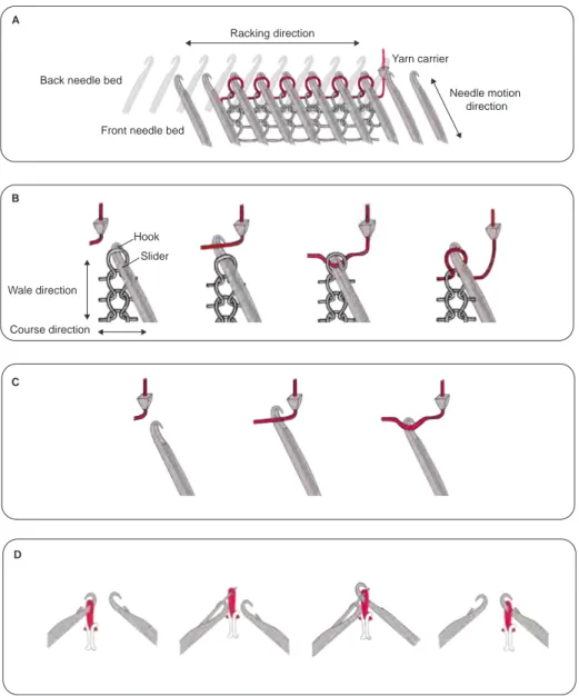
(SWG091N2, Figure 3-2) for device fabrication. It has two beds of needles (front and back), which form an inverted ‘v’ shape. Each needle is composed of a hook, which catches the yarn and holds the topmost loop, and a slider, which is controls by a horizontally moving carriage and actuates the movement of the hook. Three basic needle operations are available to the machine: knit, tuck, and transfer. The knit operation actuates the needles to grab the fed yarn from the yarn carrier, forms a new loop, and pulls it through the existed loop to connect the loops in columns. The tuck operation actuates the needles to grab the yarn and hold it without form-ing a new loop. The transfer operation actuates needles from both beds to pass the existed loop from one bed to the other. Racking is another common digital knitting machine operation, where the back bed shifts laterally to the left or to the right as a whole to create needle offsets during transferring (Figure 3-3). A sequence of racking, transferring and knitting combine, split and move stitches to create short rows, in-creasing and dein-creasing of stitches, which leads to complex 2D/3D fabric geometries and structures (such as gloves and socks).
3.2.1
Inlay
The coaxial piezoresistive fiber is stiffer and thicker than normal knitting yarns (Fig-ure 4-4); therefore, it is incorporated into the fabric by inlaying, a programmable knitting technique performed automatically by a digital knitting machine. It
hori-Back needle bed
Front needle bed
Yarn carrier Hook Slider Needle motion direction A B C D Racking direction Wale direction Course direction
Figure 3-3: Illustration of A. important components of commercial digital knitting machine (SWG091N2) and operations of B. knit, C. tuck and D. transfer.
zontally integrates yarns into fabrics in a straight configuration without forming loops. To optimize manufacturability and device performance, two methods of inlaying are performed: automatic inlaying and manual inlaying (Figure 3-4).
Automatic inlaying requires the fabric structure of ‘ribs’, which are textured ver-tical stripes created by alternating columns of knit stitches on the front and the back bed. The coaxial piezoresistive fiber is forced to move simultaneously with normal knitting yarn, which is caught by the needles on the two beds and forms alternat-ing knit stitches to hold down the inlaid functional fiber (Figure 3-4A). The ribbed
Figure 3-4: Illustration of A. automatic inlay and B. manual inlay
structure (alternating stitches on the front and back bed) allows the straightforward inlaying design; however, it creates a textured gap when two fabrics are aligned orthogonally to act as a functioning device and lower the sensing sensitivity and accuracy.
Manual inlaying requires consecutive movements of the normal knitting yarn and the coaxial piezoresistive fiber. Three steps of operations are performed. Firstly, spe-cific stitches are moved from one bed to the other; then the coaxial piezoresistive fiber is pulled across; lastly, the displaced stitches are moved back to their original posi-tions to hold the functional fiber in place (Figure 3-4B). A flat inlaid fabric (without ribbed structure) can be fabricated with manual inlay and the design with a contin-uous piezoresistive fiber covered surface can be achieved by alternating the transfer direction (from the front bed to back bed or from back bed to front bed). However, due to fiber stiffness and the limited space between two beds, the coaxial piezoresis-tive fiber can hardly stay down during the second round of stitches transferring and
will be easily caught by the needles, leading to the destruction of fiber functionality. Therefore, the manual inlay cannot be applied to a tube-shaped structure.
We form the sensing matrix by leveraging a double-layer structure, which is ar-ranged by assembling two knitted fabrics with functional fibers inlaid perpendicularly to form a sensing matrix (Figure 4-5A).
3.2.2
Designs of Full-sized Sensing Wearables
A full-size glove, a pair of socks, a t-shirt (sized for an 8-year-old kid) and a conformal robot arm (KUKA) sleeve are fabricated (Figure 4-6). The knitting patterns of socks, gloves and vest are developed based on the pre-loaded designs (Shima Seiki) through Knitpaint [36].
The conformal robot arm outfit design is first generated through stitch mesh mod-eling [48, 27] with given real-size 3D mesh and knitting wales-course ratio. Given the input KUKA arm surface, it is first cut into a mesh, called cut-mesh, with disc topol-ogy to guarantee the resulting knitted garment conformally fits to the KUKA. Then, the cut-mesh is converted into a stitch mesh (quad-dominant mesh) with consistent course/wale labeling. Stitch mesh is an abstractive representation of the knitting structure, where each polygon face represents interlocked yarn structures and is em-bedded with a set of low-level machine instructions to create the corresponding yarn structures. Each face in the stitch mesh (quad-dominant mesh) can represent knit, short-row, increase, or decrease of stitch. Finally, we traced the stitch mesh and scheduled the knitting instructions accordingly. The output knitting instructions are converted into .dat file that can be loaded and performed by the industrial knitting machine. In order to form the sensors, two stitch meshes is generated along two orthogonal directions from the KUKA arm surface. The functional fibers are inlaid mostly in rows without short-row faces to get a larger coverage of the sensing matrix. (Figure 3-5D).
All fabrics and devices in this project are manufactured with weft knitting in half gauge (every other needle is used for operations) through an industrial digital knitting machine (SWG091N2). Two knitted fabrics with specific 2D/3D shapes are arranged
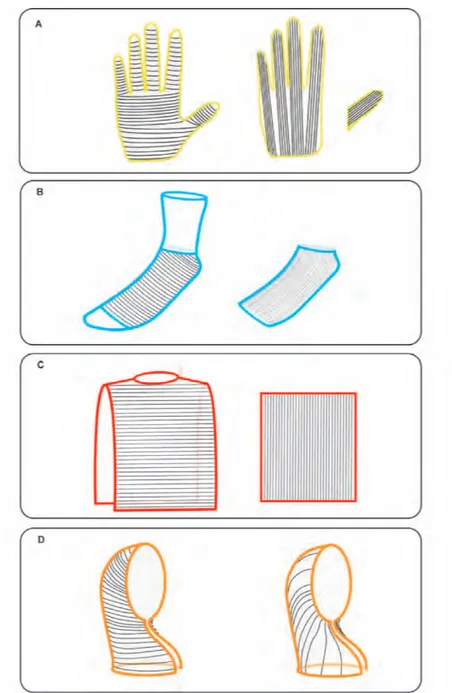
Figure 3-5: Design of full-size A. glove, B. sock, C. vest and D. KUKA sleeve embed-ded with tactile sensing matrix.
as a double-layer structure so that the inlaid function fibers are aligned orthogonally to retrieve the large scale sensing matrix. To optimize the manufacturability and device performance, both automatic inlaying and manual inlaying are exploited. The device designs and the positions of orthogonally aligned functional fibers are shown in Figure 3-5. Cost of each garment can be foudn in Table A.2.
A B C
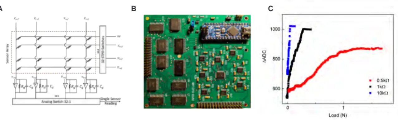
Figure 3-6: A. A modified electrical-grounding-based isolation circuit architecture for passive sensing array readout. B. the designed PCB board c. The response of a single sensor in response to applied load at the output of ADC.
3.3
Data Collection
Electrical connections to the printed circuit board (PCB) are done by performing cuts on the side of knitted garments with an embed sensing matrix. The inlaid coaxial piezoresistive fibers are extended 1-2cm from the main fabric structures by a few tucks away from the main knitting patterns, which allows electrical connections without disrupting the main knitted fabric. A modified electrical-grounding-based circuit architecture (based on Ref. 21) is designed to eliminate most cross-talk and parasitic effects of the passive matrix (Figure 3-6A). The printed circuit board (PCB) can take up to 32 rows and 32 columns of electrodes (1024 sensors) (Figure 3-6B). A reference voltage V𝑟𝑒𝑓 is applied to each column. Controlled by the 32 single-pole
double-throw (SPDT) switches, one row of the sensors is grounded while all other lines are maintained at V𝑟𝑒𝑓; voltage difference across all lines except the measuring
one is maintained at 0V to isolate the signals. A 32:1 analog switch is used as a multiplexer to raster through the columns one by one. An amplifier is added to each column and the gain is set by the feedback resistor R𝑔. The outputs at ADC are
roughly linear with the applied load. The dynamic range of the reading circuit can then be tuned with the feedback resistors. Resistors of 0.5kΩ to 10 kΩ are used as R𝑔 for optimized signal dynamical range for different applications (Figure 3-6C). For
example, since useful information is mostly embedded in higher response from the tactile socks (during movement) and lower response from the tactile gloves (during
grasping), feedback resistors of 1 kΩ and 5 kΩ are used for the readout specifically from the sock and the glove to optimize data extraction. A capacitor of 10 𝜇F Is added in parallel with each feedback resistor to reduce noise. The 32 SPDT switches and 32:1 analog switch are controlled by an Arduino Nano. Each single measure is transformed into a 10-bit digital signal and transmitted serially to a computer.
3.4
Computational pipelines
Using our full-body sensing garments, we then collect a large tactile dataset (over 1,000,000 frames recorded at 14 Hz) featuring various human-environment interac-tions, including object grasping, complex body movement and other daily activities. This section briefly introduces our computational pipelines for sensing correction, classification tasks and human pose predictions.
3.4.1
Sensing Correction
Figure 3-7: A. Procedure for correcting the tactile glove and B. the tactile vest.
Sensor variation and failure are inevitable during scale-up. Living organisms also face this issue; therefore, they developed the ability to adapt their sensory system in the presence of individual sensor failures or variations [12, 10, 37]. We posit that a similar mechanism may provide robust sensing capabilities while relaxing the flawless requirements in sensor fabrication. This is necessary for many applications, as it is impractical to perform individual calibration and correction of our sensing units due
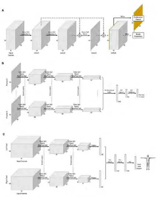
to their high-density, complex geometries, and diverse applications. we develop a self-supervised learning paradigm that learns from weak supervision, using spatial-temporal contextual information to normalize sensing responses, compensate for vari-ation, and fix malfunctioning sensors. In particular, to correct the sensing response from the tactile glove, a person wears the glove and presses a scale with different forces (as shown in Figure 3-7A), and we record the synchronized sensory readings from both the glove and the scale. At each frame, the reading from the scale reflects the sum of force being applied; therefore, the sum of the sensory response is expected to have a linear correlation with the reading from the scale. We train a fully con-volutional neural network (Figure 3-8A) that takes in a small sequence of the raw response and outputs a single frame with the same spatial resolution as the input, representing the calibrated result of the middle frame of the input sequence. The neural network is optimized via stochastic gradient descent (SGD) on two objective functions: one encourages the output to preserve the details in the input and the other objective function restricts the sum of the calibrated results to be as close to the scale as possible.
We employ the same self-supervised learning framework and use the calibrated glove as our new “scale” to process the sensing fabrics with arbitrary shape, such as the vest and robot arm sleeve. Similarly, we collect another dataset by pressing the target garment wearing the calibrated glove (Figure 3-7B) and train a new calibration network with the same architecture and procedure for the target garment.
3.4.2
Classification
To test the discriminative capability of our system, we perform versatile classification tasks using tactile data on daily human activities collected from our full-size sensing wearables. Generally, the classification network takes in a sequence of 45 consecutive tactile frames ( approximately 3 seconds in real-time) on versatile human-environment interactions, including grasping, locomotion, body movement and so on. As shown in Figure 3-8B, we pass each tactile frame through 3 shared convolutional layers. The resulted 45 vectors with a length of 512 after flattening are then passed through a
Figure 3-8: Models for A. sensing correction, B. classification, and C. full-body pose prediction.
bidirectional gated recurrent unit (GRU) [9] and two fully-connected layers to derive the final probabilistic distribution over the classes. We train the model using the standard cross-entropy loss for 20 epochs with Adam optimizer of learning rate 0.001 and batch size of 32.
3.4.3
Pose Prediction
Humans maintain the dynamic balance of the body by redirecting the center of mass and exerting forces on the ground, which results in distinct force distributions on the feet [47, 6]. Motivated by this, we hypothesize that a person’s pose can be further estimated from a change of force distribution over time obtained by our tactile socks as a sequence of pressure maps (Figure 4-15E). Here, the body pose is represented by 19 joint angles spanning over the legs, torso, and arms (Figure 4-15A). We record synchronized tactile data from a pair of sensing socks and a full-body motion capture (Xsens MVN) suit, while the user performs versatile actions, including walking, bend-ing forward, twistbend-ing, lungbend-ing, and so on. The motion capture system is composed of 17 inertial-based sensors, which are mounted on 17 key-points on the human body to record and estimate 19 joints angles during the movement. The real-time pressure imprints from both feet are recorded and fed in the network. The 19 different joints include the joints of legs, arms, and the torso. The collected dataset includes 282,747 frames of concurrent MOCAP and tactile pressure maps, where 236,036 frames are used as the training set, 10,108 frames are used as the validation set, and 36,603 frames are used as the test set.
We train a deep convolutional neural network to predict the 19 different joints of the human body, given the tactile footprints of the person. The architecture of the network is described in Figure 3-8C. The network consists of two convolution layers, which took in a sequence of tactile frames from the socks from time step t-k to time step t+k. The input to the model is 30 consecutive frames of the pressure map of the left and right feet. These layers extract patterns from the 2D signal, and the resulting embedding is then passed through 3 fully connected layers to finally output the predicted relative joint angles of the human body corresponding to the person’s pose at time step t. The relative joint angles are the relative angle transformation of the distal joint with respect to the proximal joint represented in the axis angle format. The network is trained using stochastic gradient descent to minimize the mean squared error between the predicted joint angles and the ground truth. We
trained the network with a batch size of 128 and with a learning rate of 0.01 using the Adam optimizer. It is a design choice to predict the pose in the joint angle space instead of the position space, but the code provided can be easily modified to predict the pose in position space. The collected dataset also contains positions of the different joints that could be used to train such a model.
Chapter 4
Experimental and Learning Results
This chapter demonstrates the experimental characterization on coaxial piezoresis-tive fibers and knitted sensing textiles as well as results on self-supervised sensing correction and human-environment interactions learning.
4.1
Fiber characterization
4.1.1
Morphological Characterization
Figure 4-1: A. Photograph of coaxial piezoresistive fiber (> 100 m) and sensing fabrics. B. Morphology of coaxial piezoresistive fiber under microscope and SEM.
Morphological characterization is done under the optical microscope and the scan-ning electron microscope (SEM) with a voltage of 3-5 kV. All fibers are characterized
without any additional coating. Samples are mounted on carbon tape and further covered with copper tape to enhance the electron conductivity and adhesion. For the cross-sectional view, fibers are carefully cut with a new razor blade to expose the cross-section(Figure 4-1).
4.1.2
Electrical Measurement
C Load (N) Resistance (k Ω ) 8 6 4 2 0 0 1 2 A 0 1 2 0 1 2 3 4 5 6 7 8 R e s is ta n c e (k Ω ) Load (N) Load Readout Circuit Resistance (k Ω ) 0 5000 10000 B 2 1 0 Time (s) DFigure 4-2: The resistance changes of a single sensor (composed of two piezoresis-tive fibers) A. in response to applied normal force and B. during load and unload cycle test (over 1000 repetitions). C. Effect of functional fiber thickness on sensing unit performance. D. Resistance change of an unloaded sensor treated with various temperatures.
A pair of fibers are then orthogonally overlapped to create a sensing unit, which converts pressure (normal force acting on the surface) stimuli into electrical signals. The resistance profile is recorded by a digital multimeter (DMM 4050, Tektronix)
Figure 4-3: Resistance profile of a single sensor composed of coaxial piezoresistive fibers fabricated with A. various copper concentration and B. various graphite con-centration
while controlled normal forces are applied at the sensor by a mechanical tester (Instron 5944). The applied load is controlled at the strain rate of 0.5mm/min. Figure 4-2A shows the measured resistance of our typical sensor drops from 8 to 2kΩ in response to an increasing applied normal force (0.1 - 2N). A 10 N compression load is applied on a sensor (composed of two orthogonal functional fibers without the interference of any textile) for 1000 cycles at a constant strain rate of 10 mm/min and no obvious performance decrease was observed (Figure 4-2B). The electrical profile is influenced by the fiber thickness, which is characterized as (Figure 4-2C). The functional fiber is stable up to 50 ∘C, but its resistance increases with temperature beyond this point, which is measured when heated to various temperature by a hotplate(Figure 4-2D). The performance of sensors is also highly influenced by the composition of the piezore-sistive coating (Figure 4-3). The final optimized mixture has the a composition of 26 wt% graphite, 20 wt% copper and 14 wt% OS2, which results in a reasonable resistance range with optimal variations.
4.1.3
Mechanical Measurement
Tensile test is conducted by a mechanical testing machine (Instron 5984) on the fabricated coaxial piezoresistive fiber (600 𝜇m), stainless steel core fiber, and two different kinds of acrylic knitting yarn (Tamm Petit C4240 and Rebel TIT8000). 10
Figure 4-4: Stress-strain curve of fabricated coaxial piezoresistive fiber and normal knitting yarns from tensile testing.
cm of each fiber was pulled at the strain rate of 5mm/min. The yield tensile strength of the fabricated coaxial piezoresistive fiber is over 6 times larger than the one of acrylic knitting yarn while the ultimate strain of acrylic knitting yarn is over 10 times larger than the one of fabricated coaxial piezoresistive fiber (Figure 4-4). The stiffness of functional fiber leads to the special knitting operation, inlaying, for whole-body sensing garments fabrication.
4.2
Full-sized Sensing Wearables
Figure 4-5A shows an example of a double-layer fabric structure, where the outer layer is fabricated with manual inlaying and the inner layer is fabricated with au-tomatic inlaying. Due to the fabric texture and flexibility, sensor sensitivity and sensing range are highly influenced by the knitting pattern and fabric structures. The influence of fabric structure on sensing matrix performance is characterized as (Figure 4-5B).Sensor composed of two fabrics with automatic inlaid functional fibers has the lowest sensitivity and highest detection range, which makes sense because the ribbed texture creates a gap between two fabrics and lowers the force response.
0 10 20 30 40 50 60 70 80 90 100 101 102 103 104 R e si st a n ce (k Ω ) Load (N) 0 5 10 0 2 4 6 8 10 Resistance (k Ω ) 104 103 102 101 100 0 10 20 30 40 50 60 70 80 Load (N)
Functional fibers without fabrics Functional fibers with fabrics Automatic inlay + manual inlay
Manual inlay Automatic inlay
A B
Figure 4-5: A. Example of a double-layer fabric structure. B. The influence of fabric structures (manual inlay and automatic inlay) on device performance.
Figure 4-6: Automated manufactured full-size tactile A. glove, B. sock, C. vest and D. robot arm sleeve.
full glove with inlaid piezoresistive fiber in the vertical direction (to the finger-pointed direction), a four-finger-shape flat sheet and a thumb-shape flat sheet with inlaid piezoresistive fiber in parallel direction (to the finger-pointed direction) (Figure 3-5A and 4-6A). The sensing matrix is assembled by aligning two flat sheets to the inside of the full glove. Sewing is performed at specific locations to avoid the relative movement between two layers of fabrics.
A sock embedded with 672 pressure sensors is composed of two tube-shape-like fabrics with inlaid piezoresistive fibers in parallel and vertical directions (Figure 3-5B and 4-6B).
A full-size vest embedded with 1024 pressure sensors is knitted in two separate parts: a shaped flat sheet, where the zipper is sewed at the side to be a full vest, with inlaid piezoresistive fiber in the horizontal direction, and a rectangular flat sheet with
inlaid functional fiber in the vertical direction (Figure 3-5C and 4-6C). Two fabrics are aligned and sewed accordingly as a full-size t-vest with tactile sensing matrix.
A conformal robot arm (KUKA) sleeve is knitted in two separate parts generated from the stitch remeshing framework (Figure 3-5D and 4-6D).
These full-sized sensing wearables enable the capturing of human behavior, skills, and crafts, which is essential for cultural preservation, transfer of knowledge, as well as for human and robot performance optimization [50, 2].
4.3
Self-supervised sensing correction
Figure 4-7: A. 15 positions on tactile glove, B. correlation between the tactile reading and the scale’s reading increases. The correlation between the sensory response and references increases for C. the glove, D. the right sock, E. the left sock, F. the vest, and G. the robot arm sleeve.
Our self-supervised model increases the correlation between the tactile response and the reference (reading from scale) from 77.7% to 88.3% (Figure 4-7A to C). Same data collection and training procedure are applied in tactile sock calibration, where correlation increases from 92.4% to 95.8% for the left sock, and from 75.9% to 91.1% for the right sock (Figure 4-7D and E).Correlation between the tactile response and
the reference increases from 32.1% to 74.2% for the vest and from 58.3% to 90.6% for the robot arm sleeve (Figure 4-7F and G).
The self-supervised calibration network exploits the inductive bias underlying the convolutional layers [44], learns to remove artifacts, and produces more uniform and continuous responses (Figure 4-8). It enables the large-scale sensing matrix to be robust against variation among the individual elements and even their occasional disruption, consequently improving the reliability of the measurement.
Figure 4-8: Self-supervised correction results on the tactile A. glove, B. vest, C. sock, and D. robot arm sleeve.
Figure 4-9: A. 26 object classes and B. the confusion matrix from classification.
4.4
Applications
We demonstrate the capability and utility of our platform by leveraging our data for the environment and action classification, motion pattern discovery, and full-body human pose prediction. This section will demonstrate applications of our system spanning human behavior monitoring and learning, human-computer interactions and robot manipulation.
4.4.1
Object Classification
Humans can easily identify an object during grasping, which remains challenging but essential for robot manipulation. Recently, robotic grasping and object manipulation are emerging with progress in multimodal learning across visual and tactile domains [5, 14]. Signatures on human-object grasping were recently studied with a tactile glove [41]. Motivated by these, here we show that our sensing glove can capture tactile characteristics during interactions with objects working as electronic skin for object classification. An object set similar to previous work [41] is used in this study, including 26 daily objects, such as mug, screwdriver, chain, and so on. (Figure 4-9A). A dataset for object classification is recorded while a user manipulated these
Figure 4-10: A. We collect tactile information from a vest with a sensing matrix at the back while the wearer sits, lays, and leans in versatile poses. B. Confusion matrix from poses classification with an accuracy of 99.66%.
26 objects wearing the glove. We recorded 284,442 tactile frames in total during manipulation. Based on the data, our model gave a prediction accuracy of 23.35% for top-1, and 43.20% for the top-3 (Figure 4-9B).
4.4.2
Action Classification
We use tactile information from the two socks worn by a person to identify which ac-tion the wearer is performing. The dataset consists of tactile frames retrieved from a pair of socks when the wearer performs 9 different activities including walking, climb-ing up the stairs, climbclimb-ing down the stairs, fast walkclimb-ing, standclimb-ing on toes, jumpclimb-ing, leaning on the left foot, leaning on the right foot and standing upright (Figure 4-10A). The dataset contains 90,295 frames across the different action categories. The same classification pipeline achieves a top-1 accuracy of 89.61% and a top-3 accuracy of 96.97% (Figure 4-10B).
To further analyze the patterns underlying the signals collected from the socks, we perform principal component analysis (PCA) to visualize their distribution. We use the 12,245 frames from the class of walking in the action classification dataset. We concatenate and flattened the signals from the left and right sock as the high-dimensional representation at each time step, each of which is 2,048 dimensions. We
Figure 4-11: PCA on tactile maps from walking (insets are corresponding tactile frames).
extract the principal components with the highest and the second-highest variance to project the high-dimensional responses to a 2-dimensional space and visualized them in Figure 4-11 The signals naturally form a circular pattern, and the pressure shifts back and forth between the left and right feet as we traverse through the circle.
4.4.3
Interaction Classification
Our full-sized sensing vest shows the force distribution during sitting, standing, reclin-ing, and other actions, which can indicate the wearers’ pose, activity, and the texture of the contacted surfaces. It shows great potential in human-computer interactions and human behavior monitoring (Figure 4-12). We capture a dataset where a wearer performs different poses on versatile surfaces. With the same model and training pro-cedure as object classification and action classification, we achieved 99.66% on the test set in distinguishing different lying postures and supporting surfaces. We further project the high-dimensional sensory responses into 2d space via t-SNE [21], where the recordings from different classes naturally form distinctive clusters, indicating the discriminative power of the vest (Figure 4-13).
Figure 4-12: A. Pressure imprints from different sitting postures and B. tapping with potential application in human-computer interactions.
Our sensing matrix also shows a superior sensitivity than a human’s back [17]. We collect a dataset by pressing models of three letters, i.e., “M”, “I”, and “T”, against the back of a manikin wearing the tactile vest from different orientations. The clas-sification network takes a small window of tactile responses and predicts the type and orientation of the letter with an accuracy of 63.76% . When ablating the reso-lution of the sensor, we reassign the value in each 2x2 grid with the average of the four values, which reduces the effective resolution to 16x16. We then use the same classification training pipeline to obtain the accuracy. A similar procedure is em-ployed for calculating the accuracy for sensors with an effective resolution of 8x8, 4x4, and 1x1. Performance drops as the effective resolution decreases from 32x32 to 1x1 (Figure 4-14).
Figure 4-13: A. Photographs of 10 different poses. B. The confusion matrix for classification and C. T-SNE plot from our pose dataset recorded by the tactile vest.
Figure 4-14: A. Example photographs and tactile frames of “M”, “I” and “T” pressed on the tactile vest and B. the confusion matrix for classifying the letter and the orientation. Accuracy drops as sensor resolution decreases.
we further show that ubiquitous sensing wearables can make life more interactive and network things with humans, namely, converge human and machine intelligence.
Figure 4-15: A. Location of the 19 joint angles representing body pose in our model. B. MSE in pose prediction. Influence of C. sensor resolution and D. number of input frames (temporal window) on prediction performance. The dashed line represents the baseline defined as the canonical mean pose of the training data. E. Comparison of various poses recorded by MOCAP (ground truth) and the same poses recovered by our model from the tactile socks pressure frames. Notable errors in the arm region are highlighted in red.
Pressure map retrieved from self-tapping is shown in Figure 4-12B, which shows great potential in human-computer interaction.
4.4.4
Pose Prediction
Our model learns to make accurate predictions that are both smooth and consistent over time, achieving an MSE that is 70.1% lower than our baseline, which always outputs the mean pose. As shown in Figure 4-15B and B-2, our model achieves higher accuracy for the poses in the torso and legs compared to the arms. This is congruous with our observation that the force distributions on the feet are mostly affected by lower body movement and the majority of body mass located in the torso [47]. The significance of sensing resolution and temporal information is reiterated as the performance drops with a systematic reduction in either the input resolution of the tactile-pressure map or the context size of the input tactile-frames (Figure 4-15C and D).
Our results indicate that a pair of tactile socks can potentially replace the bulky MOCAP system. Our approach sets the path forward to analyze and study human motion activities without much physical obtrusion in domains like sports, entertain-ment, manufacturing activities, and elderly care. Further, such footprints contain dynamic body balance strategies, which is a valuable instructive paradigm for robot locomotion and manipulation [47, 50].
4.4.5
Robotic Manipulation and Control
Figure 4-16: Tactile feedback from physical interactions with robotic (KUKA) arm with potential applications in robot manipulation and control.
Modern robots are tactile-blind and rely mostly on vision. Robotic manipulation and control, which are restrained when vision is occluded or disabled, will be dra-matically improved with real-time tactile information. The scalable sensing wearable forms conformal coverage on robotic gripper, limbs, and other functional parts with complex 3D geometries, endowing things with sensing capability. Figure 4-16 shows a digitally knitted KUKA sleeve that fits conformally with the robot arm joints. This piece of skin enables robot to feel objects beyond the vision, for example, multi-point collision detection, which is challenging with the KUKA embedded torque sensors. It obtains huge potential in unobtrusive multi-point collision detection and physi-cal human-robot collaboration, which is very challenging with the KUKA embedded torque sensors and advanced computational tools.
Chapter 5
Summary and Future Work
5.1
Summary
This work presents an automated, inexpensive, and scalable manufacturing method that combines functional fibers and whole garment digital machine knitting to pro-duce large scale sensing textiles with more than 1000 sensors that are conformal to arbitrary 3D geometry. A self-supervised sensing correction is developed to normal-ize sensor responses and correct malfunctioning sensors in the array. Conceptual demonstrations of various human-environment interaction learning using our system indicate the possibility of future applications in biomechanics, cognitive sciences, child development, as well as imitation learning for intelligent robots.
5.2
Future work
There are several directions to improve device performance and explore device appli-cations:
∙ The functional fiber is about 10× stiffer than normal knitting yarn and the piezoresistive coating can be easily ripped off by the sharp needles. Due to these limitations in mechanical properties, the functional fiber is currently integrated with garments through inlaying to minimize artifacts; however, inlaying does not form loops and limits the overall fabric stretchability and flexibility. I would
like to explore new fiber fabrication processes for better mechanical properties, which ideally will allow the formation of loops through knitting with the func-tional fiber. Higher flexibility and stretchability will be obtained with fabrics with pure knitting structures for higher compliance and comfort.
∙ Device performance in sensitivity and detection range is affected by fabric tex-tures and patterns. In the future, we should explore versatile textex-tures and patterns which are attainable through digital machine knitting. The difference in device performance can be easily tuned with knitting operations for different applications. For example, lower sensitive sensing matrix can be incorporated at the bottom of a sock for motion monitoring and higher sensitive sensing matrix can be incorporated at the top of a sock for human-computer interactions.
∙ More sensing functionalities can be embedded in the yarn-level for multimodal data capturing. Strain, temperature, humidity and ionic sensors can be devel-oped at the yarn-level. Other than versatile sensing functionalities, more modal-ities, such as actuation and energy harvesting can be embedded at the yarn-level. Versatile functional fibers can be integrated with full-garment through automated programmable large-scale manufacturing.
∙ Most demos in this project demonstrate the application in human activities capturing and monitoring as well as human-computer interactions. Conformal garments with embedded tactile sensing matrix for humanoid robots and robotic hands with complex geometry can be easily manufactured, which can potentially improve robotic manipulation and control through large data-set capturing and real-time tactile feedback.
∙ The ataset in this project was all collected from each individual devices. We would like to collect a synchronized tactile dataset from multiple wearable sensign garments, which will contain more information for systematic human-environment interactions, health condition and behavior signatures. For exam-ple, we can monitor the health conditions of elders through their locomotion
and movements with wearable tactile socks and vest; we can also record and analyze the training data of baseball players with wearable tactile gloves and socks for optimized training strategy.
Appendix A
Tables
Table A.1: Cost estimation for coaxial piezoresistive fiber fabrication. Elements Unit price Needed amount Total price Graphite nanoparticles $388/kg 0.214g/100m $0.083
Copper nanoparticles $438/kg 0.167g/100m $0.073 PDMS $129/kg 0.428g/100m $0.055 OS2 $54.6/kg 0.119g/100m $0.0065
Stainless steel thread $19.68/100m NA $19.68 Coaxial piezoresistive fiber $20/100m NA NA
Table A.2: Cost estimation for full-sized sensing wearables manufacturing. Elements Unit price Needed amount Total price Acrylic knitting yarn $0.23/100m NA NA
Tactile glove NA ˜20m functional fiber $5.15 ˜
500m acrylic yarn
Tactile glove NA ∼20m functional fiber $5.15 ∼500m acrylic yarn
Tactile sock NA ∼20m functional fiber $5.15 ∼500m acrylic yarn
Tactile vest NA ∼40m functional fiber $10.3 ∼1000m acrylic yarn
Tactile robot arm sleeve NA ∼30m functional fiber $7.84 ∼800m acrylic yarn
Appendix B
Figures
Figure B-1: Examples of self-supervised corrected results of tactile A. glove, B. sock, C. vest, and D. robotic arm sleeve.
Figure B-2: The human pose is represented by 19 joint angles in axis-angle represen-tation of three dimensions (illustrated as 3 components).
Figure B-3: Retrieved tactile frames from socks embedded with sensing matrix, ground truth motion from motion caption system (XSens), and corresponding motion prediction for A. lounging, B. squatting, C. twisting, and D. waist-turning.
Bibliography
[1] Smart apparel company -.
[2] Jack A Adams. A closed-loop theory of motor learning. Journal of motor behav-ior, 3(2):111–150, 1971.
[3] Bok Y Ahn, Eric B Duoss, Michael J Motala, Xiaoying Guo, Sang-Il Park, Yujie Xiong, Jongseung Yoon, Ralph G Nuzzo, John A Rogers, and Jennifer A Lewis. Omnidirectional printing of flexible, stretchable, and spanning silver microelec-trodes. Science, 323(5921):1590–1593, 2009.
[4] Ozgur Atalay, William Kennon, and Muhammad Husain. Textile-based weft knitted strain sensors: Effect of fabric parameters on sensor properties. Sensors, 13(8):11114–11127, 2013.
[5] Chiara Bartolozzi, Lorenzo Natale, Francesco Nori, and Giorgio Metta. Robots with a sense of touch. Nature materials, 15(9):921, 2016.
[6] Catherine E Bauby and Arthur D Kuo. Active control of lateral balance in human walking. Journal of biomechanics, 33(11):1433–1440, 2000.
[7] Clementine M. Boutry, Marc Negre, Mikael Jorda, Orestis Vardoulis, Alex Chor-tos, Oussama Khatib, and Zhenan Bao. A hierarchically patterned, bioinspired e-skin able to detect the direction of applied pressure for robotics. Science Robotics, 3(24), 2018.
[8] Kunigunde Cherenack, Christoph Zysset, Thomas Kinkeldei, Niko Münzenrieder, and Gerhard Tröster. Woven electronic fibers with sensing and display functions for smart textiles. Advanced materials, 22(45):5178–5182, 2010.
[9] Kyunghyun Cho, Bart Van Merriënboer, Caglar Gulcehre, Dzmitry Bahdanau, Fethi Bougares, Holger Schwenk, and Yoshua Bengio. Learning phrase repre-sentations using rnn encoder-decoder for statistical machine translation. arXiv preprint arXiv:1406.1078, 2014.
[10] Ravinder S Dahiya, Giorgio Metta, Maurizio Valle, and Giulio Sandini. Tactile sensing—from humans to humanoids. IEEE transactions on robotics, 26(1):1–20, 2009.
[11] Siyuan Dong, Wenzhen Yuan, and Edward H. Adelson. Improved gelsight tactile sensor for measuring geometry and slip. 2017 IEEE/RSJ International Confer-ence on Intelligent Robots and Systems (IROS), Sep 2017.
[12] Adam J Engler, Shamik Sen, H Lee Sweeney, and Dennis E Discher. Matrix elasticity directs stem cell lineage specification. Cell, 126(4):677–689, 2006. [13] Jun Gong, Yu Wu, Lei Yan, Teddy Seyed, and Xing-Dong Yang. Tessutivo:
Contextual interactions on interactive fabrics with inductive sensing. In Pro-ceedings of the 32nd Annual ACM Symposium on User Interface Software and Technology, UIST ’19, page 29–41, New York, NY, USA, 2019. Association for Computing Machinery.
[14] Roland S Johansson and J Randall Flanagan. Coding and use of tactile signals from the fingertips in object manipulation tasks. Nature Reviews Neuroscience, 10(5):345–359, 2009.
[15] Alexandre Kaspar, Liane Makatura, and Wojciech Matusik. Knitting skeletons: A computer-aided design tool for shaping and patterning of knitted garments. In Proceedings of the 32Nd Annual ACM Symposium on User Interface Software and Technology, UIST ’19, pages 53–65, New York, NY, USA, 2019. ACM. [16] Dae-Hyeong Kim, Jong-Hyun Ahn, Won Mook Choi, Hoon-Sik Kim,
Tae-Ho Kim, Jizhou Song, Yonggang Y Huang, Zhuangjian Liu, Chun Lu, and John A Rogers. Stretchable and foldable silicon integrated circuits. Science, 320(5875):507–511, 2008.
[17] Susan J Lederman and Roberta L Klatzky. Haptic perception: A tutorial. At-tention, Perception, & Psychophysics, 71(7):1439–1459, 2009.
[18] Jaehong Lee, Hyukho Kwon, Jungmok Seo, Sera Shin, Ja Hoon Koo, Changhyun Pang, Seungbae Son, Jae Hyung Kim, Yong Hoon Jang, Dae Eun Kim, et al. Conductive fiber-based ultrasensitive textile pressure sensor for wearable elec-tronics. Advanced materials, 27(15):2433–2439, 2015.
[19] Rui Li, Robert Platt, Wenzhen Yuan, Andreas ten Pas, Nathan Roscup, Man-dayam A Srinivasan, and Edward Adelson. Localization and manipulation of small parts using gelsight tactile sensing. In 2014 IEEE/RSJ International Con-ference on Intelligent Robots and Systems, pages 3988–3993. IEEE, 2014.
[20] Mengmeng Liu, Xiong Pu, Chunyan Jiang, Ting Liu, Xin Huang, Libo Chen, Chunhua Du, Jiangman Sun, Weiguo Hu, and Zhong Lin Wang. Large-area all-textile pressure sensors for monitoring human motion and physiological signals. Advanced Materials, 29(41):1703700, 2017.
[21] Laurens van der Maaten and Geoffrey Hinton. Visualizing data using t-sne. Journal of machine learning research, 9(Nov):2579–2605, 2008.
[22] Jeffrey Mahler, Matthew Matl, Vishal Satish, Michael Danielczuk, Bill DeRose, Stephen McKinley, and Ken Goldberg. Learning ambidextrous robot grasping policies. Science Robotics, 4(26):eaau4984, 2019.
[23] James McCann. The “knitout” (.k) file format. [Online]. Available from: https: //textiles-lab.github.io/knitout/knitout.html, 2017.
[24] James McCann, Lea Albaugh, Vidya Narayanan, April Grow, Wojciech Matusik, Jennifer Mankoff, and Jessica Hodgins. A compiler for 3d machine knitting. ACM Trans. Graph., 35(4):49:1–49:11, July 2016.
[25] Thomas B Moeslund, Adrian Hilton, and Volker Krüger. A survey of advances in vision-based human motion capture and analysis. Computer vision and image understanding, 104(2-3):90–126, 2006.
[26] Douglas Morrison, Peter Corke, and Jürgen Leitner. Closing the loop for robotic grasping: A real-time, generative grasp synthesis approach. arXiv preprint arXiv:1804.05172, 2018.
[27] Vidya Narayanan, Kui Wu, Cem Yuksel, and James McCann. Visual knitting machine programming. ACM Trans. Graph., 38(4):63:1–63:13, July 2019. [28] Jifei Ou, Daniel Oran, Don Derek Haddad, Joseph Paradiso, and Hiroshi Ishii.
Sensorknit: Architecting textile sensors with machine knitting. 3D Printing and Additive Manufacturing, 6(1):1–11, 2019.
[29] Ivan Poupyrev, Nan-Wei Gong, Shiho Fukuhara, Mustafa Emre Karagozler, Carsten Schwesig, and Karen E Robinson. Project jacquard: interactive dig-ital textiles at scale. In Proceedings of the 2016 CHI Conference on Human Factors in Computing Systems, pages 4216–4227. ACM, 2016.
[30] Mahdi Rasouli, Yi Chen, Arindam Basu, Sunil L Kukreja, and Nitish V Thakor. An extreme learning machine-based neuromorphic tactile sensing system for texture recognition. IEEE transactions on biomedical circuits and systems, 12(2):313–325, 2018.
[31] Michael Rein, Valentine Dominique Favrod, Chong Hou, Tural Khudiyev, Alexander Stolyarov, Jason Cox, Chia-Chun Chung, Chhea Chhav, Marty Ellis, John Joannopoulos, et al. Diode fibres for fabric-based optical communications. Nature, 560(7717):214–218, 2018.
[32] John A Rogers, Takao Someya, and Yonggang Huang. Materials and mechanics for stretchable electronics. science, 327(5973):1603–1607, 2010.
[33] Hannes P Saal, Benoit P Delhaye, Brandon C Rayhaun, and Sliman J Bens-maia. Simulating tactile signals from the whole hand with millisecond precision. Proceedings of the National Academy of Sciences, 114(28):E5693–E5702, 2017.
[34] Munehiko Sato, Ivan Poupyrev, and Chris Harrison. Touché: enhancing touch interaction on humans, screens, liquids, and everyday objects. In Proceedings of the SIGCHI Conference on Human Factors in Computing Systems, pages 483– 492. ACM, 2012.
[35] Gregor Schwartz, Benjamin C-K Tee, Jianguo Mei, Anthony L Appleton, Do Hwan Kim, Huiliang Wang, and Zhenan Bao. Flexible polymer transis-tors with high pressure sensitivity for application in electronic skin and health monitoring. Nature communications, 4:1859, 2013.
[36] Shima Seiki. Sds-one apex3. [Online]. Available from: http://www.shimaseiki. com/product/design/sdsone_apex/flat/, 2011.
[37] Takao Someya, Zhenan Bao, and George G Malliaras. The rise of plastic bio-electronics. Nature, 540(7633):379–385, 2016.
[38] Adam J Spiers, Minas V Liarokapis, Berk Calli, and Aaron M Dollar. Single-grasp object classification and feature extraction with simple robot hands and tactile sensors. IEEE transactions on haptics, 9(2):207–220, 2016.
[39] Stoll. M1plus pattern software. [Online]. Available from: http://www.stoll. com/stoll_software_solutions_en_4/pattern_software_m1plus/3_1, 2011.
[40] Matteo Stoppa and Alessandro Chiolerio. Wearable electronics and smart tex-tiles: a critical review. sensors, 14(7):11957–11992, 2014.
[41] Subramanian Sundaram, Petr Kellnhofer, Yunzhu Li, Jun-Yan Zhu, Antonio Torralba, and Wojciech Matusik. Learning the signatures of the human grasp using a scalable tactile glove. Nature, 569(7758):698, 2019.
[42] Nguyen Thanh Tien, Sanghun Jeon, Do-Il Kim, Tran Quang Trung, Mi Jang, Byeong-Ung Hwang, Kyung-Eun Byun, Jihyun Bae, Eunha Lee, Jeffrey B-H Tok, et al. A flexible bimodal sensor array for simultaneous sensing of pressure and temperature. Advanced materials, 26(5):796–804, 2014.
[43] Ryan L Truby and Jennifer A Lewis. Printing soft matter in three dimensions. Nature, 540(7633):371–378, 2016.
[44] Dmitry Ulyanov, Andrea Vedaldi, and Victor Lempitsky. Deep image prior. In Proceedings of the IEEE Conference on Computer Vision and Pattern Recogni-tion, pages 9446–9454, 2018.
[45] Sihong Wang, Jin Young Oh, Jie Xu, Helen Tran, and Zhenan Bao. Skin-inspired electronics: an emerging paradigm. Accounts of chemical research, 51(5):1033– 1045, 2018.
![Figure 2-1: A. An optical-based tactile sensor, Gelsight [19] B. Biomimetic electronic skin [7] C](https://thumb-eu.123doks.com/thumbv2/123doknet/14747849.578856/18.918.200.712.285.506/figure-optical-based-tactile-sensor-gelsight-biomimetic-electronic.webp)

![Figure 2-3: A. An Industrial double-bed weft knitting machine, Stoll CMS 730K [39]](https://thumb-eu.123doks.com/thumbv2/123doknet/14747849.578856/20.918.164.756.680.840/figure-industrial-double-weft-knitting-machine-stoll-cms.webp)