Design of Electronics for a High-Resolution,
Multi-Material, and Modular 3D Printer
by
Joyce G. Kwan
B.S., Massachusetts Institute of Technology (2011)
Submitted to the Department of Electrical Engineering and Computer Science in partial fulfillment of the requirements for the degree of Master of Engineering in Electrical Engineering and Computer Science
at the
Massachusetts Institute of Technology September 2013
@Massachusetts
Institute of Technology 2013. All rights reserved.A uthor... I ...a... Department o t Engineering and Computer Science
August 30, 2013
C ertified by...
Associate Professor of Electri al Engineering and
Wojciech Matusik Computer Science Thesis Supervisor
A
Accepted by... ... Albert R. Meyer Chairman, Masters of Engineering Thesis CommitteeAARC8NES
Design of Electronics for a High-resolution, Multi-Material, and Modular 3D Printer
by
Joyce G. Kwan
Submitted to the Department of Electrical Engineering and Computer Science August 30, 2013
In Partial Fulfillment of the Requirements for the Degree of Master of Engineering in Electrical Engineering and Computer Science
ABSTRACT
Electronics for a high-resolution, multi-material, and modular 3D printer were designed and implemented. The driver for a piezoelectric inkjet print head can fire its nozzles with one of three droplet sizes ranging from 6 pL to
26 pL at approximately 10 kHz. The system developed for curing
photopoly-mer materials is low-power, low-cost, and safe, using ultraviolet light-emitting diodes instead of a gas-discharge lamp. Fabrication cost is less than $10,000, but the printer's 600 DPI resolution is comparable to that of industrial 3D printers. Printed objects exhibit detailed features and a gradual transition between materials with different mechanical properties. The printer's mod-ular design allows modification of the printer to employ different fabrication technologies.
Thesis Supervisor: Wojciech Matusik
Acknowledgements
I would like to thank my thesis supervisor Professor Wojciech Matusik for the opportunity to pursue research in the exciting field of 3D printing. It was a great experience working in a multi-disciplinary team of motivated students, postdocs, and research scientists.
Also, I would like to thank my academic adviser Professor Vincent Chan for his words of encouragement throughout my undergraduate and graduate years.
Finally, this thesis would not have been possible without the continuous support from my mother and friends. Thank you. I am grateful to know such wonderful people.
Contents
1 Introduction 13
1.1 Background . . . 13
1.1.1 State of the Art . . . 14
1.1.2 Open Source 3D Printers . . . 15
1.2 Motivation and Goals . . . 17
1.3 Contributions . . . . 18 1.4 Thesis Organization . . . . 19 2 System Overview 21 2.1 Electrical Subsystems . . . 21 2.2 Printing Process . . . 24 2.3 Modular Design . . . 24
3 Electronics Design and Implementation 27 3.1 Workforce 30 Print Head Module . . . 28
3.1.1 Print Head Selection . . . 28
3.1.2 Control Scheme . . . 30
3.1.3 Drive Electronics . . . 33
3.1.4 Power . . . 37
3.2 Artisan 50 Print Head Module . . . 39
3.2.1 Control Scheme . . . 40
3.3 UV LED Module ...
3.4 Positioning and UV LED Control ... 3.5 Feeding System and Temperature Control .
4 Results and Discussion
4.1 Print Results . . . . 4.2 UV LED Module Limitations . . . . 4.3 Workforce 30 Module Layout and Performance 5 Conclusion and Future Work
A Heat Sink Selection B List of Components 42 45 47 51 . . . . . 51 . . . . . 53 . . . . . 56 59 61 63
List of Figures
1.1 Printed object using the Objet Connex500 . . . 14
1.2 Printed object using the MakerBot Replicator 2 . . . . 16
2.1 System block diagram of the 3D printer . . . . 23
2.2 Sequence diagram of a single scan . . . . 25
3.1 Closeup of a piezoelectric inkjet print head . . . . 29
3.2 Drive waveform for Workforce 30 print head . . . . 31
3.3 Timing diagram of Workforce 30 digital signals . . . . 32
3.4 Electronics block diagram for the Workforce 30 module . . . . 33
3.5 Amplifier for Workforce 30 drive waveform . . . . 35
3.6 Custom-designed driver for the Workforce 30 print head .. . 38
3.7 Mechanical mount for the Workforce 30 module . . . . 39
3.8 Drive waveforms for Artisan 50 print head . . . . 40
3.9 FIFO memory in Artisan 50 module . . . . 42
3.10 A render of the mechanical mount for the UV LED module . . 43
3.11 PCB for a set of UV LED's . . . 44
3.12 Block diagram of UV LED and positioning control . . . 45
3.13 Implementation of UV and positioning control . . . . 46
3.14 Block diagram of feeding and temperature control . . . . 47
3.15 Valve drive circuit . . . 49
3.16 Therm istor circuit . . . . 50
4.2 Elastic properties of the slab . . . . 53
4.3 Printed coin with checkerboard pattern . . . . 54
4.4 Printed step pyramid . . . . 54
List of Tables
4.1 Printed vs. CAD dimensions . . . 52 A.1 Values for heat sink selection . . . 62
Chapter 1
Introduction
1.1
Background
Additive manufacturing, commonly known as "3D printing", is rapidly gain-ing interest among designers from a wide variety of disciplines because of its potential in allowing the design and fabrication of objects with complex geometries. The technology has existed for decades, but only recently did it gain popularity when affordable 3D printers began to emerge on the market [18].
All 3D printing follow a similar process: a printer produces a 3D object by successively depositing material in 2D layers one on top of the other. A user creates the 3D object using 3D modeling software from which the printer's software then "slices" the computer-aided design (CAD) model into cross-sections that the printer uses as guidance for printing the 2D layers.
Methods of material deposition generally fall into two categories, raster-or vectraster-or-based printing. In raster-based printing, slices generated from the CAD model are bitmaps, which serve as the basis for the print head to deposit material in discrete droplets. The Stratasys Objet Connex series and 3D Systems ZPrinter series are examples of raster-based 3D printers [25, 27]. In vector-based printing, slices are composed of vector paths that
Figure 1.1: A printed object using the Objet Connex500 demonstrating the printer's multi-material and high-resolution capabilities [13].
direct the path of continuous material deposition, a process used in fused deposition modeling (FDM). The MakerBot Replicator series are examples of vector-based 3D printers using FDM technology [19].
1.1.1
State of the Art
Currently, only the Objet Connex series can produce both high-resolution and multi-material objects. For a single object, the Objet Connex series can print with up to 14 digital materials composed of two different materials at a resolution of 600 by 600 DPI and 16 pm thickness using inkjet print heads [25]. Their materials library has a variety of mechanical and optical properties, ranging from transparent and rigid to opaque and elastic. An object printed by the Objet Connex500 demonstrating the printer's abilities can be seen in figure 1.1. However, the printers' high cost (the Objet Connex500 costs $250,000) prevents most potential users from accessing them [2].
printers in the 3D Systems ZPrinter series are currently the only 3D printers that can produce high-resolution objects in full color. Inkjet print heads are used to achieve 600 by 540 DPI, but a single object can consist of only one material due to limitations of the printing technology, which builds an object by ejecting binder onto a bed of powdered material that acts as both build and support material [27]. Though less expensive than Objet Connex print-ers, the highest performing model (ZPrinter 850) still costs about $100,000 [4].
Recent advances in applications of 3D printing speak to its potential. For example, Sun et al. developed the first 3D printed batteries, lithium-ion microbattery architectures with potential applicatlithium-ion in autonomously powered microelectronics and biomedical devices [26]. Xu et al. demonstrated fabrication of 3D heterogeneous tissue constructs containing multiple cell types using inkjet printing technology [30]. Furthermore, Hoth et al. used inkjet printing technology to fabricate 3% efficient polymer solar cells, which are competitive with other polymer solar cells [14].
1.1.2
Open Source 3D Printers
Interest in 3D printing has grown largely due to the development of low-cost open source 3D printers, such as those developed by Fab@Home, RepRap, and MakerBot, but their capabilities have yet to be competitive with those of industrial 3D printers [9, 21]. For example, the MakerBot Replicator series use FDM technology to achieve a resolution of 100 pm per layer, but objects produced are limited in applicability because low-resolution artifacts are still apparent, as seen in figure 1.2 [19]. Also, the printers are limited to printing with only PLA (polylactic acid) and ABS (acrylonitrile butadiene styrene) thermoplastics.
Fab@Home was a project that released the first multi-material 3D printer to the public by making its design open source. Its goal was to address the closed nature of the 3D printing industry, which only produced expensive
in-Figure 1.2: The printed octopus using the MakerBot Replicator 2 exhibits low-resolution artifacts [7].
dustrial printers at the time, so accessibility and exploration by the end-user were limited. Therefore, it aimed to produce a low-cost, versatile, and modi-fiable printer to accelerate technology innovation and 3D printing's migration to the consumer space.
Interestingly, early open source efforts recognized the "hands-on" aspect of 3D printing, that those interested in 3D printing may want to customize the technology, thus making their designs open source. Indeed, an increasing number of 3D printers have been developed from initial designs, as shown in the RepRap Family Tree [21]. This trend, along with 17 million visits to the Fab@Home website during its first year and 22,000 MakerBot printers sold, indicate there is substantial interest in 3D printing beyond industry and academia [9, 6].
1.2
Motivation and Goals
There is growing interest in 3D printing, but access to high quality 3D print-ing is limited by the high cost of industrial 3D printers. 3D printprint-ing services do exist (e.g., Shapeways, Sculpteo, i.materialise), using industrial 3D print-ers to print user-submitted models and charging by weight and material, but much of the technology itself needs to be addressed by expanding capabilities, optimizing system components, and lowering costs [24, 23, 15]. However, the closed nature of state-of-the-art technology slows technology innovation and limits exploration by the end-user.
Therefore, there is a need to bridge the gap between low-cost and indus-trial 3D printers, making the high performance of indusindus-trial printers more available. To address this, a low-cost 3D printer with print quality compa-rable to that of industrial 3D printers needs to be designed. Specifically, the printer should have the following features:
" Multi-material: The printer can produce objects composed of dif-ferent materials, including materials with conductive, elastic, rigid, opaque, transparent, or refractive properties.
" High-resolution: The printer uses inkjet print heads to obtain a res-olution comparable to that of industrial 3D printers, which is about 600 DPI.
" Modular: The print heads are attached to the printer using a modular system, allowing the attachment of additional print heads to increase print volume as well as the use of different fabrication technologies. " Low-cost: The printer is intended to supply print quality approaching
that of industrial 3D printers, but cost less than $10,000. Costs are kept low by using off-the-shelf components and computational methods when possible.
Such a printer would enable the fabrication of objects that cannot be achieved by existing additive manufacturing technologies. For example, state-of-the-art technology such as Objet Connex printers and ZPrinters can only achieve a limited subset of desired features. As discussed in section 1.1.1, Objet Connex printers can only print with a maximum of two different ma-terials, which although can be combined to produce 14 digital mama-terials, and ZPrinters can print in full color, but at the cost of using only one material. The system proposed would allow multi-material full color 3D printing at 600 DPI resolution. Furthermore, its modular design would allow different fabrication technologies to operate in conjunction (e.g., FDM and inkjet), efficiently producing objects previously considered difficult (e.g., conductive paths within an object) using existing 3D printing technologies.
This project is part of a greater effort aimed to redesign the tool chain of 3D printing, from CAD software to the 3D printer because there are many inefficiencies in current systems. For example, Chen et al. simplified the translation of functional requirements of an object into 3D prints that can be fabricated [5]. Vidimee et al. addressed the computational challenge of processing enormous amounts data of large high-resolution prints [28]. The 3D printer aims to not only provide high quality printing at relatively low cost, but also push the limits of 3D printing technology.
1.3
Contributions
In this thesis, I designed and implemented electronics for a multi-material, high-resolution, modular, and low-cost 3D printer. I achieved high-resolution by using inkjet print heads from commercial desktop printers. A particular challenge is designing a custom driver for the print heads, but I developed a driver for the print heads that can turn on and off each nozzle in the print head and select from three droplet sizes. In addition, the driver can simultaneously fire all nozzles in the print head without significant distortion
in the drive waveform, producing printed objects with detailed features. The print heads are piezoelectric, and therefore are essentially large capacitive loads (300 nF for one print head when all nozzles are firing).
Another challenge is developing a safe and low-cost method to cure pho-topolymer materials. Industrial 3D printers use gas-discharge lamps, which are not practical for the 3D printer for reasons of safety, form factor and cost. Therefore, I designed and implemented a curing system using light-emitting diodes, a low-cost and low-power solution. The curing system can completely cure photopolymers developed in-house, and for materials that require a broader light range or greater power, the addition of a camera flash has proven to be sufficient.
The printer is currently capable of simultaneously printing with two dif-ferent photopolymer materials (one rigid, the other elastic) that can blend as a gradient at 600 DPI. The printer can accommodate up to six fabri-cation modules, but testing has been performed with two modules because development is ongoing and materials feed lines are limited. The printer costs less than $10,000 to fabricate, with costs kept low by using off-the-shelf components when possible and compensating for performance in software.
The 3D printer's modular design allows for customization and the poten-tial to create objects that currently cannot be fabricated due to mechanical limitations. A variety of fabrication technologies (e.g., extruder, inkjet print head, milling cutter) can be employed in a single machine if supporting hard-ware and softhard-ware are implemented. Also, printing area can be increased by mounting more print heads.
1.4
Thesis Organization
This thesis focuses on electronics design for the printer and is organized into five chapters. Information on the printer's mechanical design can be found in Design and Fabrication of a Modular Multi-Material 3D Printer by Lan
[17].
In Chapter 2, I provide the system overview of the 3D printer, summa-rizing each of its electrical subsystems and describing functions involved in the the printing process. In addition, I describe the printer's modular design. In Chapter 3, I discuss major design decisions and detail the design and implementation of each electrical subsystem in the printer. I describe inkjet printing technology, particularly its thermal and piezoelectric variants, in the discussion of print head electronics.
In Chapter 4, I present examples of printed objects demonstrating the 3D printer's current capabilities. The examples show the printer can print detailed features and a blend of different materials. Then, I discuss limita-tions of the curing system and performance of the print head module.
In Chapter 5, I conclude the thesis, summarizing contributions and discussing future goals for the printer. Immediate goals focus on expanding printer capabilities and long-term goals aim to optimize the printer by using computational methods.
Chapter 2
System Overview
This chapter presents the system overview of the 3D printer. Section 2.1 de-scribes each of the printer's electrical subsystems as well as how they operate in relation to one another. Section 2.2 describes the sequence of functions involved in depositing a single pass of material. Finally, section 2.3 describes the printer's modular design that allows modification of the printer.
2.1
Electrical Subsystems
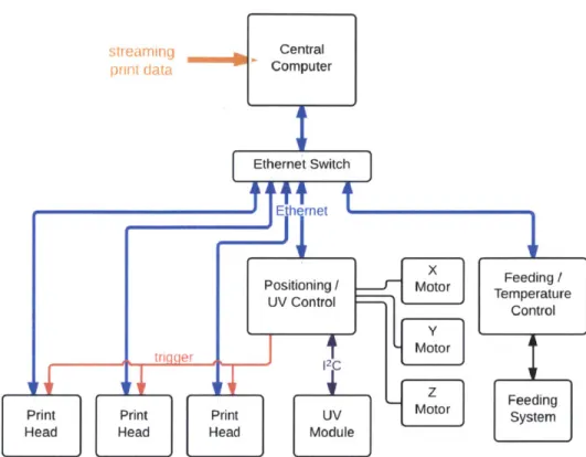
The operation of the 3D printer revolves around a central computer responsi-ble for processing streaming print data into commands for subsystems in the printer, communicating via 100 Mbit s- Ethernet. Specifically, it receives a streaming raster slice from the OpenFab pipeline developed by Vidim~e et al., translates the data into print head format, and performs other rele-vant tasks such as maneuvering the positioning system and turning on or off the UV LED (ultraviolet light-emitting diode) module for curing deposited material [28]. In general, the central computer controls basic functionality of the printer while microprocessors in subsystems are responsible for local control, processing print data sent by the central computer, monitoring the environment, and actuating electromechanical devices among other tasks.
Figure 2.1 shows a block diagram of the printer. The printer consists of the following electrical subsystems:
" Ethernet switch sends commands or data from the central computer to the intended subsystem using 100 Mbit s-1 Ethernet.
* Positioning and UV LED control unit actuates the positioning system by translating commands from the central computer into di-rectives for motor drivers and controls the UV LED module, which cures deposited materials, communicating with the module using the
12C communication protocol [20]. To control the UV LED module, it receives commands from the central computer to turn on or off the UV LED module or adjust intensity of the UV LED's by using a pulse-width modulated (PWM) signal. In addition, it sends a "trigger" signal to print head modules to synchronize material deposition.
" UV LED module is designed to be detachable from the carriage rail and is part of the modular system allowing customization of the printer. The module includes UV LED's for curing deposited photopolymer materials and a cooling system, as the efficiency of the LED's degrades significantly with rising temperature.
" Feeding and temperature control unit regulates the pressure-based feeding system, which delivers materials to the print head ac-cording to pressure levels set by the central computer. To regulate the feeding system, a microprocessor outputs a PWM signal whose duty cycle is constantly updated by a PID (proportional-integral-derivative) algorithm. The microprocessor also regulates the print head's temper-ature, which affects a material's ability to be ejected.
* Feeding system is an electromechanical system that delivers materials to print heads.
sTrearning Central prnt data Computer Ethernet Switch tIEthernet Positioning M Moor UV Control
--Print Print Print UV MOtor
Head Head Head Module
Figure 2.1: System block diagram of the 3D printer. Three ules are shown, but the printer can accommodate up to six ules. Feeding / Temperature Control Feeding System
print head print head
mod-e Print hmod-ead modulmod-es armod-e part of thmod-e modular systmod-em, dmod-etachablmod-e from the carriage rail. A print head module includes a print head and its drive electronics. It synchronizes print data from the central computer and deposits material only when it has received a "trigger" signal. Up to six print head modules can be accommodated on the carriage rail for large volume printing.
2.2
Printing Process
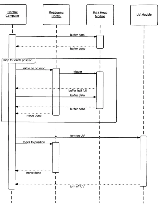
A single pass of material deposition for an object being printed is called a "scan" in the printing industry. Therefore, each slice or layer of the 3D object usually requires several scans. Figure 2.2 shows the sequence diagram of a single scan.
Print data from the central computer is buffered into a print head module until memory in the module is full. The printing process begins: the central computer directs the positioning system to move to the position where the scan begins. Then, the positioning system sends a "trigger" signal to the print head module, signaling it to eject material. The print head module informs the central computer when its buffer memory is half full and the central computer responds with more print data. When buffering has ended, the printing process repeats until the final position of the scan has been reached. If a photopolymer material was used, the central computer turns on the UV LED module to cure the scan. It then directs the positioning system to move to the beginning of the scan and moves the UV LED module across the scan to cure it. The process is then repeated for the next scan.
2.3
Modular Design
The printer is designed to be modifiable through a modular system. There-fore, additional print heads can be attached to increase print area or differ-ent fabrication technologies can be operated by the same printer. In addi-tion, a modular design allows different fabrication technologies to operate in conjunction, efficiently producing objects previously considered difficult to
achieve.
Print heads and accompanying accessories are designed as modules such that they are detachable with software responding accordingly. Modules are mounted onto a rail attached to the carriage that can accommodate up to six print head modules. The rail does not have fixed positions for modules
Positioning
ControJ.
buffer data
[] ... ... u3ffer done....
loop for each position
move to position
triqger
buffer half tful buffer done
move done
move to position
mov e d one J
4...
turn off UV.
Figure 2.2: Sequence diagram for a single pass of material deposition. A printed object requires several iterations of this sequence.
UV Module A turn nn I JV -T, I I .Central Computer Print Head Module
because the design intends for calibration in software, hence modules are slid onto the rail and tightened into place with thumbscrews.
Chapter 3
Electronics Design and
Implementation
This chapter details the design and implementation of each electrical sub-system in the printer. Achieving performance goals is of utmost priority, but when possible, trade-offs are made to lower costs. Design of electron-ics revolves around creating a modular system, so the 3D printer can be customized for specific applications.
Specifically, section 3.1 discusses the selection of printing technology to achieve high-resolution printing and the design of drive electronics for the selected print head. Drive electronics and print head, along with materials feed lines, are designed as a module that can be removed from the printer. Section 3.2 discusses the design of another print head module that uses a different print head to enable a faster printing speed. Section 3.3 details the design of the UV LED module, which is responsible for curing photopolymer materials by using UV LED's, a low-cost, low-power, and safe option com-pared to gas-discharge lamps. Section 3.4 discusses the design of the control unit responsible for controlling the UV LED module and the position system. Finally, section 3.5 discusses the design of the control unit that controls the feeding system and the temperature of the print heads.
3.1
Workforce 30 Print Head Module
This section discusses the design of a print head module to achieve high-resolution multi-material 3D printing first by presenting the reasons behind print head selection and then by detailing the design of electronics to drive the selected print head. The print head requires both digital and analog control signals, which motivate design decisions made in designing drive electronics.
3.1.1
Print Head Selection
Although the printer's modular design accommodates different fabrication technologies, a print head is selected to achieve high-resolution multi-material 3D printing. Inkjet printing technology, which is commonly employed in commercial desktop printers and used in industrial 3D printers, is selected for its high-resolution and ability to dispense digital materials, or a blend of materials.
Two types of inkjet printing technology exist, continuous and drop-on-demand, but drop-on-demand technology is more widely available and lower cost, as continuous inkjet print heads are mostly used in industrial appli-cations, coding and marking different forms of packaging. There are two variants of drop-on-demand technology, thermal and piezoelectric. In the thermal inkjet process, tiny ink chambers each contain a resistive heating el-ement. A burst of current is passed through the heating element to generate heat and vaporize a small fraction of ink in the chamber. The vaporized ink creates a bubble in the chamber, inducing pressure change in the chamber and causing ink to eject through the nozzle attached to the chamber.
The piezoelectric inkjet process induces pressure change in a print head's chambers without heat. Instead of a heating element, piezoelectric material is attached to each chamber. Voltage applied to the piezoelectric material deflects it, the direction and intensity of deflection dependent on the voltage's potential. Deflection changes pressure in the ink chamber and forces ink to
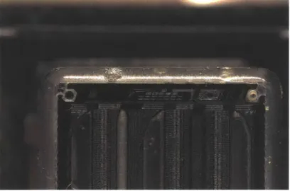
Figure 3.1: A closeup of the piezoelectric inkjet print head from an Epson Workforce 30 printer with its face plate removed.
eject through the nozzle. Therefore, in practice, a piecewise linear voltage waveform is used to control pressure inside the ink chambers, its amplitude, period, and slope critical to the quality and size of the ejected ink droplet. Because of this tight relation between waveform and droplet quality, the waveform needs to be custom designed and optimized for different inks. In general, for drop-on-demand systems, ink chambers are refilled via capillary action, which limits printing frequency to 10 kHz [22]. Figure 3.1 shows a closeup of a piezoelectric inkjet print head with its face plate removed.
The piezoelectric inkjet print head is selected to achieve high-resolution multi-material printing despite being more difficult to control than thermal inkjet technology. Thermal inkjet print heads require only digital signals, whereas piezoelectric inkjet print heads require both analog and digital sig-nals, analog for controlling pressure in the ink chambers and digital for se-lecting nozzles to fire, droplet size, etc. Piezoelectric inkjet print heads are selected primarily because the heat-based firing mechanism of thermal print heads may limit material compatibility by causing adverse reactions.
high performance and low cost, made possible by the large number of desktop printers sold. They have 600 DPI resolution and 540 nozzles that can eject droplets ranging from 6 pL to 26 pL [11]. Multi-material 3D printing can be achieved with only one print head because the Workforce 30 model is a color printer with several independent ink channels. Piezoelectric inkjet print heads by Xaar and Fujifilm were considered, but ruled out because of their high cost. Xaar and Fujifilm print heads cost about $1,000 to $25,000 each depending on the inclusion of drive electronics, whereas Epson's Workforce 30 and Artisan 50 printers respectively cost $80 and $230 each [29, 10, 8].
The Workforce 30 print head is designed to print with four colors (black, cyan, magenta, and yellow) fed through five independent feeding channels, two of them dedicated to black. Its nozzles are organized into three rows of 180 nozzles each, two rows for black and one row divided into three equal sections for cyan, magenta and yellow. Because its feeding channels are independent, the print head can print with up to five different materials.
3.1.2
Control Scheme
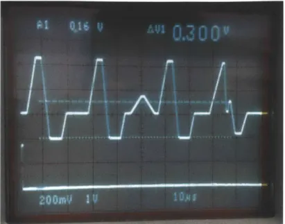
The print head requires an analog waveform to control the pressure in its ink chambers and a set of digital signals for selecting materials, nozzles to fire, and droplet size. One period of the analog "trapezoidal" drive waveform consists of a series of four piecewise linear sub-waveforms, shown in figure 3.2. One period is required to fire a nozzle and applying different combinations of the sub-waveforms to the ink chambers result in different drop sizes ranging from 6 pL to 26 pL.
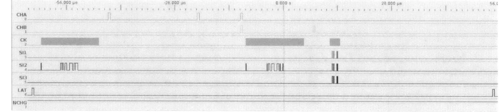
Eight digital signals control printing: NCHG, CHA, CHB, LAT, SI1, S12, S13, and CK. NCHG determines whether the trapezoidal waveform is applied to the ink chambers; CHA, CHB, and LAT indicate the beginning of a sub-waveform; SI1, S12, and S13 determine drop size; and CK is the clock signal. Figure 3.3 shows the timing of the signals. SIx corresponds to a row of nozzles and two bits of data are necessary for each nozzle. Therefore, for
Figure 3.2: One period of the analog drive waveform for the Workforce 30 print head. Applying different combinations of its sub-waveforms to the ink chambers result in different droplet sizes.
one row of 180 nozzles, 180 high bits are first sent to the print head, followed by 180 low bits and finally a sequence that decodes the data into drop sizes. Three drop sizes are possible, 6 pL, 13 pL, and 26 pL.
~56 O0 Os CHI S11 CK .28.000 CON.4S.. 000 ps ... ... ... . ... . ..J ..... ... ... .. I Infili U' 11 FNCHG iy
DAC Amplifier
trigger
AD5424
Microprocessor drive w eform
SRAM
Central Ethernet
Computer transceiver CY7C1041DV33
igital control bus Print head
KS8721BL
STM32F4071G
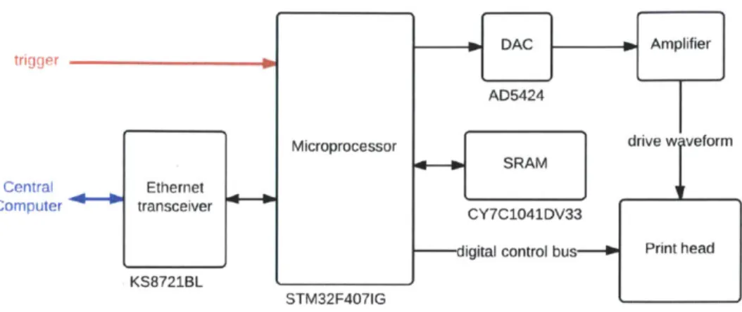
Figure 3.4: Electronics block diagram for the Workforce 30 module.
3.1.3
Drive Electronics
The design of drive electronics for the Workforce 30 print head is motivated by the control signals it requires. An ARM processor (STMicroelectronics STM32F407IG) is selected to be responsible for core functionality of the driver because it can perform complex operations at high speed while al-lowing low-level control characteristic of microprocessors. It processes print data from the central computer into digital signals required by the print head, synchronizing them with the analog drive waveform that is pre-stored in its flash memory. Data is stored in the microprocessor's 192 kbyte of random-access memory, but an external 4 Mbit static random-random-access memory (Cy-press CY7C1041DV33) provides additional buffering of incoming print data. A transceiver (Micrel KS8721BL) interfaces the microprocessor for Ethernet communication. Figure 3.4 shows a block diagram of the module.
An 8-bit digital-to-analog converter (DAC) (Analog Devices AD5424) generates the trapezoidal waveform necessary for firing the print head's noz-zles, its digital input provided by the microprocessor. It is configured in
limit set by the reference voltage. The DAC converts digital words according to equation (3.1) where D is the decimal representation of the digital word loaded to the DAC and n is the resolution of the DAC.
D
Vout = Vref 2 (3.1)
For positive output, -2.5 V is used as the reference voltage, which is gener-ated by a positive 2.5 V reference voltage (Maxim MAX6125) and switched-capacitor charge-pump inverter (Maxim MAX828). The reference voltage and switched-capacitor inverter combination avoids using precision resistors or a negative supply as required by the typical combination of a positive reference and an op-amp inverter [16].
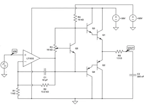
An amplifier is necessary to boost both the voltage and power of the DAC output because the print head requires the trapezoidal waveform to have an amplitude of 33 V. The amplifier, shown in figure 3.5, consists of two stages, the first stage amplifying the voltage and the second stage acting as buffer to supply enough power to the print head. Power boosting is necessary because the print head is essentially a large capacitive load due to its piezoelectric nature. Measured with an impedance analyzer, the print head has a capaci-tance of about 300 nF in the frequency range of interest, which includes the printing frequency (about 10 kHz) and higher frequency components of the analog waveform. The print head's capacitance increases in a roughly linear fashion as more nozzles fire, with 300 nF corresponding to all nozzles firing.
The first stage of the amplifier is an op-amp (Linear Technology LT1632) configured as a non-inverting amplifier to amplify output from the DAC. The LT1632 is selected for its high-bandwidth and rail-to-rail characteristics to preserve high-frequency features of the DAC output and avoid use of a nega-tive supply. Equation (3.2) is the input-output relation for the non-inverting amplifier, showing the gain of the amplifier is established by resistors RI and R2.
R2)t
= -Vin(I + ) (3.2)
VIN + V L 10 k +36V 03 Q1 R3Q5VU 10 k 5 +RS LT1 632 1.50 Q2 s Q4 C1 10 pF >R2 > 13.2 kG +60V
Figure 3.5: The amplifier for the analog drive waveform, consisting of an op-amp configured as a non-inverting amplifier and a Class AB amplifier as the output stage.
The 33 V trapezoidal waveform is obtained by multiplying the DAC output
by a gain of 13.2, with R1 = lkQ and R2 = 13.2kQ.
A power buffer is necessary to drive the print head because voltage am-plification alone does not provide enough power for the print head. This is because the drive waveform has a maximum slope of about 11000 000 V s-1 or 11 V ps- 1 and needs to drive a maximum load capacitance of 300 nF. From the current-voltage relation in equation (3.3) where I(t) is current as a func-tion of time, C is capacitance, and dv(t) dt is change in voltage with respect to time, the print head draws a peak current of 3.3 A.
1(t) - 0dV(t) (3.3)
dt
Then, average current draw can be determined using the peak current in equation (3.4) where trise = 2 ps and tperiod = 25 ps, evaluating to Iavg
-300 mA.
Iavg = Ipeak trise (3.4)
tperiod
The four variants of the trapezoidal waveform are similar enough that Iavg 300 mA can approximate the average current for the entire waveform. Finally, the average power required to drive the print head can be determined using equation (3.5) with Vcc = 36 V to result Pavg = 11 W.
Pavg = lavgVcC (3.5)
The Class AB amplifier topology is selected as the power buffer. It is significantly more efficient than Class A amplifiers and has less crossover dis-tortion than Class B amplifiers [12]. In figure 3.5, resistor R4, potentiometer R3, and transistor Q5 bias the power buffer and Darlington pairs Q1/Q3 and
Q2/Q4
increase the current gain of the amplifier. R4 acts as a simple current source and potentiometer R3 is used for adjustable biasing. Crossover dis-tortion is reduced because the Darlington pairs are biased to conduct evenduring the quiescent state. However, this topology limits output swing to range between 2VBE and Vcc - 2VBE. In practice, this translates to a slight
offset in the output waveform, but as discussed in Chapter 4, does not affect print quality.
Q1
and Q2 are power transistors because they need to source and sink large currents. Models selected (D44H11 and D45H11) provide a balance of speed and power, but need to be cooled with a heat sink because they dissipate most of the power required to drive the print head due to the print head's capacitive nature. Q1 and Q2 are mounted onto the same heat sink (Aavid 578622B03200G), along with bias transistor Q5, to encourage thermal regulation. The heat sink is selected for its small form factor, but more importantly, because it sufficiently prevents the transistors from overheating. Detailed calculation for heat sink selection can be found in Appendix A. PCB implementation and mounting hardware are shown in figure 3.6 and figure 3.7, respectively.3.1.4
Power
The module requires a few different power supplies. Digital circuits operate at 3.3 V, analog circuits require 36 V and 50 V, and the print head is designed to require 3.3 V and 42 V. To minimize the number of power supplies, 36 V powers both analog circuits and the print head instead of using an addi-tional 42 V supply for the print head without visibly affecting print quality. Specifically, the non-inverting amplifier, Class AB amplifier, and print head operate at 36 V, and the current source created from R4 is connected to 50 V, a higher voltage to reduce variation in the current source. The amplitude of the drive waveform is 33 V, but the amplifier operates at 36 V to address the limitation in output swing of the Class AB topology.
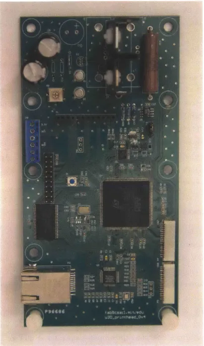
Figure 3.6: The custom-designed driver for the Workforce 30 print head. It measures approximately 3.2 in x 6.3 in, designed to be narrow for a maximum of six print head modules to fit on the carriage rail.
Figure 3.7: The mechanical mount for the Workforce 30 module. It integrates the print head, drive electronics, and materials reservoirs into one module.
3.2
Artisan 50 Print Head Module
Drive electronics for another piezoelectric inkjet print head are designed in addition to the Workforce 30 module. Print heads from a different Epson printer model, the Artisan 50, are used because of their advantages over the Workforce 30 print head. The Artisan 50 print head is very similar, having the same number of nozzles and resolution as the Workforce 30 print head, but the organization of its nozzles is more conducive to uniform printing. They are divided into six rows, 90 nozzles per row and each row is dedicated to one material. Whereas for the Workforce 30 print head, one row is divided for three materials, complicating positioning control algorithms. Furthermore, the control scheme for the Artisan 50 print head allows for printing at almost twice the speed of the Workforce 30 print head. However, the Artisan 50 module has not been implemented.
Figure 3.8: The Artisan 50 print head requires two drive waveforms, which allow a faster printing speed than that of the Workforce 30 print head.
3.2.1
Control Scheme
The Artisan 50 print head has two terminals that need to be driven that are essentially two separate 300 nF capacitive loads. Therefore, two analog waveforms are required to drive the Artisan 50 print head, shown in fig-ure 3.8. The waveforms are similar to the Workforce 30 waveform, but they are interleaved and intervals between firing periods are shorter, causing the Artisan 50 print head to print at almost twice the speed of the Workforce 30 print head.
Artisan 50 digital control signals are also similar to those for the Work-force 30 print head. The Artisan 50 print head has the same number of signals with the same functionality, but its sequence for decoding data is different, largely because the print head requires two analog drive waveforms.
3.2.2
Drive Electronics
Drive electronics are adapted from the Workforce 30 design. Most com-ponents are the same, with only the circuits responsible for generating the analog waveforms differing. A monolithic dual-channel 8-bit DAC (Analog Devices AD5428) configured in unipolar mode generates the two trapezoidal waveforms for driving the print head. The decision to use this DAC rather than two AD5424 DAC's is simply because the microprocessor does not have enough physical pins available. Two amplifiers, one for each waveform, of the same topology as that of the Workforce 30 module amplify the waveforms because load capacitance of each terminal is approximately 300nF.
The addition of a 4kbyte FIFO (first in, first out) memory (Integrated Device Technology IDT72V04L15JG) is necessary because the microproces-sor alone cannot generate two drive waveforms with sufficient resolution. For context, the Workforce 30 module, which uses the same microprocessor, takes advantage of the microprocessor's direct memory access feature at its maxi-mum speed to generate a drive waveform of sufficient resolution. Therefore, to output two waveforms with the same resolution as that of the Workforce 30 waveform, the microprocessor would need to operate twice as fast, which is not possible.
The microprocessor writes waveform data to the FIFO memory, which operates at a faster speed, at startup and uses a clock to advance the mem-ory's pointer during printing, effectively controlling the timing of its output. Waveform data is stored in memory such that data for each waveform is stored in every other address space, shown in figure 3.9, for the memory's output to switch between waveforms. The memory is structured as a 9-bit array and the ninth bit is used to select between the DAC's two output ports.
Waveform A Waveform B Pointer Waveform A Waveform B Waveform A Waveform B To DAC
Figure 3.9: A FIFO memory is necessary for the driver to output two analog drive waveforms with sufficient resolution because the microprocessor cannot operate fast enough.
3.3
UV LED Module
The UV LED module is responsible for curing photopolymer materials and is a part of the modular system. Industrial 3D printers use gas-discharge lamps to cure photopolymers, but for safety and cost, UV LED's are used. Gas-discharge lamps have many advantages over UV LED's, namely, greater in-tensity and broader spectrum to ensure more complete curing, but the danger and cost of developing with them outweigh their benefits. They can be haz-ardous as well because their operation often requires an electrical discharge in the thousands of volts. Commercial curing systems using gas-discharge lamps exist, but they are expensive and would be difficult to incorporate into the printer.
The module includes UV LED's, drive electronics, a cooling system for the LED's, and mirrors to concentrate radiant power, shown in figure 3.10. Pho-topolymer materials used are most sensitive to the 365 nm range, but both 365 nm (LED Engin LZ4-00U600) and 400 nm (LED Engin LZ4-OOUAOO) LED's are used to ensure more complete curing. The PCB for these LED's,
Figure 3.10: A render of the mechanical mount for the UV LED module. The two PCB's, one containing 365 nm LED's and the other 400 nm LED's, are located at the bottom (in green). The module is mounted to the carriage rail using the black connector at top.
shown in figure 3.11, is designed such that four LED's are placed side-by-side as closely as possible to cause radiation patterns of the LED's to overlap for a more uniform distribution. The module holds two PCB's and four LED's of the same wavelength are soldered to a PCB such that one PCB contains 365 nm LED's and the other contains 400 nm LED's.
The LED's are driven by a commercial driver (LEDdynamics A011-D-V-700) that is essentially a DC to DC converter with constant current output. One PCB of four LED's requires two drivers because they are organized in two sets of series LED's and one driver can control two LED's in series. The driver's PWM feature is utilized to adjust brightness of the LED's.
A cooling system prevents the LED's from overheating because their effi-ciency decreases significantly with rising temperature. If not properly cooled, the LED's overheat within a minute and can become permanently damaged.
Figure 3.11: The PCB for a set of LED's. The layout and form factor is the same for both 365 nm and 400 nm sets.
The PCB is designed to facilitate heat transfer, featuring large pads that transfer heat through plated vias to a copper plane on the back of the PCB. It is mounted to an copper heat sink, copper plane facing the heat sink to transfer heat, that is water-cooled. In addition, cooling is performed on the front side of the PCB because much of the heat generated by the LED's does not transfer to the copper plane through the vias. A small fan blows air across the LED's and to prevent air flow from affecting print quality, a piece of glass encases the front side.
A minimum wattage per area is required to cure photopolymer materials, hence mirrors are attached along both sides of the row of LED's to concen-trate power. Aluminum acrylic mirrors are used because they are highly reflective yet low-cost.
encoder N Level shifter encoder TXB0108 Central Ethernet Computer transceiver KS8721BL STM32F4071G Microprocessor tri er Big zi Easy motor Big Y Easy motor Big Z Easy motor IBig Z2 Easy 10 motor Easy motor
Figure 3.12: Block diagram of the subsystem that controls the UV LED module and the x-, y-, and z-axes.
3.4
Positioning and UV LED Control
The UV LED module and positioning subsystem are locally controlled by an ARM development board (Olimex STM32-E407) that translates central com-puter commands to drive signals for motor drivers or 12C format for the UV LED module. A block diagram of the control system is shown in figure 3.12. A level shifter (Texas Instruments TXBO108) shifts the encoders' 5 V output to 3.3 V for compatibility with the microprocessor. To synchronize printing, the microprocessor sends a "trigger" signal to the print head modules.
The positioning system consists of the x-, y-, and z-axes, stepper motors for actuating the axes, stepper motor drivers, and linear encoders for the x-and y-axes. Stepper motors are driven by SparkFun Electronics' Big Easy Driver (ROB-11699), which is essentially a breakout board for the Allegro MicroSystems A4988 microstepping motor driver chip. A total of five po-sitioning motors need to be driven, three for the z-axis platform and one
Figure 3.13: Implementation of the UV LED module and positioning control unit, as shown in the 3D printer. The Olimex STM32-E407 board is located on the left and the stepper motor drivers are on the right.
each for the x- and y-axes. Drivers are integrated into one PCB and con-trolled by the ARM development board, which integrates the STM32F407IG microprocessor and Ethernet transceiver, shown in figure 3.13.
The LED drivers in the UV LED module are controlled by a 16-channel LED controller (NXP PCA9685) capable of outputting 16 independent PWM waveforms. The LED controller receives commands via 12C from the Olimex board, providing the benefit of controlling many components with only two connections. A breakout board for the LED controller is used (Adafruit Industries PID: 815) and mounted on the carriage.
Central 1 be Ethernet Computer transceiver
KS8721BL
Valve Valve drive circuit
Heating Heating
element 4-- drive circuitelement
Microprocessor
STM32F4071G
Figure 3.14: Block diagram of the subsystem and the temperature of the print heads.
16-bit Pesr
-4 8-channel eisur ADC
MAX1300
8-bit Temso
6-ij 8-channel 4- Tcircuistr
ADC rui
MAX1-112
that controls the feeding system
3.5
Feeding System and Temperature
Con-trol
The feeding system and temperature control unit integrates an STM32F407IG microprocessor, drive circuits, and several analog-to-digital converters (ADC) to control the feeding system, which delivers materials to the print head, and the print head's temperature. The print head's temperature needs to be monitored because it affects a material's ability to be ejected. A block di-agram of the subsystem is shown in figure 3.14. It only shows components for controlling one materials feed line and the temperature of one print head, but the subsystem is designed to accommodate several feed lines and print heads.
The microprocessor uses a PID (proportional-integral-derivative) feed-back algorithm to regulate pressure in materials reservoirs according to pres-sure levels set by the central computer. A prespres-sure sensor (Honeywell HSCD-LNN001PDAA3) obtains the current pressure level in a materials reservoir and sends the reading to the microprocessor via a 16-bit ADC (Maxim
MAX1300) as the feedback value for the PID algorithm. The microprocessor then updates the duty cycle of the PWM signal that controls a three-way electromechanical valve responsible for air flow in and out of the materials reservoir. The MAX1300 is selected for its high-resolution and high-speed (115 ksps) specifications in addition to its 8-channel capability because the feeding system requires very sensitive control. High resolution is necessary because the pressure range of interest is relatively small, which from testing is about 2000-5200 on a scale of 65536 using the 16-bit ADC. The ADC's 8-channel capability allows several feed lines to be monitored using only one ADC.
The PWM signal is amplified by a common-emitter amplifier to drive the valve, shown in figure 3.15. Resistor R1 limits current to the base and diode DI dissipates residual power from the valve once the transistor has turned off. Amplifying the drive voltage decreases the valve's response time because the valve is essentially an inductor and resistor in series. However, there is a limit to how much power can be used to drive it because the valve is sensitive to heat. A few drive circuits provide the advantages of reduced response time while decreasing power consumption by about 70%, but the common-emitter amplifier suffices for this application because the valve is not driven at high speed (approximately 60 Hz) and therefore does not need to be driven with a large drive voltage.
In addition to controlling the feeding system, the control unit is respon-sible for the print head's temperature, heating it to increase a material's viscosity and therefore its ability to be ejected and monitoring the print head's temperature. A simple feedback loop controls print head heating. The microprocessor generates a PWM signal, which is amplified and then applied to the heating element, a power resistor. A thermistor (Vishay NT-CALUG02A104H) senses the heating element's temperature and the voltage across the thermistor, which changes with temperature, is converted to a digital value using an 8-bit ADC (Maxim MAX1112). The digital value is
I12V
+ I
"\ square ii
Figure 3.15: The drive circuit for the valve that regulates pressure in a materials reservoir.
communicated using the SPI (Serial Peripheral Interface) protocol to the mi-croprocessor, which updates the duty cycle of the PWM signal accordingly.
The MAX1112 is an 8-channel ADC intended to allow expandability of the
subsystem to monitor several print heads. It is selected for its low cost be-cause temperature does not need to be as sensitively monitored as the feeding system.
To sense the voltage across the thermistor, the thermistor is configured in a voltage divider connected to a precision reference voltage (Linear
Tech-nology LT1461), shown in figure 3.16. The LT1461 is selected for its high
accuracy (0.08%) and low drift (12 ppm/0 C) and it is a series reference, which
is more power efficient for this application compared to a shunt reference [1].
It is important to prevent the thermistor from self-heating or its resistance versus temperature behavior changes from specification and inaccurate read-ings are produced. A good rule of thumb is to limit current through the
thermistor to 100 pA, typically exciting it with 20 piA [3]. Therefore, for the
LT1461 2.5 V IN OUT
+f FVIN C1
GND C2 R2 -1 pF 1 pF 20 kII VSENSE 1 100 kQFigure 3.16: A series reference voltage is used to determine the voltage across the thermistor. A 100 kQ thermistor is selected to prevent self-heating of the thermistor from excessive current draw.
figure 3.16 result in about 20 pA to 90 1iA excitation current depending on
temperature.
Software converts thermistor readings into temperature because thermis-tor resistance is not linear with temperature. The Steinhart-Hart equa-tion (3.6) is used for conversion where T is temperature in kelvin, RT is thermistor resistance at T, and A, B, and C are values provided by the ther-mistor manufacturer. To save computation, values for the temperature range of interest are pre-calculated and stored in the microprocessor's memory as a lookup table that corresponds readings to temperature.
1
T = n )3 (3.6)
Chapter 4
Results and Discussion
Print results show the printer is capable of high-resolution multi-material 3D printing, exhibiting detailed features and gradual transitions between materials. Printer setup can accommodate two Workforce 30 print head modules and three different materials, each material with its own dedicated feeding line. Section 4.1 shows printed objects that are representative of the printer's current capabilities and discusses the causes of artifacts. Section 4.2 discusses the limitations of the curing system, which is the cause of most artifacts. Section 4.3 discusses the performance of the Workforce 30 module and insights gained for implementing the Artisan 50 module, which has not been implemented.
4.1
Print Results
Printed examples using the Workforce 30 module show very fine features can be achieved, as well as gradual transitions between different materials. They closely resemble their CAD models because the central computer compen-sates for droplet characteristics. In figure 4.1, the slab-like object exhibits a gradient in transitioning between two materials with different mechanical properties, one rigid and the other elastic, called "RIG-3" and "ELA-4",
re-Figure 4.1: A printed slab composed of two materials with different mechan-ical properties, one transitioning to the other in a linear fashion.
Length Width Height
CAD Printed CAD Printed CAD Printed
Slab 40 40.5 10 10.1 2 1.8
Coin 20 20.3 19.97 20.2 1.85 1.7
Pyramid 20 20.6 20 20.3 8 7.4
Table 4.1: Dimensions in mm of printed objects compared to those of their CAD models.
spectively. Both photopolymers are developed in-house and one transitions to the other in a linear fashion such that either end is entirely composed of one material. Figure 4.2 shows the slab's elastic properties.
Towards the black end of the slab, the surface becomes less smooth, an artifact due to different printing characteristics of the two materials. For ex-ample, on the same print settings, the materials have different droplet sizes, surface spreading behavior, and curing requirements among other character-istics. Table 4.1 compares the slab's printed dimensions with those of its
CAD model, along with comparisons for other examples.
A coin-like object, shown in figure 4.3, also demonstrates the printer's multi-material capabilities, showing distinct transitions between materials can be printed in addition to gradual ones. The coin is printed with "RIG-3"
-Figure 4.2: The slab transitions from an elastic to a rigid material, hence its shape can be transformed.
in two different colors using one print head module.
A printed step pyramid, shown in figure 4.4, demonstrates the printer's 3D printing capabilities well, but the steps are less defined than in the CAD model. This problem resulted from incomplete curing due to limitations of the current UV LED module design, which are discussed in section 4.2. Another photopolymer material, called "E-20" and also developed in-house, is used to print the pyramid.
Multi-material "dots", as seen in figure 4.5, shows the printer's multi-material capabilities on a small-scale, as these dots measure about 0.5 mm wide and 0.75 mm tall.
4.2
UV LED Module Limitations
Although energy radiated by the UV LED module is concentrated, deposited photopolymer materials often do not cure completely depending on the mate-rial. The core of a deposited droplet cures while its surface does not, causing a reduction of feature size due to spreading of uncured surface material.
Figure 4.3: The checkerboard pattern of the coin demonstrates the printer's multi-material capabilities, showing that distinct transitions between mate-rials can be printed in addition to gradual ones.
Figure 4.4: Curved steps in the pyramid are due to limitations of the current curing system.
Figure 4.5: These "dots", about 500 pm wide, demonstrate the printer's multi-material capabilities on a small scale.
face curing is prevented by the surface's immediate contact with oxygen in ambient air, but the problem can be addressed with a more powerful light source.
A camera flash (Vivitar 285HV), which has a broader light spectrum and radiates more energy, is used and mounted onto the carriage rail in addition to the UV LED module. Although the camera flash is more powerful, testing shows that using both the UV LED module and camera flash produce the best results. From observation, the UV LED module cures the core of the deposited droplets while the camera flash cures their surfaces. However, using a camera flash limits printing speed because each layer requires two flashes to cure and the camera flash can only be turned on every 5 to 10 seconds to prevent overheating.
Some industrial printers, namely the Objet Connex series, address in-complete surface curing by using a roller. The roller moves across a newly
![Figure 1.1: A printed object using the Objet Connex500 demonstrating the printer's multi-material and high-resolution capabilities [13].](https://thumb-eu.123doks.com/thumbv2/123doknet/14686839.560436/14.918.234.642.192.506/figure-printed-connex-demonstrating-printer-material-resolution-capabilities.webp)
![Figure 1.2: The printed octopus using the MakerBot Replicator 2 exhibits low-resolution artifacts [7].](https://thumb-eu.123doks.com/thumbv2/123doknet/14686839.560436/16.918.236.647.195.487/figure-printed-octopus-makerbot-replicator-exhibits-resolution-artifacts.webp)