Design and Implementation of a Sector-Based
Airspace Model for the MIT Extensible Air
Network Simulation
by
Colin J. Whittaker
Submitted to the Department of Electrical Engineering and Computer
Science
in partial fulfillment of the requirements for the degree of
Master of Engineering in Electrical Engineering and Computer Science
at the
MASSACHUSETTS INSTITUTE OF TECHNOLOGY
June 2006
©
Massachusetts Institute of Technology 2006. All rights reserved.
A uthor ...
...
...
Department of Electrical Engineering and Computer Science
May 19, 2006
C ertified by .... ... ... -
...-(
John-Paul Barrington Clarke
Principal Research Scientist
S... -- hesis Supervisor
A ccepted by .... .... . ... ... .. .. . ...
Arth/ur C. Smith
Chairman, Department Committee on Graduate Theses
OF TErCLOGy
OF
TEcARCHIVES
AUG 14 2006
LIBRARIES
Design and Implementation of a Sector-Based Airspace
Model for the MIT Extensible Air Network Simulation
by
Colin J. Whittaker
Submitted to the Department of Electrical Engineering and Computer Science on May 19, 2006, in partial fulfillment of the
requirements for the degree of
Master of Engineering in Electrical Engineering and Computer Science
Abstract
The MIT Extensible Air Network Simulation (MEANS) is a tool that has been de-signed to assist airline schedulers and air traffic managers in predicting flight delays for given air traffic scenarios. One aspect of the simulation, the determination of flight times, has received criticism from the MEANS users as being too simplistic for their needs. Currently, MEANS predicts flight times based on a historical distribution of observed flight times between city pairs. This system ignores the effects of flight level winds and airspace congestion, two major determiners of flight time.
The replacement flight time model presented divides the airspace into discrete sectors based on existing divisions in air traffic control. Each sector has its own wind conditions and capacity limitations which affect passing flights. Results show that, after some calibration, the new flight time model produces accurate flight times when the airspace is divided into ARTCC domains and does not introduce additional errors into other parts of the simulation. Additionally, test scenarios show that the new system is capable of modeling airspace capacity events, such as a radar failure. Comparative results reveal that the old, distribution model produces surprisingly accurate flight times for typical wind conditions and airspace utilization.
Thesis Supervisor: John-Paul Barrington Clarke Title: Principal Research Scientist
Acknowledgments
A number of people have contributed to this work, and I would like to acknowledge them here:
Professor J.P. Clarke for welcoming an outsider into the aerospace world.
Terran Melconian for developing MEANS and its related tools, keeping our servers running, finding my bugs, and much more.
Jonathan Histon for settling the debate on how many planes can fit in the sky at one time.
Bob Hoffman of Metron Aviation for coming through with the sector boundary data.
Elizabeth Bly, Robin Riedel, and everyone else for building MEANS into what it
is today.
Emily Egan for everything.
Contents
1 Introduction and Motivation 13
1.1 Structure of the NAS ... ... ... 14
1.1.1 The Role of Sectors in the NAS . ... 15
1.1.2 The Role of Flight Plans in the NAS . ... 16
1.2 Structure of MEANS ... ... 16
1.2.1 Gate Module ... ... . .... ... 19
1.2.2 Tower Module ... . . ... 19
1.2.3 En Route/Airspace Module . ... 20
1.3 Additional Desired Properties for MEANS . ... 20
2 Design of the Sector-Based Airspace Module 23 2.1 Design Overview ... ... . 23
2.1.1 The Legacy Airspace Specification . ... 24
2.1.2 Required Changes to the Specification . ... 25
2.2 The Sector-Based Airspace ... ... 26
2.2.1 Sectors ... . ... .. ... ... 27
2.2.2 Flight Plans ... ... 28
2.3 Sector Design ... ... .. 29
2.3.1 Capacity and Scheduling ... ... .. ... 29
2.3.2 Sector Transitions ... ... 31
2.3.3 Variations of Flight Acceptance Rules ... ... . 32
2.4 Argmnient for \Iiles-In-Trail Simulation ... ... .. 33
3 Implementation Details and Flight Plan Generation
3.1 Airspace Implementation ... 3.2 Sector Implementation . . ...
3.2.1 Sector Data Structures ...
3.2.2 Requirements and Invariants . ...
3.2.3 Schedule Operations and Correctness . . . . 3.3 Flight Plan Generation . . ...
4 Results and Validation
4.1 Experimental Setup ... . . . . . 4.2 Results ... ..
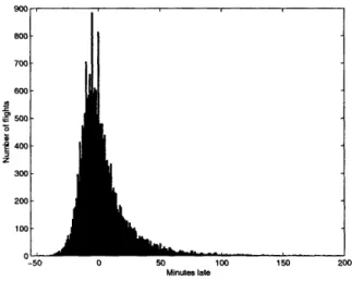
4.2.1 Actual Delay Statistics . . ...
4.2.2 Historical Distribution Implementation . . . . 4.2.3 Sector-Based Implementation: Center Granularity 4.2.4 Sector-Based Implementation: Sector Granularity 4.2.5 Case Study of New York Area .. . ...
4.3 Analysis ... . ...
4.3.1 Flight Duration Correlation . . . . . ..
4.3.2 Acceleration Considerations . ... 4.3.3 Additional Overload Slots . . . ...
5 Conclusions and Future Work
5.1 Future Work ... .. ... 5.1.1 Acceleration Compensation Calibration . . 5.1.2 Aircraft Cruising Speeds . ...
5.1.3 Improved Flight Plans . . ...
5.1.4 Improved Flight Level Wind Data . . . . . 5.1.5 New Airspace Induced Ground Hold Rules
37 .. . . . 37 .. . . . 39 .. . . . 42 .. . . . 44 .. . . . 45 .. . . . 49 53 .. . . . 54 . . . .. . 55 .. . . . . 55 . . . . . . 56 . . . . . 59 . . . . . 62 . . . . . 65 . . . .. . 70 .. . . . 71 .. . . . 74 .. . . . 78 79 . . . .. . 80 . . . . . 80 .. . . . 81 .. . . . 81 .. . . . 81 . . . . . . 81
List of Figures
1-1 ARTCC regions ... ... 14
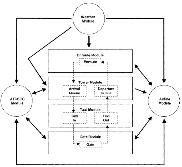
1-2 The relationship of component modules in MEANS . ... 17
3-1 Calculation of sector crossing time . ... . 41
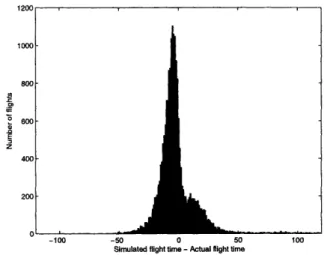
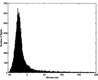
4-1 Actual flight delays ... 55
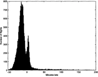
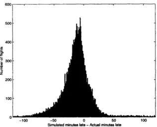
4-2 Flight delays predicted by the historical distribution implementation . 56 4-3 Deviations from actual delays for the historical distibution implemen-tation ... ... .. ... . ... 57
4-4 Deviations from actual flight times for the historical distribution im-plementation ... ... 58
4-5 Flight delays predicted by the sector-based implementation at center granularity ... ... ... 59
4-6 Deviations from actual delays for the sector-based implementation at center granularity ... . ... . 60
4-7 Deviations from actual flight times for the sector-based implementation at center granularity ... ... . 61
4-8 Flight delays predicted by the sector-based implementation at sector granularity ... ... 63
4-9 Deviations from actual delays for the sector-based implementation at sector granularity ... .... ... ... . 63
4-10 Deviations from actual flight times for the sector-based implementation at sector granularity . . ... ... . . . 64
4-11 Deviations from actual delays in the New York area for the historical distribution implementation ... ... . . 65 4-12 Deviations from actual delays in the New York area for the sector-based
implementation at center granularity ... . 66 4-13 Deviations from actual delays in the New York area for the sector-based
implementation at sector granularity . ... 67 4-14 Deviations from actual delays in the New York area with failures for
the sector-based implementation at centers granularity ... . 68 4-15 Flight duration correlation for the historical distribution implementation 72
4-16 Flight duration correlation for the sector-based implementation at cen-ter granularity ... ... 72 4-17 Flight duration correlation for the sector-based implementation at
sec-tor granularity ... .... .... ... ... 73 4-18 Flight delays predicted by the sector-based implementation at center
granularity with modified flight plans . ... 75 4-19 Deviations from actual flight times for the sector-based implementation
at center granularity with modified flight plans . ... 75 4-20 Flight delays predicted by the sector-based implementation at sector
granularity with modified flight plans . ... 76 4-21 Deviations from actual flight times for the sector-based implementation
List of Tables
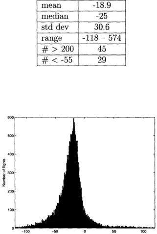
Statistics for figure 4-1 Statistics for figure 4-2 Statistics for figure 4-3 Statistics for figure 4-4 Statistics for figure 4-5 Statistics for figure 4-6 Statistics for figure 4-7 Statistics for figure 4-8 Statistics for figure 4-9 Statistics for figure 4-10 Statistics for figure 4-11 Statistics for figure 4-12 Statistics for figure 4-13 Statistics for figure 4-14 Statistics for figure 4-18 Statistics for figure 4-19 Statistics for figure 4-20 Statistics for figure 4-21 New statistics for figure
. . . . . . . . . 55 . . . . . . . . . . . . . . 5 6 . . . .. . . . . . . . 5 7 . . . . . . . .. . 5 8 . . . . . . . . .. . 6 0 . . . . . . . . . 6 0 . . . . . . . . . . .. . 6 1 . . . . . . . .. . 6 3 . . . . . . . . .. . 6 4 . . . . . . . . . 6 4 . . . . . . . . . . 66 . . . . . . . . . . 6 6 . . . . . . . . . 6 7 . . . . . . . . . 69 .. . . . . . . . . 7 5 .. . . . . . . . . 76 .. . . . . . . . 76 .. . . . . . . . 77
4-9 with additional extra slots. Compare to table 4.9 . ... 4.1 4.2 4.3 4.4 4.5 4.6 4.7 4.8 4.9 4.10 4.11 4.12 4.13 4.14 4.15 4.16 4.17 4.18 4.19
Chapter 1
Introduction and Motivation
The MIT Extensible Air Network Simulation, or MEANS, is a modular simulation tool for researchers to investigate various strategies in air traffic management and airline operations. MEANS provides a high-level simulation of the United States National Airspace System (NAS), where each flight is treated individually. However, MEANS does not attempt to calculate exact flight trajectories or simulate complex flight rules. Instead, MEANS generates realistic flight and passenger delay profiles for the scenario that is input. The complexity of the simulation is minimized, and MEANS executes very quickly, normally simulating a day's worth of air traffic in under five minutes. A researcher can realistically run hundreds of randomized simulations to reduce the impact of errors introduced by simplification on the resulting operational data. This data can then be used in financial models of airline operations to determine the potential cost of the schedule or strategy under investigation. [14]
MEANS provides users with a degree of flexibility through its modular design. Each aspect of the simulation has a number of different interchangeable implemen-tations. The implementations differ on the amount of detail simulated and the data required for execution. Users can choose the implementation that to best suits their needs. If none of the available implementations suit the user's needs, they may ex-tend MEANS with a custom implementation of their own. For example, Elizabeth Bly S.M. 2005 built a custom control tower implementation to optimize takeoff and landing queue ordering. [3]
Figure 1-1: ARTCC regions
One increasingly important air traffic management issue that MEANS could help study is the effects of heavy en route congestion as more and more aircraft try to
fly through the same airspace at the same time. While en route congestion has not
severely impacted air traffic management up to now, the increasing flight load on the NAS is quickly approaching the capacity limits of the current control systems. With a new, detailed model of the NAS, MEANS could help to better understand the effects of airspace congestion and to devise air traffic flow management and control strategies. However, the model must be simple enough to rapidly test a wide array of possible new control strategies. MEANS could prove to be a valuable tool in the effort to redesign the NAS to handle a greater flight load.
1.1
Structure of the NAS
In the United States, air traffic control is provided by a collection of radar centers of various types. At airports, tower radar systems and Terminal Radar Approach CON-trol (TRACON) provide radar support to departing and arriving flights. Airport
han-dling aircraft movements on the ground. TRACONs handle flights on approach and departing as they transition between the airport and cruising altitudes. TRACONs also set holding patterns for aircraft waiting to land. [4] In MEANS, the tower mod-ule performs the duties of the TRACONs and the airport control towers, although the tower module does not handle aircraft movement on the ground (see section 1.2). The Air Route Traffic Control Centers (ARTCC) manage en route flights, ensuring safe aircraft passage through their regions of the national airspace. Approximately 25 ARTCCs provide complete en route coverage for the United States, as shown in figure 1-1 [7]. The airspace/en route module in MEANS simulates the national airspace as a whole, including all of the ARTCCs.
1.1.1
The Role of Sectors in the NAS
Each ARTCC is divided into a number of control sectors. Each sector is typically handled by a single air traffic controller. A sector can only have as many planes in it as the controller can simultaneously handle, as additional aircraft in the sector increase the likelihood of a air safety violation. The flight capacity of a sector is tracked as a Monitor Alert Parameter (MAP). The MAP value for a sector is determined as a function of the average crossing time for flights passing through the sector. Possible values of the MAP value range from five for average crossing times of three minutes or less to eighteen for average crossing times of twelve minutes or more. MAP values can be raised or lowered by up to three at the discretion of the on-duty controllers. When the number of flights in a sector approaches the MAP value, the sector is flagged with a yellow alert, and then a red alert if conditions worsen. Under red alert conditions, flights may be prohibited from entering the sector to avoid unsafe airspace congestion. The maximum capacity of a sector may be temporarily reduced in response to bad weather or equipment malfunctions, as a controller needs to handle each flight more carefully. [8]
When the number of planes in a sector approaches the maximum capacity of that sector, air traffic controllers have several available options to reduce congestion. Controllers can reroute flights to less crowded neighboring sectors if congestionl is
localized. In many situations, controllers enforce a miles-in-trail restriction, forcing flights traveling along the same flight paths to slow down and follow the flight in front of them at a greater distance than normal. While this strategy prevents crowding from reaching dangerous levels, it can cause congestion delays to propagate as the miles-in-trail restriction affects sectors feeding the overcrowded sector. [7]
1.1.2
The Role of Flight Plans in the NAS
When flying at cruising altitude, flights do not typically fly the most direct path to their destination. Instead, they must follow a flight plan. Flight plans consist of series of Air Traffic Service (ATS) routes connected with waypoints. An ATS route is a "route designed for the management of air traffic operations or for the provision of air traffic services." [9] Routes consist of a series of straight segments connected at navigational markers. Sector geometries match the ATS routes in many places, allow-ing some sectors to almost exclusively handle traffic along a certain route. Normally, a flight plan consists of an alternating sequence of ATS routes and waypoints, with the waypoints indicating the points at which the plan switches routes. Waypoint-waypoint and route-route transitions do occur. If two Waypoint-waypoints are close together, no specific connecting route is necessary. If two routes only intersect at one point, specifying a crossover waypoint would be redundant.
The route and waypoint system of flight planning was developed prior to widespread global position systems and can be implemented using beacons and aeronautical land-marks. When all aircraft come equipped with GPS gear, the FAA may convert the current flight planning system into a "free flight" system, allowing for arbitrary way-points. If this change occurs, the arrangement of the sectors will require adjustment to better handle the new flight trajectories.
1.2
Structure of MEANS
The driver of the simulat ion is an event queue. Rather than simulating real time flight mnovements, the evewnt (ueue allows MEANS to only consider a flight when an event
Weather Module
I
Enroute Moduler
---I
r--- Enroute ,4--Y Tower Module rrival Departure !ueue Queue Taxi Module .T,-Taxi Taxi In Out SGate Module I teinvolving that flight reaches the front of the queue. These events include all major state changes, such as pushing back from a gate or arriving at a destination airport's arrival queue. The event queue is sorted according to simulated time of occurrence, so earlier events are processed first. The time of the event at the head of the queue is treated as the current time for the simulation. Time is not allowed to go backwards, so all events added to the queue must have associated times later than the current time. Initially, the event queue is populated with the flight schedule to be simulated. Processing these events generates additional events which propagate the simulation. The MEANS module structure is shown in figure 1-2. Each module simulates a different part of the air transportation network. The modules at the center of the diagram represent simulated phases of a commercial flight. Flights start in the gate module. Once ready to depart, the flight moves from the gate module to the taxi module, to simulate the plane taxiing to its runway. Next, the tower module deter-mines when the flight can take off, considering local weather and airport utilization levels. Once the flight is airborne, the en route, or airspace, module takes control and determines how long the flight takes to fly to its destination. When the flight arrives at its destination, the en route module passes the flight to the arrival queue of the destination control tower module. The tower module decides when this plane can land, again taking local weather conditions and current airport congestion into account. Next, the taxi module moves the aircraft from the runway to its assigned gate. Once back at the gate, the gate module determines how long before the plane is ready to depart on its next leg, including refueling and maintenance time.
Three of the modules simulate peripheral parts of the flight process. The weather module provides weather and weather prediction information to the other modules. This data allows for variable simulated flight rules, ground delay programs, and alter-nate runway utilization. The airline module responds to disruptions in the simulated flight schedule. For instance, if bad weather forces a ground delay program, airlines may cancel some flights to reduce the delays experienced by other flights. The Air Traffic Control System Command Center (ATCSCC) module is responsible for set-ting ground delay programs in response to inc('lement airport weather. If flights are
expected to be unable to land at an airport because of weather-induced capacity constraints, the ATCSCC prevents the aircraft destined for the affected airport from taking off. The delay program holds the aircraft on the ground until they can be as-signed a landing slot at their destination. This system is deas-signed to prevent airborne aircraft from cluttering the airspace around congested airports and wasting fuel.
A summary of the major modules and implementations follows.
1.2.1
Gate Module
The gate module is responsible for determining how long a flight stays at the airport gate before it can push back and taxi to its runway. The exact time is determined prin-cipally by the aircraft's weight class. Mechanical failures and related delays are sim-ulated stochastically. Additionally, the gate module responds to requests for ground delay program from the ATCSCC. If the ATCSCC anticipates that the destination airport of a flight will be congested, it will hold the aircraft on the ground. Several different ground delay program implementations are available in MEANS. The sim-plest never requires a ground delay. More complete implementations declare ground delay programs automatically in response to airport conditions or as specified by an input file. [4]
1.2.2
Tower Module
The tower module is responsible for determining which aircraft are permitted to takeoff and land. Flights that have taxied out to the runway wait in a departure queue until the tower gives them permission to leave. Similarly, flights that have completed their en route travel wait in the tower's arrival queue until the tower allows them to land. The rates at which the tower allows aircraft to takeoff and land are generally limited, though a trivial implementation of the tower module does provide unlimited
tower capacity. One implementation specifies exact arrival and departure rates for each airport based on an input file. More advanced implementations determine the arrival and departure rates fro•il a 1pareto frontier. An experimnental implementation
of the tower dynamically reorders arriving and departing flights to minimize the inter-flight delays.
1.2.3
En Route/Airspace Module
The en route module, also called the airspace module, determines how long the flight takes from the time it takes off until it reaches its destination airport. This time does not include circling the airport or landing; it only includes the time until the flight reaches the arrival queue for the tower at the destination. The most basic implementation of the airspace module calculates the en route time as the scheduled flight duration minus thirty minutes for airport circling and landing. A more refined implementation uses a historical distribution of flight times between airport pairs to estimate the flight time. For airport pairs where no historical data is available, the en route time is function of the scheduled flight time and the distance between the two airports.
1.3
Additional Desired Properties for MEANS
Many of the modules in MEANS provide implementations that closely model real world phenomena. These implementations attempt to capture not just a general sta-tistical distribution but the actual physical process of the real world behavior. By comparison, the airspace implementations is quite limited. In fact, MEANS is inca-pable of simulating certain scenarios because the airspace module cannot provide the required level of detail. Specifically, all current airspace module implementations do not consider air traffic congestion when determining flight times. Without any con-gestion effects, MEANS cannot reasonably model scenarios involving airspace sector capacity reductions due to inclement weather. This also means that MEANS could not currently be used in efforts to redesign the NAS to minimize the impact of an increased en route flight load. Also, the current implementations do not provide any mechanism for modeling high altitude winds, which can dramatically impact flight. times. Furthermore, several of MEANS's partners from the airline industry have
ex-pressed interest in extending MEANS to simulate the European airspace. Without additional fidelity, MEANS cannot be expanded to support the European airspace system, which has far more complicated flight rules than the United States.
The goal of this thesis is to design and implement an improved version of the airspace module. The new airspace model must at least account for congestion effects, individual sector capacity changes, and high altitude winds. With these additional features, MEANS will be capable of simulating the European airspace. Several exist-ing simulations, such as NASA's FACET [6] already provide such detail by precisely calculating all aircraft trajectories as flights respond to airspace conditions while flying to their destinations. However, the new model cannot attempt to precisely calculate individual flight trajectories. Doing so would lengthen the execution times of MEANS unacceptably. Instead, the new model must strike a balance between precision and simplicity, simulating the required effects with as little computing effort as possible. A successful implementation should attempt to model all of the required features, not severely impact execution time, and improve on the per-flight accuracy of the en route travel times from the previous implementations.
Chapter 2
Design of the Sector-Based
Airspace Module
2.1
Design Overview
The new model simulates the en route airspace as a collection of interconnected sectors. Each sector has a single set of local conditions and a set maximum capacity. All winds and capacity restraints apply to the sector as a whole. Flights traverse these sectors as they follow their provided flight plans. These flight plans consist of a series of sector crossings, or a set heading and distance required to cross the sector. This sector crossing information is translated into a sector crossing time based on a formula including the aircraft's airspeed, the required crossing distance and heading, and the current sector wind speed and heading. After a flight completes its crossing of a particular sector, that sector hands it off to the next sector. When the flight reaches the end of its flight plan, the final sector hands the flight off to the destination airport's arrival queue.
This model has been chosen because it mimics all the components of the real world airspace required to meet our simulation goals without introducing unnecessary complexity. Most of the desired simulation detail is derived from the sector conditions as it applies to individual flights. The behavior of the sectors is designed to match
with passing flights. By simulating sectors as discrete units rather than continuous spaces, the new system captures the sector-level effects without incurring the cost of modeling complex internal sector behaviors.
2.1.1
The Legacy Airspace Specification
Before attempting to outline the design for the new airspace model and implementa-tion, the exact programmatic specification of the airspace module in MEANS must be made clear. All airspace implementations inherit two functions from the abstract base class AirspaceBase that defines the airspace interface. The functions are pre-dict() and accept(). The function prepre-dict() takes as parameters a flight and a takeoff time and returns a nonbinding estimate of the time that the flight will reach its des-tination airport. The function accept() is called by the tower module to move a flight from the departure queue to the airspace, more or less a "take off' function. The ac-cept() function takes the same parameters as predict(), a flight and a time of takeoff, which is presumably the current time in the simulation. The accept() fucntion does not return any value to the tower. After the tower calls accept(), it is the airspace's responsibility to set up any necessary events to cause the flight to reach the arrival queue of its destination airport after an appropriate flight time. The current imple-mentations of accept() create an event at the expected arrival time for the flight to trigger the appropriate handoff function.
One important feature of the accept() function is that it does not provide any mechanism to reject incoming flights. Even if the flight is malformed, possibly with an invalid destination airport, the airspace cannot legally notify the caller of accept(). The only possible action for the airspace in such a situation is to crash MEANS. hopefully with a useful error message to the operator. Dropping the offending flight violates the expectations of the module and can lead to undefined behavior elsewhere in the program.
2.1.2
Required Changes to the Specification
In order to properly simulate a capacity constrained airspace, the airspace must have the option of preventing flights from taking off. If the sector into which the flight takes off is overcrowded, the flight must not take off, as doing so would force the sector to exceed its maximum capacity. Unfortunately, the current airspace module specification does not provide any mechanism allowing the airspace to reject flights or notify towers that a flight will be rejected. Without this capacity, the simulation goals are not satisfiable. In order to achieve the stated goals, the airspace specification must be changed. The selected changes should minimize the impact of the modification on the rest of the system to reduce the volume of code refactoring needed to implement the changes.
The specification was modified in two ways to satisfy these requirements. First, a new method was added to airspace interface, check(). The check() method takes the same arguments as predict() and accept(), a flight and a takeoff time. The function check() returns the number of seconds the flight must wait after its desired takeoff time before the airspace will permit it to take off. If the airspace would permit the flight to take off right away, check() will return zero. The check() return value is generally a nonbinding estimate. However, check()'s return value is binding in one special case. If check() returns zero when the provided takeoff time is the current simulation time, then the airspace guarantees that the it will accept the flight on a call to accept() without any additional delay. The second change modifies the calling requirements of the accept() method. The old specification permitted any call to accept(). The new specification requires that for a given call of accept(), a matching call to check() with the same parameters returns zero at the time of the call to accept(). This now allows the airspace module to prevent flights from taking off by returning nonzero values for check().
Adding the new specification for the existing implementations is not difficult. All old, unconstrained airspace implementations may safely return zero for all calls to check(), as these implementations never have any reason to reject a flight. All tower
module implementations need modifications to force them to call check() before they attempt to pass flights to the airspace. If the call to check() is nonzero, the tower skips that flight and allows other flights to take off instead.
Unfortunately, the most advanced implementations of the tower module, those with dynamic reordering of flights waiting to take off, are not compatible with the new specification. Imposing additional delays on the flights in the takeoff queue inter-feres with the dynamic reordering logic. While the reordering logic can be modified to consider airspace imposed takeoff delays, doing so is beyond the scope of this the-sis. Consequently, the sector-based airspace implementation needs to include error checking code to detect if it is operating alongside a noncompliant tower implementa-tion, so that MEANS can gracefully abort with an error message. The older airspace implementations are still compatible with these tower implementations despite the interface change, since they never impose any takeoff restrictions.
2.2
The Sector-Based Airspace
At the core of the new implementation is the class inheriting the airspace module base class, called AirspaceDetailed. The predict() function determines the arrival time at the destination landing queue by querying each sector along the flight's plan and summing up the expected crossing time for each sector. The check() function determines the airspace induced delay by summing up the delay imposed by each sector along the flight path. This value is intended to underestimate the actual delay, since other flights may induce additional delays between the call to check() and the flight's takeoff time. The accept() method first enters the new flight in the module's flight tracking data structures, and then passes the flight to the first sector in its flight plan.
Besides being responsible for providing the external interface for the module, AirspaceDetailed coordinates the various sectors in the simulation with each other and all en route flights. AirspaceDetailed keeps pointers to all of the individual sec-tor objects (see section 3.2 for mnore information on secsec-tors,) in a collection associated
with the name of the sector for easy lookup. Additionally, AirspaceDetailed maintains a catalog of all flight plans used in the current flight schedule. The current design allows only one flight plan per origin-destination city pair, but this could be modified to permit multiple possible flight plans in the future. As flights follow their flight plans, AirspaceDetailed tracks their position in the airspace by associating each flight with a marker indicating which flight plan segment the flight is in. When a flight moves to a new sector, takes off, or lands, AirspaceDetailed updates these markers to accurately reflect the progress of the flight.
From a flight's perspective, the tower first checks with the airspace to make sure that the flight is allowed to take off. If it is, the tower invokes AirspaceDetailed's accept() method, causing the airspace module to initialize the appropriate tracking markers and insert the flight into the first sector on its flight plan. When the sector receives the flight, it schedules a callback in the event queue to trigger the transition of the flight to the next sector. At the time of this callback, the sector checks to see if the next sector on the flight's plan will accept it. If the next sector is open, then the flight makes the transition, all necessary AirspaceDetailed state is updated, and the process repeats in the next sector. If the next sector does not accept the flight, then the callback is rescheduled for a later time. The sector reattempts the transition at that time. The last sector on the flight plan transitions the flight into the arrival queue of the destination airport instead of a subsequent sector. Once the flight has arrived at its destination, AirspaceDetailed clears all remaining state referring to the completed flight, both to free up memory and to ensure that any subsequent legs of the flight are handled correctly.
2.2.1
Sectors
Besides handling flights that are in the process of crossing the sector, a sector must maintain additional state to ensure that the airspace as a whole runs smoothly. Sec-tors must record expected flight crossings, scheduled by flights at takeoff. This in-formation is required for the sector to accurately predict how much delay a future flight will encounter when it attempts to enter the sector. The sum of these delays
is the value returned by AirspaceDetailed's check() function, which is the first guard against airspace overcrowding. Since flights may be delayed en route, all data re-garding expected flight crossings may change, and the structures in which the data is kept must be capable of dynamically modifying the information. Additionally, sectors must track their simulated conditions, including maximum capacity and flight level winds, both of which are used in determining sector crossing times for passing flights.
2.2.2
Flight Plans
Associated with each origin-destination city pair is a flight plan. Each flight plan consists of a series of segments, each segment listing a sector to cross along with the heading and distance of the crossing. With this information, combined with knowl-edge of aircraft cruising speeds and flight level winds, the sectors can approximate the unconstrained crossing time of the flight (see section 3.1 for more information.) AirspaceDetailed maintains a listing of all flight plans. Separately, AirspaceDetailed maintains pointers for each active flight into the flight plan structure indicating that flight's progress. A flight's pointer should point to a segment relating to the sector it is currently in.
Currently, each city pair has only one flight plan associated with it, and every flight making that trip uses that plan. Additionally, the flight plan system does not allow for rerouting en route flights. Without keeping real time positions of every flight, it is not possible to properly calculate a revised flight plan with correct sector crossing distances for arbitrary rerouting. Since such a large amount of resources would be required to simulate this relatively rare feature, explicit rerouting is left out of the new airspace module's design. The effects of rerouting should be captured by other features of the system, principally by time variable sector capacities along with capacity indluced delays.
2.3
Sector Design
While the AirspaceDetailed class is responsible for most of the coordination between sectors and for implementing the airspace interface, the individual sectors handle most of the computational work. The sectors are principally tasked with accepting passing flights and ensuring their correct delivery to the next sector on their flight plans or to their destination airport. In order to fulfill that role, sectors must carry out a number of processes. First, sectors must be capable of handling incoming flights and signaling whether or not they accepted presented flights. Next, the sectors must calculate the crossing time for traversing flights. Using these crossing time, the sectors must then schedule the flights' exits by inserting the appropriate callbacks into the event queue. When the callbacks are triggered, the sectors must then hand the flights off to either the next sectors on their flight plans or their destination airport. If the hand off to another sector fails, then the sector must reschedule the callback for a time when the handoff is expected to succeed. In order to facilitate the process, the receiving sector should provide an indication as to when it will accept a previously rejected flight.
In addition to moving flights across the airspace, sectors play an important role in coordinating flights throughout the system. In particular, sectors must provide information to AirspaceDetailed regarding potential crossing times and delays to entry in response to calls to predict() and check(). In order for the produced information to be meaningful, the sectors must maintain data on future predicted flight crossings. A schedule entry for each crossing flight should be created when that flight takes off, modified if the flight encounters delays, and cleared when the flight has completed its crossing. Consequently, sectors must be capable of performing all calculations coinjecturally, using sector conditions and flight occupancy statistics that will not be in effect until later, if ever.
2.3.1
Capacity and Scheduling
The primary data structure in the sector tracks the current and scheduled occupancy of the sector. This data structure must be capable of supporting all of the roles the
sectors need to fill, as described above. Specifically, the data structure must properly account for all flights that are currently in the sector. Without this, the sector would have no way of knowing whether or not it had reached its maximum capacity. The callbacks that handle the actual mechanics of the flight crossing do not present the sectors with enough information to track sector occupancy. To provide this informa-tion, the data structure needs to handle adding entering flights and removing exiting flights. If a flight's exit is delayed, the sector's data structure must not prematurely remove the flight. Furthermore, the data structure should track the expected exit times for all flights in the sector so that it can produce accurate occupancy reports for future times.
Additionally, the occupancy data structure must catalog scheduled flights that have not yet reached the sector. At takeoff, each flight schedules crossings for each sector for the appropriate time interval. The structure must be capable of processing this information to give correct estimates of future sector occupancy. Furthermore, the structure may be required to reschedule scheduled crossings if flights encounter unexpected delays prior to reaching the sector. Combined with the records of the flights currently in the sector, the data structure should provide a reasonable, accu-rate prediction of sector occupancy for the near future. Flights that have not yet taken off are not included in the structure's listing. Consequently, predicted occu-pancies will not be meaningful for times more than a flight's duration in the future. Fortunately, this sector occupancy information is used for flight planning and should not need occupancy estimates any farther in the future than that. In particular, the information is used to calculating delays for flights waiting to takeoff. Prior to takeoff, the tower must perform a check() call on the flight to ensure that it will not encounter any delays en route to its destination. In order to do this, each sector must know its expected occupancy for the estimated crossing time so that it can report whether or not it can handle the flight. As specified, the data structure should be capable of providing this information.
In general, the occupancy data structure will support two basic operations, up-dates to the schedule information and queries about occupancy at a given time. In
order to support efficient updates, the structure should not require extensive exami-nation or correction of stored records. Ideally, only the records being changed would be modified, and these records could be looked up efficiently. Since each record would catalog either a flight entering or leaving the sector, each record could contain a field for the change in occupancy of the sector at that time. To change the state of the structure, no records other than those directly modified would need correction. How-ever, calculating the scheduled occupancy of the sector at a given time would require a complete traversal of the data structure to sum up all of the individual changes up to that time. On the other hand, to support efficient occupancy queries, the structure should provide lookups of the occupancy itself. This could be implemented by associ-ating each record with the total number of aircraft in or predicted to be in the sector at the time of the record. Of course, any modifications to the structure would require a complete structure traversal to correct all totals to reflect any changes. Since both of these operations are common in sector operations, neither design option is clearly favored. The selected implementation of the structure merges the two possibilities to provide reasonable performance for all standard operations.
2.3.2
Sector Transitions
Once a flight's callback is triggered, the sector must first determine where the flight is headed next. AirspaceDetailed tracks this information and can easily provide it upon request. If there is not a following sector, then the flight has arrived at its destination. The sector transfers the flight to its destination's arrival queue and notifies AirspaceDetailed that the flight has left the airspace. If there is another sector on the flight's plan, then the sector attempts to pass the flight to the next sector. If the next sector accepts the flight, the new sector notifies AirspaceDetailed that the flight has advanced a segment on its flight plan and integrates the flight into its internal structures. All the previous sector has to do is to remove the passed flight
from its data structures. If the next sector is full, it rejects the flight and indicates a delay interval after which it should accept the flight. This interval is calculated 1)v examiiiining the occupancy data structure and finding the next time that the total
occupancy of the sector drops below the maximum capacity. The sector holding the flight must reschedule the transition for the flight, so that the transition will eventually succeed, and update any internal state referring to the flight's exit time. Additionally, the sector should reschedule the crossings for every following sector, so that the scheduled crossings reflect the flight's deviation from its original crossing schedule.
2.3.3
Variations of Flight Acceptance Rules
In most cases, the rules determining whether or not a sector accepts a presented flight are quite simple. The sector accepts flights so long as the total number of flights in the sector does not reach the sector's maximum capacity. Two special cases are required for reasonable operation of the new airspace. First, flights taking off must always be accepted by the first sector on their flight plan. The airspace interface does not permit a flight to be rejected from the airspace entirely, so the first sector must accept the flight even if it causes that sector to exceed its capacity. Tower modules must still call AirspaceDetailed's check() method before attempting to force aircraft into the airspace, so this rule change should not cause sectors to exceed their capacities in practice. This change is only required to guarantee that flights do not get lost during the handoff between the tower and the airspace modules.
The second special case involves sectors at their maximum capacity. Since sectors at their capacity reject incoming flights, deadlock could arise if full sectors require each other to accept flights. If each full sector requires another full sector to accept a flight before it will accept flights, then no progress is possible, and the simulation will not terminate. In order to prevent this problem in most cases, flights originating from full sectors are subject to a different set of acceptance rules. In particular, the receiving sector must accept the flight so long as it does not exceed the sector's capacity by more than one. This rule gives full sectors special access to an occupancy slot unavailable to unconstrained sectors. Since this extra slot is only used to clear potentially deadlocking situations, it does not routinely cause sectors to exceed their normal capacity limits.
The provision of a single extra slot prevents deadlock in all but very rare cir-cumstances. In order for the new system to deadlock, a collection of interdependent sectors must all exceed their capacity by one. This would nullify the specially pro-vided extra capacity slot. Prior to such a situation, all of the interdependent sectors except one would exceed their capacity by one. In this state, the number of available extra slots across collection sectors is one. In order to transition from this prior state to the deadlocking state, the remaining slot must be occupied by a flight entering the collection. The deadlocking flight cannot come from another sector in the collection, as the originating sector would open up a slot in the process. Also, the deadlocking flight cannot come from an outside sector that has not reached its capacity, as its flights are subject to the original acceptance rules. The only possible origin of the deadlocking flight is a temporarily full sector outside of the interdependent collection. The offending sector could be full from a spike in otherwise unconstrained traffic and could force the deadlocking flight into the collection using the special acceptance rule. Since the original acceptance rules rarely resulted in deadlock, and the new rules only fail under specific and unlikely circumstances, this solution is expected to functionally eliminate deadlock from the system.
2.4
Argument for Miles-In-Trail Simulation
In order for the proposed airspace design to be useful, it must simulate real world air traffic effects. While the individual sectors handle unimpeded travel times appropri-ately, it is not clear that a purely capacity limited sector structure can adequately simulate miles-in-trail restrictions. By applying Little's Law from processor architec-ture theory [11] to the aircraft in a sector, it can be shown that a capacity limited system reasonably approximates a miles-in-trail limitation. Little's Law states that the average number of instructions in a processor is the product of the throughput of the processor, in instructions per second, and the latency of each instruction. Rear-ranging terms. the law also states that the throughput of a processor is the average unlim(ber of inistructions "in flight" divided by the latency of each instruction.
Increas-ing the number of simultaneous instructions or decreasIncreas-ing the latency increases the throughput of the processor. Applying this to flights in a sector, the throughput of a sector, in flights per unit time, is the average occupancy of the sector divided by the sector crossing time of a flight. While these flights do not necessarily follow the exact same path, all existing flight paths can be collapsed into a single path for the purpose of this argument. One mapping to the single path case is to assign sector occupancy slots to the different flight paths in a round robin fashion, thereby interleaving the different paths into one.
Little's Law as applied to sector throughput and the single path assumption can be used to demonstrate that a miles-in-trail restriction is identical to a capacity constrained system in terms of sector throughput. First, consider a miles-in-trail restricted sector. The number of flights the sector can handle simultaneously is the sector crossing distance divided by the miles-in-trail distance, since the sector only allows one plane every miles-in-trail miles. The latency is the average crossing time for traversing flights. Notice that the sector throughput decreases as the miles-in-trail distance increases, as the sector can hold fewer flights at the same time. Now, consider a purely capacity constrained sector. The number of flight the constrained sector can handle simultaneously is simply its maximum capacity. The latency is again the average crossing time. By decreasing the maximum capacity of the sector, the maximum throughput of the sector is reduced just the same as if the miles-in-trail distance had been increased. From a sector throughput point of view, there is no difference between increasing a miles-in-trail restriction and decreasing a maximum capacity. While the inter-flight times are not guaranteed to be the same, the ability to simulate the throughput effect a miles-in-trail restriction for a sector is sufficient for MEANS.
Since miles-in-trail restrictions propagate in the real world as congestion spreads, the capacity constrained system should also propagate any throughput reductions that would normally arise. This is indeed the case. When a sector reaches its maximum capacity. additional flights into the constrained sector must wait until a slot opens up.
con-strained sector than if they had been allowed to travel without the transition delay. From the above argument, increasing the latency of the flights reduces the maximum throughput of the adjoining sector. This reduction in throughput correctly simulates the reduction in throughput from the propagation of a mile-in-trail restriction into adjacent sectors. Furthermore, if the congestion does not clear, the sectors neighbor-ing the original overcrowded sector reach their maximum capacities. In this case, the increased latencies and corresponding decrease in throughput spread to additional sectors, simulating the continuing propagation of a miles-in-trail restriction.
Chapter 3
Implementation Details and Flight
Plan Generation
3.1
Airspace Implementation
The implementation of the airspace interface, AirspaceDetailed, is responsible for co-ordinating between sectors, tracking the progress of each flight, and providing the airspace interface. In order to maintain precise control over the sectors, AirspaceDe-tailed creates all of the sectors in the system and stores references to them in a map associating each sector's name with its pointer. This structure holds the primary copies of the pointers to the sectors. Other copies of the pointers can exist, but they cannot be used to destroy the sector objects. Only when this data structure is decon-structed are the individual sectors deleted. While this structure retains the primary copies of each sector, it is only used to help create the flight plans in the system. When the flight plan configuration file is loaded into AirspaceDetailed at startup, the file refers to each sector by name. The sector name map converts the name in the file to a copy of the object reference for the named sector. The sectors are not actually named in the flight plans that AirspaceDetailed stores, (refer to section 2.2.2 for more information on flight plans.) All sector access in the simulation after startup is done through the copies of sector references in the flight plans. By performing the string nanme to reference conversion at startup, the bulk of the simulation can avoid
a potentially expensive map lookup for each sector access.
The flight plans are stored as vectors, with each flight plan vector identified in a map by its origin and destination airports. As mentioned before, there is only one flight plan per origin-destination pair. The data structure could be modified in the future to support multiple flight plans by having each origin-destination pair map to a vector of flight plan vectors. The flight plan associated with each flight is simply the flight plan listed in the map with the appropriate origin and destination. For flights in the air, AirspaceDetailed associates the aircraft with an index into the flight plan vector to track the progress of the flight. Flights that have not taken off and flights that have already landed do not have associated indices. While the index is not publicly visible, sectors can retrieve the current flight plan segment and the next flight plans segment, which is null if the aircraft is on its last segment. Additionally, sectors can request that AirspaceDetailed advance an aircraft to its next segment in response to a sector transition. If the aircraft was previously on the ground, AirspaceDetailed creates an entry for the newly airborne flight and marks that the flight is in its first flight plan segment. If the aircraft was in the last segment of its flight plan, AirspaceDetailed clears the entry for the flight to indicate that the flight is now on the ground.
In addition to tracking the current location of each flight, the position informa-tion associated with each flight is needed to properly reschedule sector crossings for flights that have been delayed en route. When a flight is delayed, AircraftDetailed must notify each sector after the flight's current segment to reschedule the expected crossing. Initial scheduling does not require the position information, as it always contacts each sector except the first sector in the flight plan.
To support the new airspace interface, AirspaceDetailed must provide a predict() method, a check() method, and an accept() method. The function predict() calcu-lates the expected arrival time for a flight at its destination airport given a flight and its takeoff time. AirspaceDetailed calculates this value by querying the sectors associated with each segment on the flight's plan in order. Each sector responds with the expected total crossing time for the sector, the sumn any entrance delay from
overcrowding and the expected flight time for the crossing. The sum of these total crossing times is the total expected duration of the flight, so the expected arrival time is the sum of the crossing times and the takeoff time. Intermediate sums are used to determine the time the flight arrives at each sector on its flight path, so that the sectors can determine the appropriate conditions when calculating the crossing times. The function check() returns the total delay expected for a given flight taking off at the provided time. AirspaceDetailed calculates this value similarly to the calculations in predict(). Intermediate flight time sums are again used to determine the entry time for each of the sectors along the flight plan. However, instead of returning the arrival time, check() returns the sum of the delays. The calculation of the total crossing time for each sector returns the entry delay time in addition to the total crossing time. If the value returned by check() is zero, then no delays are expected for the flight as it follows its flight plan.
Calling accept() triggers AirspaceDetailed to enter the requested flight into the airspace. AirspaceDetailed first calls check() to ensure that the flight is permitted to take off. Next, AirspaceDetailed forces the first sector on the flight's flight plan to accept the flight. Because the airspace interface does not allow the sector to reject the flight, capacity limits for the first sector are ignored. The prior call to check() guarantees that any capacity limits are enforced. In the process of entering the flight into the first sector, the sector calls into AirspaceDetailed to initialize all appropriate tracking state for the flight. Finally, AirspaceDetailed schedules sector crossings for each subsequent sector on the flight's path. The initial sector already contains the flight, so scheduling the flight is unnecessary. When each sector schedules the flight, it returns the expected exit time for the crossing, which is then used for the entrance time for the following sector.
3.2
Sector Implementation
To support AirspaceDetailed, sectors must be able to appropriately enter and exit
provide estimated crossing times for anticipated sector crossings. Entering flights can presented to the sector in three ways. First, flights taking off must be accepted. Sec-ond, flights entering from an overcrowded sector are subject to lenient entrance rules, allowed to exceed the sector's capacity by one. Third, flights entering from uncon-strained sectors are subject to normal entrance rules and cannot cause the sector to exceed the sector's maximum capacity. Once a flight has been accepted, the sector treats flights the same in all three cases. First, a call is made to AirspaceDetailed to increment the flight's location index, then sector checks that it is the current sector according to AirspaceDetailed, ensuring the flight is in the correct sector. Next, the sector calculates the flight time for the crossing according to its current wind con-ditions, the heading and distance of the crossing, and the aircraft's speed. Since a detailed matching of aircraft tail numbers to cruising speeds was not available, all aircraft speeds are approximated as 450 knots, which is a reasonable approximation of the cruising speed for most airliners [12]. Future versions can provide better air-speed estimates for better precision. The exact calculation, summarized in figure 3-1, assumes the aircraft is tracking towards its destination, meaning that the aircraft angles itself to maintain the appropriate ground heading despite any wind. The ef-fective ground speed is w + - /In
2
- wV. Wu is the portion of wind velocity in the direction the aircraft is traveling. The square root is the portion of the aircraft speed in the traveling direction, derived via the Pythagorean Theorem from the aircraft's airspeed, Inl, and the portion of the wind velocity orthogonal to the flight direction, labeled w,. w, and wv are calculated by first subtracting out the flight heading from the wind heading before deriving the vector components of the wind. Finally, all necessary sector state is updated to reflect the new flight and its anticipated exit time.A callback is entered into MEANS's event queue for the calculated exit time. When the callback is triggered, the sector attempts to transition the flight into the next segment of its flight plan. If AirspaceDetailed reports that the aircraft has arrived at its destination, then the sector hands the flight off to the destination arrival queue. notifies AirspaceDetailed that the flight has landed, and logs the transition iii the
ind
eed
79
Crossing time = Crossing distance / lGround speedi Figure 3-1: Calculation of sector crossing time
internal state. If the aircraft is headed into another sector, then if the next sector accepts the flight, then the current sector only logs the flight transition internally, as all additional computational work is handled by the next sector. If the next sector rejects the flight, the next sector gives an estimate for how long the flight will have to wait before being allowed entry. The current sector reschedules the exit of the flight for after the delay, notifies AirspaceDetailed to reschedule all subsequent sector crossings to reflect the added delay, and enters another callback into the event queue for the new exit time.
Sectors handle scheduling and rescheduling crossings in much the same way. The only difference is that when rescheduling a sector crossing, the sector first clears the existing schedule entry. In either case, the expected entry time is provided to the scheduling or rescheduling function, which then calculates the flight time required to cross the sector. The expected exit time is simply the anticipated entry time plus the required transit time. Any delays the flight encounters if it is denied immediate entrance into the next sector are not incorporated into the expected exit time.
To provide estimated crossing times to AirspaceDetailed, the sectors must sum the flight time and any entrance delay due to sector capacity constraints. The flight time calculations are described above. The entry delay is determined by examining the sector's schedule from the requested entry time forward to find the earliest tinme at which the sector would accept an additional flight. The entry delay itself is used by AirspaceDetailed inl the check() calculations and is optionally returned b1 reference