FOR THE UNITED STATES May 12, 1988
DESIGN OF A HIGH-LEVEL WASTE REPOSITORY SYSTEM FOR THE UNITED STATES
May 12, 1988
Report prepared by the following students enrolled in the combined graduate/undergraduate design subjects:
22.033, Nuclear Systems Design 22.33,- Nuclear Engineering Design
for Spring Term 1988 Julio L. Stephen T. Gregory E. Ernesto D. Von B. William R. Russell P. Matthew J. Scott A. Baeza Boerigter Broadbent Cabello Duran
Hollaway, co-project manager Karlberg
Siegel, co-project manager Simonson
Instructor in charge: Prof. M. J. Driscoll MIT Nuclear Engineering Department
77 Massachusetts Avenue Cambridge, Massachusetts 02139
Page Table of Contents i List of Tables V List of Figures vi Abstract viii Acknowledgements ix CHAPTER 1 INTRODUCTION 1 1.1 Foreword 1 1.2 Background 3 1.3 Report Organization 3
1.4 Repository Startup Date 4
CHAPTER 2 SURFACE FACILITIES AND OPERATIONS 7
2.1 Introduction 7
2.2 At-Reactor Operations 12
2.2.1 Introduction 12
2.2.2 Unit Train Concept 12
2.2.3 Storage/Transportation Cask 13
2.2.4 Facilities and Operations 17
2.2.5 Flat Car Design 20
2.2.6 Reactors Without Rail Spurs 20
2.2.7 Off-Normal Events 22
2.3 Transportation 23
2.3.1 Introduction 23
2.3.2 At-Reactor Operations 24
2.3.3 Reactor to Repository Transport 25
2.3.3.1 Regulations 25 2.3.3.2 Transportation Operations 27 2.3.3.3 Highway/Rail/Barge Routing 28 2.3.3.4 Shipment Frequency 28 2.3.3.5 Security 29 2.3.4 At-Repository Operations 30
2.3.5 Public Policy Issues 30
2.3.6 Estimated Costs 32
2.4 Repository Surface Facilities 33
2.4.1 Introduction 33
2.4.2 Facility Siting and Layout 33
2.4.2.1 Primary Surface Facility 33
2.4.2.2 Secondary Surface Facilties 36
2.4.3.4 2.4.3.5 2.4.3.6 2.4.4 2.4.4.1 2.4.4.2 2.4.4.2.1 2.4.4.2.2 2.4.4.3 2.4.4.3.1 2.4.4.3.2 2.4.4.3.3 2.4.4.3.4 2.4.4.3.5 2.4.4.4 2.4.4.4.1 2.4.4.4.2 2.4.4.4.3 2.4.4.4.4 2.4.4.4.5 2.4.4.5 2.4.4.5.1 2.4.4.5.2 2.4.4.5.3 2.4.4.6 2.4.4.6.1 2.4.4.6.2 2.4.4.6.3 2.4.4.6.4 2.4.4.7 2.4.4.7.1 2.4.4.7.2 2.4.4.7.3 2.4.4.7.4 2.4.4.8 2.4.4.8.1 2.4.4.8.2 2.4.4.9 2.5 2.6 CHAPTER 3 3.1 Operations Off-Normal Events Estimated Costs
Repackaging and Handling Facility Introduction
Cask Receiving and Preparation Receiving Area
Air Lock and Decontamination Area Canister Loading Design Description Shielding Equipment Criticality Operations Canister Sealing Design Description Welding Station
Backfi ling/Leak Testing Station Peripheral Operations
Off-Normal Operations Canister Decontamination
Design Description Decontamination Cell
Decontamination Cell to Lag Storage Air Lock Pre-Emplacement Lag Storage
Design Description Shie din and Cooling Storage Layout
Operations
Emplacement Cask Loading Design Description Canister Downloading Emplacement Cask Loading
Off-Normal Events
Off-Normal Events for the Surface Facility Discussion
Remote Recovery and. Decontamination Equipment Estimated Costs
Surface Facility Overall Costs Chapter Summary REPOSITORY SYSTEMS Introduction ii 88 95 95
3.2.1.1 3.2.1.2 3.2.1.3 3.2.2 3.2.2.1 3.2.2.2 3.2.2.3 3.2.2.4 3.2.2.5 3.2.3 3.3 3.3.1 3.3.1.1 3.3.1.2 3.3.1.2.1 3.3.1.2.2 3.3.1.3 3.3.2 3.3.2.1 3.3.2.2 3.3.2.2.1 3.3.2.2.2 3.3.2.2.3 3.3.2.2.4 3.3.2.2.5 3.3.2.2.6 3.3.2.3 3.3.2.3.1 3.3.2.3.2 3.3.3 Technical Criteria Design Assumptions
Waste Form Description and Site Constraints Design Description
Waste Package Design
Waste Package Materials Selection
Waste Package Thermal Environment and Geometric Layout Waste Package Radiologic Considerations
Allowable Pressure Loadings Estimated Costs
Geologic Repository Criteria and Constraints Technical Criteria
Site Constraints Site Geology
Site Specific Geologic Imposed Constraints Design Assumptions
Design Description Design Methodology
Detailed Subsurface Design
Layout and Construction Sequence Shafts and Ramps
Corridors and Emplacement Drifts Waste Emplacement Holes
Ventilation
Ground Water Control Sealing Design
Shaft and Ramp Seals
Other Sealing Considerations Estimated Costs
3.4 Repository Operations 3.4.1 Criteria and Constraints 3.4.1.1 Technical Criteria
3.4.1.2 Site Constraints 3.4.1.3 Design Assumptions
3.4.1.3.1 Radiological Health and Safety 3.4.1.3.1.1 Worker Exposure
3.4.1.3.1.2 Worker Safety and Monitoring
3.4.1.3.1.3 Non-Radiological Health and Safety 3.4.2 Design Description
3.4.2.1 Primary Criteria 3.4.2.2 Construction
3.4.2.3 Canister Transport System 3.4.2.3.1 Vehicle Suspension Design 3.4.2.3.2 Vehicle Truck System 3.4.2.3.3 Vehicle Braking System 3.4.2.4 Emplacement System
3.4.2.4.1 Emplacement Cask
3.4.2.4.1.1 Cask Shielding Determination
iii 97 98 101 105 105 108 114 116 118 118 119 119 120 122 122 129 131 133 134 134 135 137 139 140 140 142 143 143 144 144 147 147 147 148 148 148 149 149 150 151 152 152 152 155 156 156 157 157 159
3.4.2.6 Peripheral Operations
3.4.2.6.1 Underground Repository Radiation Protection 3.4.2.6.2 Underground Repository Environmental Monitoring 3.4.2.6.3 Underground Maintenance
3.4.2.6.4 Underground Rock Crushing Plant 3.4.3 Off-Normal Events 3.4.4 Estimated Costs 3.4.4.1 Capital Costs 3.4.4.2 Operational Costs 3.4.4.2.1 Maintenance Costs 3.4.4.2.2 Personnel Costs 3.4.4.2.2.1 Workers Wages 3.4.4.2.2.2 Dosimetry Costs 3.4.4.2.2.3 Bioassay Costs
3.4.4.2.2.4 Costs of Protective Clothing 3.4.4.2.2.5 Overall Personnel Cost Estimate 3.4.4.2.3 Operational Cost Summary
3.5 Summary 3.6 References CHAPTER 4 4.1 4.1.1 4.1.2 4.1.3 4.2 4.2.1 4.2.2 4.2.3 4.2.4 4.2.5 4.2.6 4.2.7 4.3 4.3.1 4.3.2 4.4 4.4.1 4.4.2 4.5
WASTE DISPOSAL COSTS
Introduction
Motivation and Overview Research Goals
Outline of the Present Work
WADCOM II (Waste Disposal Cost Model II) Background
Outline
Disposal Scenarios and Model Logic Data Requirements
USERFILE,
DATABASE
Output and Review of Cost Components Independent Cost Evaluation
Compiling the Factors Comprising Total System Cost Comparison with WADCOM II Results
Chapter Summary Conclusions
Problems and Future Work Chapter References iv 166 166 166 168 168 168 169 169 170 170 170 170 171 171 171 171 172 173 175 177 177 177 177 177 178 178 178 179 184 184 191 191 196 196 198 198 198 199 201
5.1 Introduction 203
5.2 Summary and Conclusions 203
5.3 Recommendations for Future Work 208
Addendum Critique by Instructor 211
Appendix A Sample DATABASE File
Appendix B DATABASE Definitions and Sources-WADCOM II
Appendix C Sample Output File
Appendix D Additional Summary Cost Matrices
LIST OF TABLES
Table Page
1.1 Ground Rules 2
3.2-1 Spent Fuel Burnups and Ages at Emplacement Normalized 99
to Energy Information Agency (EIA) 1983 Midplane Projections
3.2-2 Year of Emplacement Based on Projected Inventories of 103
Spent Fuel
3.2-3 Photon Release Rates and Energies for Reference PWR Fuel 104
3.2-4 Average Thermal Properties of TSw2 Rock 105
3.2-5 Corrosion Rates of Candidate Waste Container Alloys 111
3.2-6 Average Cracking Time for Commercial Fe-Ni-Cr Alloys 112 Exposed to Boiling MgCl(2) at 154'C
3.2-7 Characteristics of Spent Fuel Assemblies 113
4.1 Definitions of the WADCOM II Nuclear Waste Disposal Paths 180
4.2 WADCOM II USERFILE 185
4.3 WADCOM II USERFILE: Yucca Mountain Repository Project 188
Highlights
4.4 Summary Cost Matrix I: Project Criteria for Yucca 192
Mountain
4.5 Breakdown of the Summary Cost Matrix 193
4.6 Summary Cost Matrix: Independent Evaluation 197
5.1 System Design Highlights 205
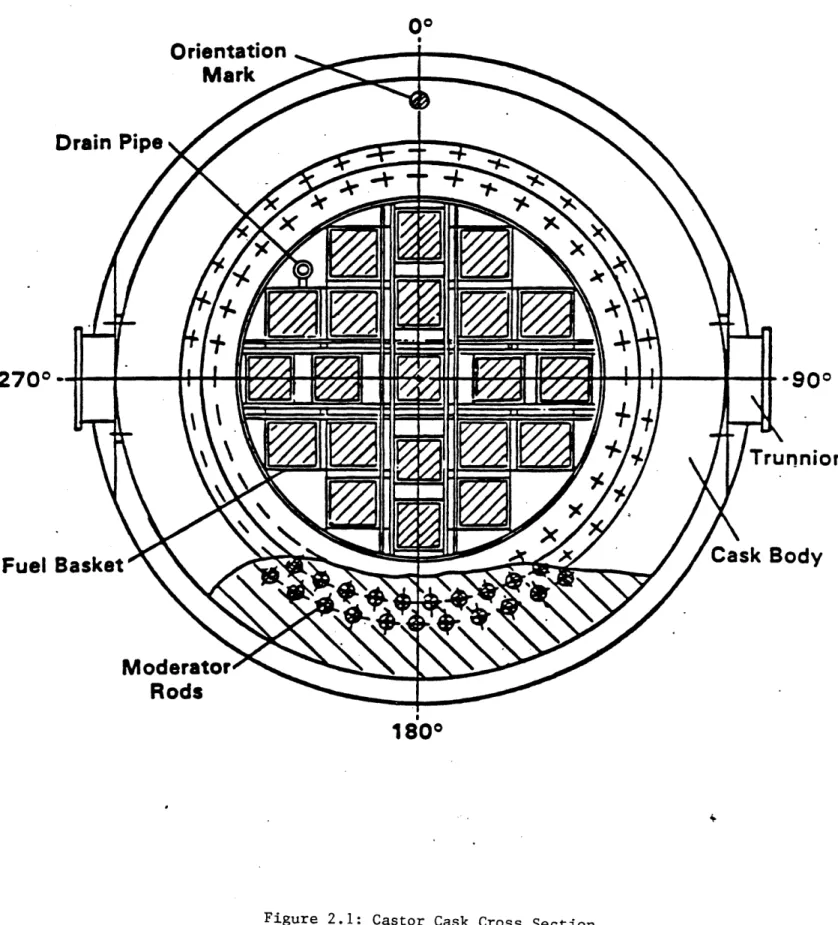
2.1 Castor Cask Cross-Section 14
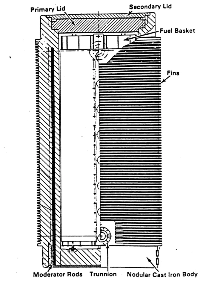
2.2 Castor Cask Dry Storage Cask 15
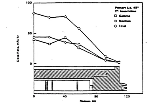
2.3 Castor Cask Dose Rates 16
2.4 Castor Cask Temperature Profiles 17
2.5 Overweight Truck Design Envelope 18
2.6 Heavy Rail Car Design Envelope 20
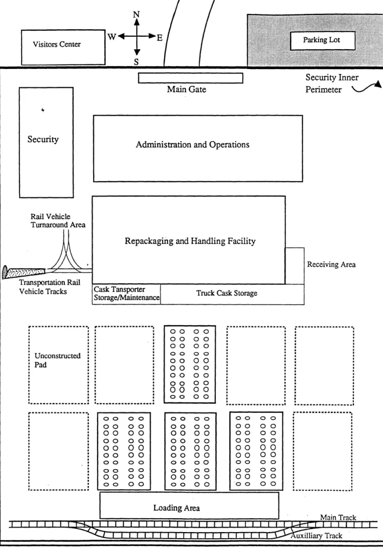
2.7 Repository Site Layout 33
2.8 Primary Facility Layout 34
2.9 Buffer Storage Facility Layout 37
2.10 Cask Transporter 39
2.11 Repackaging and Handling Facility Overview 43
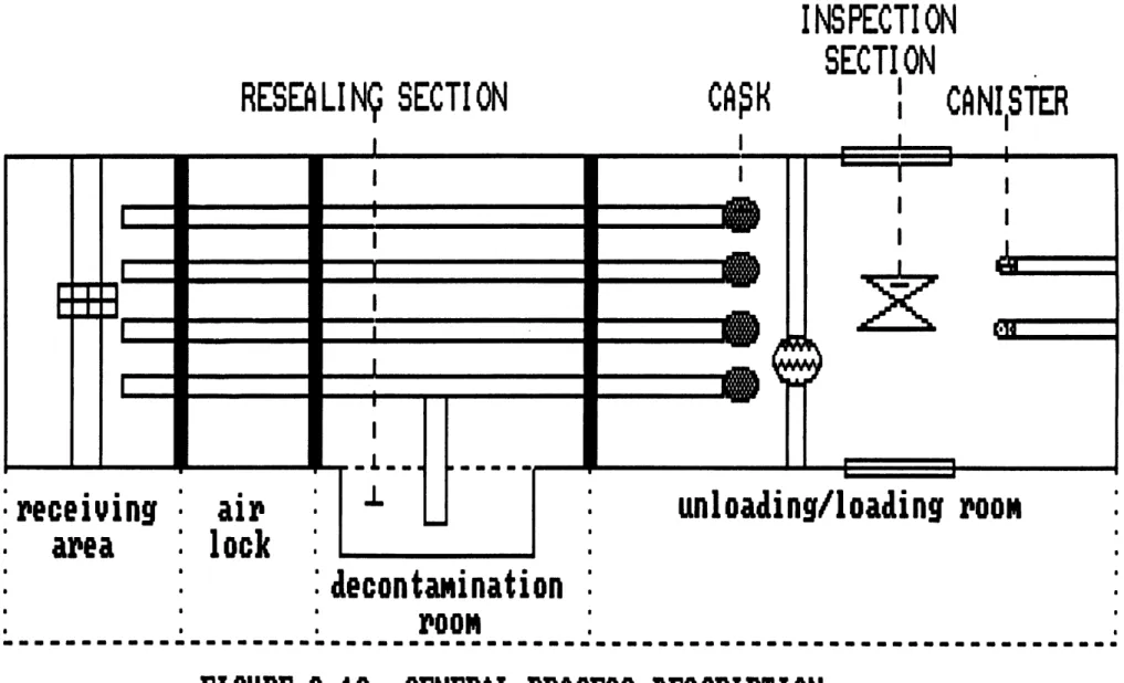
2.12 General Process Description 45
2.13 General Cask Unloading/Loading Design Description 48
2.14 Schematic Representation of Unloading/Loading Room 51
Equipment
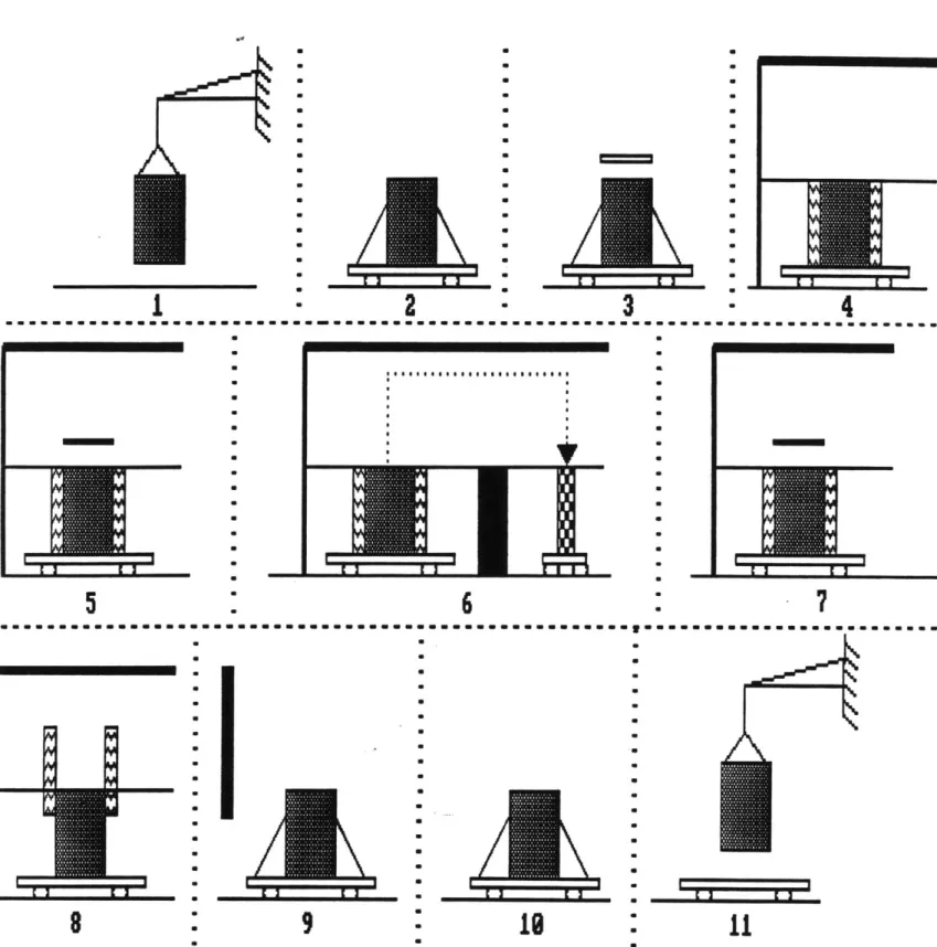
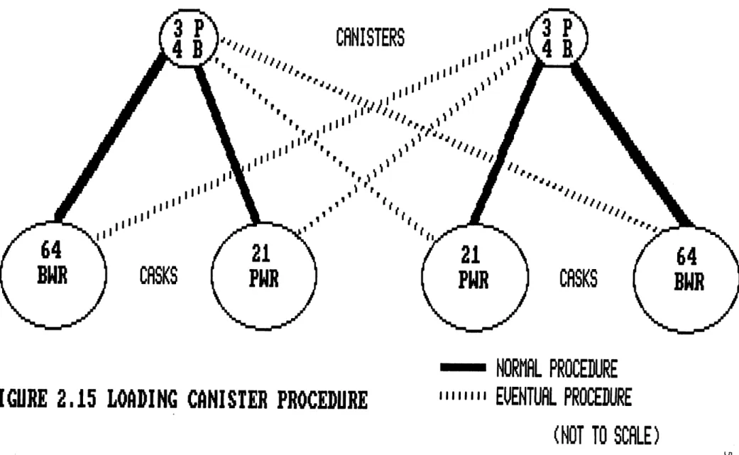
2.15 Loading Canister Procedure 56
2.16 Repository Specific Disposal Canister 57
2.17 Canister Sealing Cell 60
2.18 Welding and Backfilling/Leak Testing Stations 62
2.19 Canister-Carrying Rail Car 64
2.20 Decontamination Cell 68
2.21 Schematic Lag Storage Room Description 71
2.22 Lag Storage Heat Removal Principle 72
2.23 Safety Canister Hook Design 74
2.24 Corridor Sequence Operation 75
2.25 Canister Emplacement Sequence Operation 76
2.26 Emplacement Cask Loading Cell 78
2.27 Canister Downender 79
2.28 Emplacement Cask Loading Operations Sequence 81 3.2-1 Spent Fuel Thermal Source Up to 100,000 Year Cooling Time 100
3.2-2 Toxicity of Nuclear Waste Over Time (Relative to that of Average Mineral Ores of Toxic Elements) Compared to Times
of Social or Geologic Significance
3.2-3 Spent Fuel Container Configurations 106
3.2-4 Unit Cell for Calculation of Repository Pitch for a 107 57 kw/acre Areal Thermal Loading
3.2-5 Effective Spent Fuel Thermal Conductivity 109 3.2-6 Thermal Profiles for Horizontal Emplacement 110
57 kw/acre, 25 m pitch, 2200 watts/ canister
3.3-1 Location of Yucca Mountain Site in Southern Nevada 123 3.3-2 Physiographic Features of Yucca Mountain 124
3.3-3 North-South Stratigraphic Correlation Between 126
Selected Drillholes at Yucca Mountain
3.3-3b Index Map for Selected Drillholes 127
3.3-4 Petrographic Textural Percentages: Topopah Springs Member 128 3.3-5 Usable Portion of the Primary Area and Expansion Areas 131 3.3-6 Cross Section of Emplacement Rooms 136
3.3-7 Plan View of the Repository 138
3.4-1b Rear View of Canister Transportation/Emplacement Vehicle 153
3.4-2a Emplacement Cask 158
3.4-2b Emplacement Cask Cross-Section 158
3.4-3 Temporary Shield Door 161
3.4-4 Cask Alignment System 162
3.4-5a Canister Pickup from Repackaging Facility 165
3.4-5b Transportation/Emplacement Vehicle Travels Down the 165
Repository Entrance Ramp at 1.2% Grade
3.4-5c Emplacement Cask Coupling with Temporary Shield Door 165 3.4-5d Canister Emplacement into Borehole 165
3.4-6 Tunnel and Borehole Backfilling Procedure 167
4.1 Paths of Interest to the Yucca Mountain Project (Paths 1, 181 2, 5a, 6a, 9a)
4.2 Calling Hierarchy of Subroutines in the WADCOM II Model 183
5.1 Schematic of the Repository Design Highlights 204
This report presents a conceptual design for a High Level Waste disposal system for fuel discharged by U.S. commercial power reactors, using the
Yucca Mountain repository site recently designated by federal legislation. It represents the results of approximately 2000 person-hours of work by students enrolled in the combined undergraduate and graduate design subjects
22.033/22.33 of the M.I.T. Nuclear Engineering Department during Spring Term 1988.
Principal features of the resulting conceptual design include
- use of unit trains (including piggyback cars for truck cask transporters where required) for periodic (once every ten years at each reactor) removal of old (cooled > 10 yrs.) spent fuel from at-reactor storage facilities
- buffer storage at the repository site using dual purpose transportation/storage casks of the CASTOR V/21 type
- repackaging of the spent fuel from the dual purpose
transportation/storage casks directly into special-alloy disposal canisters as intact fuel assemblies, without rod consolidation
- emplacement into a repository of modular design having a maximum total capacity of 150,000 MT and an annual handling capability of 4000 MT/yr
- use of excavation techniques that minimize disturbance, both mechanical and chemical, to the geologic environment
- Incoloy 825 waste canisters arrayed to provide 57 kW/acre thermal loading optimized to the projected inventories
- include a unit rail mounted vehicle for both the transportation and emplacement of the canister from the surface facilities to the underground repository
- cost-effectiveness of the Yucca Mountain Site Criteria was studied via: a computer model, "WADCOM-II - Waste Disposal Cost Model II"; and an independent cost evaluation by the members of the design team. The total system cost (in constant 1988 dollars) was 1.9 billion dollars by WADCOM-II, and 5.3 billion dollars from the independent cost evaluation, resulting in a levelized disposal cost of 0.2 mills/kW-hr by WADCOM-II and 0.55 mills/kW-hr by the independent cost
evaluation.
The work reported herein is solely that of the (three) undergraduate and (six)
graduate students identified on the title page. However, significant contributions were also made by several individuals consulted in the course of this effort, the following in
particular: Prof. R.G. Ballinger and R.K. Lester of the M.I.T. Nuclear Engineering Department; Dwight Shelor of the Office of Civilian Radioactive Waste Management Headquarters in Washington, D.C.; Spyridon Tzeros of Battelle Columbus Laboratories from whom WADCOM-II was obtained; Rachel Morton, a computer consultant for the M.I.T. Nuclear Engineering Department, who helped get WADCOM-II running; Anne
Hudson of the Nuclear Engineering Department for her tremendous secretarial support; and Prof. M.J. Driscoll of the Nuclear Engineering Department for his many efforts in assisting
with the development and completion of this report.
The efforts of Steve Boerigter, William Hollaway, and Scott Simonson were
performed under appointment to the Nuclear Engineering, Health Physics, and Radioactive Waste Management Fellowship Program administered by Oak Ridge Associated
Universities for the U.S. Department of Energy.
CHAPTER1 INTRODUCTION
1.1 Foreword
Each year the combined undergraduate/graduate design subjects in the Nuclear Engineering Department at MIT are assigned a comprehensive systems design project relevant to contemporary issues. This spring (1988) the task of developing and evaluating a conceptual design for a HLW repository was considered to be particuarly timely in view of the recent designation by the federal government of Yucca Mountain, Nevada, as the sole site for the U.S. repository. An even more compelling motivation was the fact that in the view of the general public, the presumed lack of a means to dispose of spent nuclear fuel is the most important barrier to further (or even continued) use of nuclear power.
In view of the wide-ranging scope of the problem, considerable attention was paid at the outset to negotiation of a well-defined set of assumptions and boundary conditions on the assignment at hand. The results are summarized in Table 1.1. Location, customers served, and time frame are the most important entries. While overall cost optimization is, as usual, the principal goal, it is tempered in the present instance by the hard-to--quantify considerations of risk aversion by the public, and an underlying faith in simplification of
design and operations as a means towards realization of a successful concept. Time constraints also limited the degree of optimization achievable.
Table 1.1. Ground Rules
Location: Yucca Mountain, Nevada Target Date for Operation: 2005
Steady State Handling Capability: 4000 MT/yr Total Capacity 2 70,000 MT
No special effort to insure retrievability
No requirement for an independently located MRS
All applicable NRC, EPA, DOT, and other regulations are to be met
Design focus on spent LWR fuel assemblies (PWR, BWR); but vitrified wastes (both commercial and defense) and advanced reactor (LMR, MHTGR) fuel or reprocessed wastes are also acceptable
Concurrent use of repository for defense HLW was not examined, but was not specifically precluded
Goal was to minimize overall levelized cost of waste disposal to nuclear-generated electricity (mills/kwhre) ratio
To the extent practicable, the waste container and overpack are to be less hazardous than the contained waste
1.2 Background
The problems associated with waste disposal from commercial nuclear power reactors have become an issue of concern for several reasons. First, radioactive wastes are
extremely hazardous and present a potential danger for many thousands of years. Second, high level waste in the form of spent nuclear fuel assemblies have been piling up at reactor sites across the country for over two decades. Third, the storage capacity designed and constructed at these facilities is rapidly being exhausted. Finally, neither the federal government nor any other body had set up a mechanism to address and solve the problems of high level radioactive wastes until only six years ago. In 1982, the President of the United States signed into law the Nuclear Waste Policy Act of 1982. The Act specified that high level radioactive wastes would be disposed of in underground repositories. The first site was to be selected by a process which narrowed a list of nine original sites first down to five, then three, and finally one site. The sites were reduced down to three sites partially by the use of a multi-attribute utility analysis to assess the problem. In going from three sites down to the final site, however, the process became embroiled in debate and slowed to a standstill. To remedy this, the Congress of the United States passed an amendment to the original Nuclear Waste Policy Act which made the Yucca Mountain Tuff site in Nevada the first choice for the site of the nation's first high level waste repository, unless evidence precluding this choice is found. Addressing the problems related to radioactive waste disposal in the light of a confirmed repository site is the motivation for this project, which uses the Yucca Mountain site as the basis for a "Design of a High Level Waste Repository System for the United States."
1.3 Report Organization
The effort reported here quite naturally falls under two major catagories:
above-ground and below-ground, from both a technical and an economic standpoint (e.g., overall cost is roughly evenly divided between these activities).
Chapter 2 is devoted to surface facilities and operations, including at-reactor
operations, transportation, and at-repository surface facilities (buffer storage, repackaging, and canister handling.)
Chapter 3 focuses on the underground repository, including engineered barriers, geological characterization, repository construction, and emplacement operations.
Since the objective of this effort was to devise a comprehensive, cost-effective overall system, Chapter 4 addresses system economics, with heavy reliance on the WADCOM-II computer program, in addition to independently-derived subsystem costs estimated by the members of the design team.
Finally, Chapter 5 summarizes the principal findings of the report and identifies priority items for future work.
1.4 Repository Startup Date
The planned date for beginning repository operation is in the year 2005, with spent fuel initially being accepted beginning in the year 2003. These dates are based on
conservative estimates of the time required for: geologic testing; system design; system licensing; politics and congressional approval; construction; and pre-operational testing. The time estimates for each of these items are given in the table below:
Geologic Testing
and 5 years
System Des ign
Licensing - NRC 3 years
Politics and Congressional Approval 2 years
Construction 6 years
Pre-Operational Testing 1 year
TOTAL = 17 years
Thus, the repository opening date is conservatively estimated to be in 2005, and in order to have a sufficient supply of spent fuel to begin operations, the surface facility will begin transporting and storing spent fuel starting in 2003.
If the repository opening is delayed beyond 2005, the surface facility will still begin accepting fuel starting in 2003, and the surface facility buffer storage capacity will be increased as needed. If the surface facility spent fuel storage capacity is projected to exceed 10,000 MTU of spent fuel, a license submittal will be made to the NRC to license the facility as a federal interim storage facility before any spent fuel in excess of 10,000 MTU will be accepted.
CHAPTER 2
SURFACE FACILITIES AND OPERATIONS
2.1 Introduction
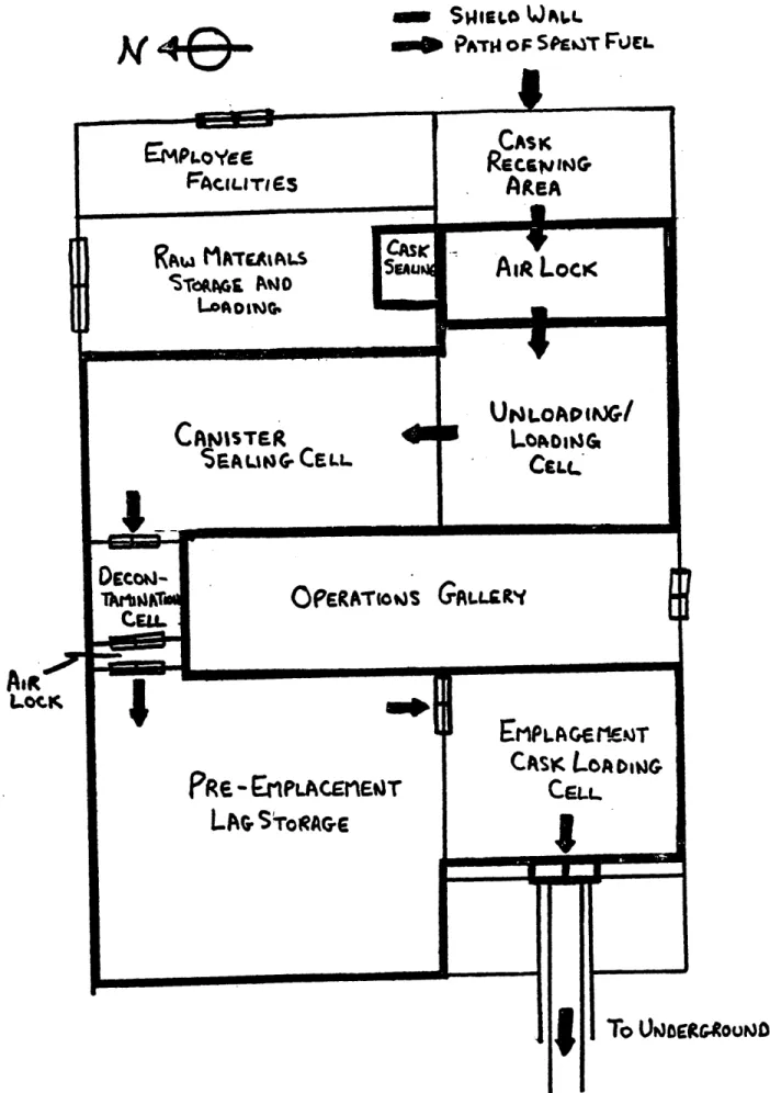
The Surface Facilities and Operations chapter encompasses all of the activities from the reactor, where the spent fuel is picked up, to the underground repository interface, where the sealed disposal canisters are transferred to the underground repository facility. This chapter discusses spent fuel handling, transportation, storage, and finally repackaging into repository specific disposal canisters.
The following is a synopsis of the reactor to repository system design. The system uses nodular cast iron Castor V/21 type spent fuel casks for both transportation to and storage at the repository. The system does not include a Monitored Retrievable Storage (MRS) facility. Instead, handling and repackaging operations are done at the repository site, and a small buffer storage facility is included at the repository surface.
Transportation from the reactor to the repository is by dedicated unit trains, which will pick up a full load of spent fuel from any given reactor site once every ten years. The unit trains will be purchased as part of the overall repository system, and therefore their cost is explicitly included in the estimated costs of the repository system design. The repackaging operation at the repository site deals entirely with intact spent fuel. No rod consolidation is done, and the intact fuel assemblies are loaded directly into the disposal canisters. The entire reactor to repository system is designed to process an average of 4,000 MTU of spent fuel per year, using only fuel which has been cooled out of reactor for ten years or more.
Several critical decisions were made during the design process in order to come up with this reference system design. The most important of these decisions are discussed in the following paragraphs.
The Dual Purpose Cask Decision
The reference system uses a nodular cast iron cask for both transportation from the reactor to the repository, and buffer storage at the repository site. This design concept was selected to limit the amount of required handling of the spent fuel in order to limit
radiation exposures, accidental release probabilities, and handling costs. The major assumption of this decision was that a suitable dual purpose storage and transportation cask will be available by the time the system begins accepting spent fuel in 2003. The reference cask design selected is the Castor V/21 cask made by GNS of the Federal
Republic of Germany. Although this cask has not been licensed as a dual purpose cask in the United States, it is licensed for spent fuel storage in the United States, and similar GNS casks are licensed and routinely used for spent fuel transportation in Europe.
The Monitored Retrievable Storage (MRS) Decision
The system design does not include an independently located MRS facility. The decision to not include an MRS was made for several reasons. First and foremost, all of the handling and repackaging operations done at an MRS can just as easily be done at a
facility at the repository site. Second, it was viewed as beneficial to have the repackaging operation co-located with the repository, which leaves no potential for a transportation bottleneck that would leave repackaged fuel stranded and unable to be placed in the underground repository. Third, the moderately sized (4,000 MTU maximum capacity) buffer storage facility at the repository site provides the same system flexibility as the MRS storage facility, without requiring a substantially larger storage facility (MRS capacity is 15,000 MTU) located somewhere else in the country. Finally, performing the repackaging at the repository site, instead of at an independently located MRS facility, means that the Department of Energy and the United States Congress will not be required to wade through another long and complicated process to site another domestic high level radioactive waste facility.
The Unit Train Decision
The reference system design includes dedicated unit trains that will pick up a full trainload of spent fuel from one reactor at a time, and pick up at each domestic reactor will be done once every ten years. This system design was selected for several reasons. First, unit train shipments are much easier to monitor and protect than are a larger number of smaller shipments by regular cargo trains. Second, using large unit trains to visit each reactor infrequently reduces the total number of shipments made, and therefore the number and frequency of shipments passing through specific states and geographic regions of the country. This is a great public policy and relations advantage of the design. Finally, visiting each reactor only once every ten years greatly reduces the inconvenience to power operations at the reactor.
The System Throughput Decision
It was decided that the entire reactor to repository system will process 4,000 MTU of spent fuel per year, and that only spent fuel that has been cooled out of reactor for ten years or more will be accepted. The throughput rate of 4,000 MTU per year was selected
because it is the best estimate of the eventual steady-state annual spent fuel discharge rate from all of the power reactors in the United States. The system design could easily be modified for a higher throughput rate, but it is impractical to receive more spent fuel per year than is being generated, which would eventually lead to a time when the repository would have to shut down for a period of years in order to wait for more spent fuel to be generated. With an annual throughput rate of 4,000 MTU per year and a 2003 initial spent fuel acceptance date, it was found that if a policy of "oldest fuel first" is used when picking up spent fuel from the reactors, then the criteria of accepting only fuel cooled out of reactor for ten years or more follows naturally, and places no unnecessary constraints anywhere in the system.
The Consolidation Decision
A decision was made to dispose of the spent fuel as intact spent fuel assemblies, and that no rod consolidation will be done. This critical decision was made after several long discussions in which the advantages and disadvantages of rod consolidation were listed and compared. There are several disadvantages to performing rod consolidation. First, rod consolidation requires a high degree of technical sophistication: the equipment is in a harsh radiation environment; robotics are required which are beyond the present state of the art;
and elaborate computer systems and artificial intelligence that would be at the very cutting edge of today's technology are required. Second, the rod consolidation process is arguably the most dangerous step in the entire waste disposal process: it has the greatest potential for releases of radioactivity of any operation in the entire system; the potential exists for in-cell fires due to the ignition of pyrophoric zirconium fines generated in the process; and there is the problem of criticality any time there is a large number of unconstrained fuel assemblies. Third, the rod consolidation process has the potential to be a severe system bottleneck: the technology of rod consolidation is untested and the current evolutionary design process will not produce a testable system for close to ten years; if the rod
consolidation system breaks down it is on the critical flow path and will force the whole system to shut down; and the rod consolidation equipment will be optimized for one type of waste package and any package changes may force a extensive redesign of the equipment. The potental advantages of rod consolidation are few, but may be quite important. First, if heat transfer within the canister is a problem, the consolidated fuel provides a better heat transfer mechanism than does intact fuel. This possibility was investigated (see
3.2.2.3), and it was found that peak canister temperatures were not a problem for either consolidated or intact spent fuel. Second, intact spent fuel may present a criticality problem due to its highly reactive geometry as opposed to the highly undermoderated
geometry of consolidated spent fuel. For the small amount of spent fuel contained in each of the reference design canisters, criticality was judged not to be a problem. The final possible advantage of rod consolidation is the potential savings in disposal cost due to the use of fewer canisters. This was investigated, and it was found that the additional number of canisters required in combination with the relatively low cost of the design disposal canisters resulted in no substantial cost savings for this design, particularly when the additional cost of design, fabrication, and operation of the rod consolidation equipment is considered. In summary, the clear disadvantages of rod consolidation for this design were viewed to far outweigh the somewhat nebulous advantages, and therefore rod consolidation was not included in the system design.
2.2 At-Reactor Operations 2.2.1 Introduction
The at-reactor operations consist of loading the spent fuel assemblies into a transport cask and then loading the cask onto a train or truck for transportation. A "unit train" concept is used because it was determined to be the safest and most efficient mode of transportation to the repository. The facilities at the reactors that are used for the preparation of the spent fuel are supplied by the repository. By supplying the necessary extra equipment to the reactors, the at-reactor operations are kept as inexpensive and uniform as possible.
2.2.2 Unit Train Concept
The transportation of spent nuclear fuel can be accomplished through the use of trucks, railroads, and/or barges. In assessing the optimal modal mix for the present
situation, four broad areas need to be considered: public acceptance, safety, environmental impact, and economics. The design philosophy of the transportation phase of the waste disposal system has been to make decisions based on these criteria in this order of priority. Because the cost of transporting nuclear wastes is relatively small compared to the other phases of the disposal process, and because transportation involves the greatest degree of contact with the general public, it is prudent to choose the mode of transport which is safest and most acceptable to the public even if this results in an increased cost. The modal mix which best fits this philosophy is the unit train concept, with truck and barge transport to be used only cases where rail access to a site can not realistically be achieved. Special dedicated trains will be set up specifically for this purpose which will allow them to run with less frequency and with greater ease of coordination and security control. More details concerning regulations, operations, routing, shipment frequency, and security can be found in Section 2.3.3.
2.2.3 Storage/Transportation Cask
Two types of transport casks will be used in the repository operations. Reactors with rail spurs will use the Castor-V/21 cask. Since the Castor cask cannot be transported by truck, reactors without rail spurs will be forced to use standard truck casks. The advantage of the Castor-V/21 spent fuel cask is its dual purpose nature; this cask can be used as a storage cask as well as a transport cask. Although the Castor-V/21 is presently awaiting transportation licensing, the cask will most likely have its license by the time the
repository begins collecting spent fuel.
Repository operations will be simplified considerably by using a transport cask that doubles as a storage cask. The Castor cask would save the time and expense of reloading incoming spent fuel from transport casks to storage casks. Although several other cask vendors are also awaiting transportation licensing of their casks, the Castor cask was chosen because of the abundance of available technical data and the decision of Surry Power Station to purchase five Castor-V/21 casks for their new dry storage facility.
Designed by Gelleschaft fur Nuclear Service of the Federal Republic of Germany, the Castor-V/21 cask is constructed from nodular cast iron. With an outside diameter of 8 feet and an axial length of 15 feet, the cask is designed to hold 45 intact BWR fuel assemblies or 21 intact PWR assemblies with enrichments less than 3.5 percent (Figs. 2.1 and 2.2). The assemblies must be aged more than 5 years, have burnups less than 35,000 MWD/MT, and have decay power less than 1 kW per PWR assembly. These limitations may require the use of an alternative cask with higher specifications in the future for fuels with higher burnups. The cask's neutron shielding is accomplished by moderator rods that are placed into axially drilled holes in the iron wall. The gamma shielding of the cast iron lowers the dose rate to approximately 50 mrem/hr on the sides although there is a higher dose on the top due to the lighter shielding (Figure 2.3). This massive shielding explains the cask's unloaded weight of approximately 100 tonnes. Two stainless steel lids with metallic seals
O*
2700-Fuel Basket
.900
Trunnion
Cask Body
4.Fuel Basket
_
Fins
Nodular Cast iron Body
0 100 200 300 400 500
T. eC
CASTOR-V/21 Axial Temperature Profiles
120 80 40 0 40 80 120 Radius. cm
CASTOR-V/21 Radial Temperature Profiles
Figure 2.3: Castor Cask Dose Rates
Soo 400 300 200 100 E P.' T. -C
detection circuit is also included to facilitate inspections and monitoring.
The truck casks used by the reactors without rail spurs are much smaller than the Castor cask. These casks are available in sizes large enough to carry almost 10 tonnes of spent fuel. A typical example is the CNS 14-190H Transport Cask, marketed by
Chem-Nuclear Systems, Inc. This large volume Type A cask accepts up to a 20,000 pound (9.1 tonne) payload.
2.2.4 Facilities and Operations
Every ten years, a shiptment of thirty empty casks is delivered to a reactor facility. The facility is responsible for loading the oldest spur. Once at the rail spur, the repository transportation staff oversees the loading of the casks onto the unit train. Each unit train carries a mobile crane for this purpose. Plants that do nto have access to nearby rail spurs load their spent fuel into smaller truck casks and transport them to their assigned location by truck. The trailers and casks are then loaded onto the train together as in a
conventional "piggyback" operation and transported to the repository site (see Fig. 2.5). The reactors that have access to a rail spur utilize a larger cask that is placed directly on a rail car (see Fig. 2.6) and are the cask transporter that is supplied by the repository. The task of loading the casks onto the unit train is the repository's
responsibility and is done with the aid of the crane on the unit train.
The process of loading the casks with the spent fuel assemblies is a relatively simple one. The cylindrical casks arrive at the reactor site unassembled (i.e., the lid will not be
attached) and are immersed into the spent fuel pool. The fuel is placed into the cask, the water is drained out of the cask and the lid is welded on. The cask is sealed and is checked for leaks.
2 E 0 50 100 150 Dose Rats, mR/hr 100 PO r Lid. 21 Aawwmsee o Gemm*. o NeOuMa so- 50-0 40 so 120
GAMNA AND NEUTRON DOSE RATES ON CASTOR-V/21
400 Side. 45* 21 Assemt 300 - O Gamm E -Nutro 0 Total 200 100 -200
GAMfA AND NEUTRON DOSE RATES ON CASTOR-V/21 SIDE
Figure 2.4: Castor Cask Temperature Profiles
of
oo
1.2
m
(4'1")-+
<-
1.2 m (4'1")
P!-3
3
m-->
I
(11
')
5000 kg
(11,000 Ibs)
1.2 m (4'1")-9.1 m (30')
21,400 kg
47,000 Ibs)
0 0
1.2 m
(401
01
21,400 kg (47,000 Ibs)F/(7
5-Overweight Truck Design Envelope
-2.2.5 Flat Car Design
There are two types of rail cars that will be used in the transportation of the casks to the repository site. For the reactors with access to a rail spur, a flat-car capable of
transporting the Castor cask will be used. For the reactors without rail access, a flat-car capable of carrying truck trailers in the conventional "piggy-back" style will be used.
The rail car designed for carrying the larger Castor cask is capable of holding as much as 200 tonnes of gross vehicle weight. The rail car is 27 m (90 ft) in length and has double trucks at each end of the rail car (see Fig. 2.6).
The rail car that will be used in the "piggy-back" operation is of a conventional type. The truck trailer, however, is an overweight design and will require overweight permits. The permits are not difficult to obtain and should not be the limiting factor as long as the weight restriction of 50 tonnes gross vehicle weight is followed. This weight will be
distributed over seven axles (see figure 2.5) and is in common usage today. 2.2.6 Reactors Without Rail Spurs
Forty-two commercial nuclear reactor sites in the United States do not currently have rail access [2-1]. In addition, some rail right-of-ways will require upgrading to handle overweight rail casks. To the greatest extent possible, these sites will have rail spurs laid or upgrading done so that use can be made of more economical, safer, and more publicly acceptable rail transport.
In the cases where this can not be accomplished, two options are available. If the site is accessible by ocean waterways, barge transport can be used to convey rail casks to the nearest railroad branch. Alternatively, fuel can be placed in truck casks and transported by highway routes to a railroad branch, in which case the trucks will be transported piggy-back style to the repository site as part of the unit train.
(VkV;vAWAAAAA AA A A AA A AAA1A AA AA A 5'6")-.-[ 1.7 20 n (65') 100,000 kg (220,000
lbs)
100,000 kg (220,000 lbs)2.2.7 Off-Normal Events
During the process of transporting and loading the casks, certain problems could arise. There is always the chance that the cask could be dropped when being transported from the fuel pool to the storage pad since the cask is lifted off the ground. If the cask is
dropped, it will immediately be inspected for leaks and cracks in the weld. If any are detected, the cask will be resealed. If the cask is beyond repair, the fuel assemblies will be reloaded into a different cask and sealed in the same manner as before.
If, immediately after a cask has been welded shut, a leak is detected, the cask must be opened and rewelded shut before it can be transported. The casks are routinely monitored for any leaks that may develop throughout the operation.
Since the cask serves the dual purpose of both a storage and transportation medium, no significant problems arise if a unit train fails to pick up the casks. The storage pads at the reactors have enough space to store the casks until the behind-schedule train can be serviced and/or replaced.
2.3 Transportation
2.3.1 Introduction
Transportation is an integral and essential part of the projected waste management system. The United States has a long history of transporting radioactive material. Commercial spent fuel has been shipped for over 20 years and high-level waste from
defense activities for an even longer period. These shipments have been conducted without any accidents causing death or environmental damage due to the radiological nature of the cargo. The DOE is taking measures to ensure that this safety record continues. An
extensive program is under way to develop equipment and procedures that can accommodate the expected increase in the number of shipments when Nuclear Waste Policy Act (NWPA) facilities begin operating. Under the NWPA, the Office of Civilian Radioactive Waste Management (OCRWM) will accept commercial waste at reactor sites or point of origin for transport to the repository. Spent fuel shipments will be in
compliance with all applicable Federal regulations and OCRWM procedures in effect at the time of transfer to the repository. In addition, State, Tribal, and local requirements that
are consistent with Federal Law will be followed. In implementing the DOE's mandate under the NWPA, the OCRWM will develop and operate a transportation system to move waste from the commercial reactors where it is generated and currently stored to the
repository at Yucca Mountain, Nevada. This system requires development of the physical equipment and transportation services to transport the waste as well as an institutional framework that will act to facilitate the effective development and operation of the system.
The projected physical transportation system will consist of shipping casks, carriage equipment, and associated ancillary equipment. The services required will include the carriage of the fuel by commercial transport companies, the maintenance of the casks and other equipment, and the training of system operators such as drivers, maintenance personnel, and inspectors. In accordance with the NWPA, the OCRWM "... shall utilize
by contract private industry to the fullest extent possible..." to develop and operate this system.
A successful transportation system must not only be safe and efficient but also widely acceptable. To achieve the necessary public understanding, a number of questions and issues regarding the establishment and operation of the transportation system must be addressed. Since the transportation phase of the waste disposal system involves the greatest degree of contact with the public, it is here that steps must be taken to minimize any accidents or problems that occur, and to prevent such complications to the greatest extent possible. An extensive public relations plan that points out these safety measures and emphasizes the excellent safety record of radioactive materials transport relative to other dangerous materials will be an important part of the transportation system. While public policy is complicated by the differing interests of the parties involved, it is an important key to program implementation.
2.3.2 At-Reactor Operations
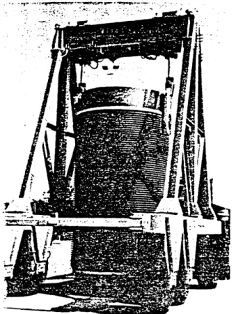
At each reactor, there is a "reactor-repository interface team" of approximately five people that is responsible for supervising the preparation and loading of the spent fuel assemblies into the transportation casks. When the transportation casks are delivered to the reactor site, a cask transporter will also be unloaded to facilitate the cask movements. The casks are then transported to the spent fuel pools and loaded with the oldest fuel assemblies first. The loading process will not require a significant amount of extra equipment at the reactor since the cask loading operation is similar to the loading of the
assemblies into the spent fuel pool. Once the assemblies have been loaded, the cask is backfilled, sealed, leak checked, and transported to the holding pad to await
transportation.
Although each reactor may have its own special needs, the basic operation will follow one of two paths. If the reactor does not have a nearby rail spur or access to a rail line,
then the reactor is responsible for transporting the truck casks from the designated drop-off point to the reactor site. If the reactor has access to a local rail spur, then the full size casks and cask transporter are delivered to the holding pad at the reactor.
The casks are transported to the spent fuel pools and loaded with the spent fuel. The process involves the lifting of the cask and placing it in the pool using a crane which has been upgraded to lift the cask. Most reactors' cranes are designed to lift maximum weights comparable to that of fuel assemblies. The repository has the responsibility of upgrading the cranes to accommodate the extra weight of the transportation casks if the reactor has a rail spur and uses the larger cask.
When the casks are loaded with the spent fuel assemblies, the oldest fuel is loaded first for safety reasons. During the initial operational period, it is a good idea to transport the fuel that is not as hot in case some unforeseen problems arise. There is also the
common sense reason that the first in should be the first out. This method prevents the accumulation of extremely old fuel assemblies in the spent fuel pools. Once the
transportation system has been completely tested and shown to be safe, the repository, if necessary, can dictate what heat load of spent fuel should be transported to the repository. By doing so, the repository is able to utilize as much of the underground space as efficiently as possible.
2.3.3 Reactor to Repository Transport 2.3.3.1 Regulations
Inspection and enforcement activities for the transportation of radioactive materials are shared by Federal and State agencies. The responsibilities of various agencies are reviewed below.
The Nuclear Regulatory Commission (NRC) maintains an active inspection and enforcement program to ensure that its regulations and control procedures are met by
licensees. The NRC is responsible for review of: procedures for preparing empty casks for transportation, procedures for loading shipping casks on transport vehicles,
cask-maintenance programs (periodic cask testing, inspection, and adherence to replacement schedules), physical protection plans and procedures, and radiation
monitoring. Enforcement mechanisms for violations of NRC requirements include written citations and monetary penalties.
The Department of Transportation (DOT) inspects radioactive waste shipments to monitor compliance with regulatory requirements. DOT inspectors are provided by the Office of Research and Special Programs Administration, the Federal Highway
Administration, and the Federal Railroad Administration. Inspections monitor compliance with in areas such as package marking and labeling, placarding, shipping papers, and radiation dose rates. In addition, inspections vehicle safety and route plans, track safety, power and equipment, operating practices, and signal and train controls. There are written citations and monetary penalties in use to enforce DOT requirements.
The Department of Energy (DOE) is also responsible for the inspection of casks and transportation vehicles used in the shipment of radioactive waste. The DOE reviews areas such as: preparation of casks for transport, vehicle loading and safety, marking and
labeling, placarding, physical protection plans, and radiation emissions from the casks. The enforcement procedures used by the DOE are specified in contractor agreements, and include the suspension and termination of contracts as penalties for noncompliance.
States wishing to implement and enforce Federal regulations governing the transportation of radioactive materials are required to train and certify personnel and conduct State inspection and enforcement activities in a manner consistent with Federally established procedures. The Motor Carrier Safety Assistance Program is provided to States to assist in the development of safety regulations for commercial motor vehicles.
The Federal Railroad Administration supports programs to assist in the development of regulations for rail transport.
2.3.3.2 Transportation Operations
All shipment operations to be performed by transportation service contractors are included in a Transportation Operations Procedure Manual. This manual standardizes procedures across the transportation system to insure smooth operation and compliance with governing regulations.
Operational Scheduling is the first stage of the transportation process. A precise schedule of activities is necessary to insure that all events take place as required without delays or interruption. The first event in this category is the arrival of the casks and
transporter at the reactor site and the loading of the shipment as described in Section 2.2.4. Shipment checkout procedures are required to insure compliance with all relevant regulations prior to the dispatch of the shipment. After a physical inspection of the shipment and equipment, shipping papers and title must be prepared and accepted. After the actual dispatch of the shipment, notification of appropriate authorities must take place.
While the shipment is in transit, continuous attention to routing (as described in Section 2.3.3.3) and security procedures (as described in Section 2.3.3.5) must be maintained. A special truck or rail car will be travelling at the front of the shipment
convoy to monitor upcoming road or track conditions and to notify the rest of the convoy as well as the appropriate authorities in the event that emergency procedures need to be
implemented (as described in Section 2.3.3.5).
The final stage of the transportation process, shipment receipt, also requires careful scheduling well in advance to insure the availability of the necessary equipment to transfer the shipment casks to the buffer storage area (as described in Section 2.4.3.4) in an efficient
manner. After a final inspection has taken place, the casks can be unloaded and the decontamination check-out procedure can be completed, at which point release of equipment takes place and the transportation phase has ended for this shipment.
Provision will also be made for scheduled and unscheduled maintenance and repair of the casks and transport equipment, as well as inspections by State and Federal authorities.
2.3.3.3 Highway/Rail/Barge Routing
As discussed in Section 2.2.2, the Unit Train Concept was determined to be the optimal method of waste transportation when safety, economics and public policy are econsidered together. Consequently both highway and barge transport will be us d only in
cases where rail access to a reactor site is not available. In these cases, the routing used will presumably be the most direct route from the reactor to the nearest rail spur, with necessary detours around population centers or possible trouble sites. Since rail
transportation offers fewer routing alternatives than does highway transportation, due to a smaller number of alternate routes and the condition of rail tracks, it will be somewhat easier and less expensive to conduct optimization studies for rail routing. The route planning criteria established by the OCRWM require the selection of rail routes that limit shipping costs and transit times, avoid population centers (where possible), and avoid adverse weather conditions. Within these guidelines, private industry will be utilized to the greatest extent possible to develop and maintain routing plans for each reactor.
2.3.3.4 Shipment Frequency
The average amount of fuel that comes into the repository is 4,000 MTU per year. This number was chosen to keep pace with the reactor output each year. In order to
achieve this rate, a unit train must pickup spent fuel from each of the 126 reactor sites once every ten years. Each unit train has 100 rail cars, 60 that are designed to carry the Castor
casks, and 40 that carry the truck casks. Since each reactor loads 300 MTU into the thirty casks it receives, the unit train is able to visit three reactors at a time. With this
knowledge, a train must make approximately five trips a year between the repository and the reactors in order to deliver 4,OOOMTU per year.
Due to the time involved with unloading, loading and filling the casks, a train is only able to make two trips per year which results in the need for three unit trains. This
estimate is a conservative one and may change as the operations become more familiar to the personnel involved.
2.3.3.5 Security
Federal regulations for the protection of commercial spent fuel shipments from acts of theft and sabotage are specified in 10 CFR 73.37 (NRC), 49 CFR 173.22 (DOT) and DOE
Order No. 5632.2. The actions required under these regulation are summarized below. 1) NRC approval of the route in advance of shipment.
2) The development of specified procedures for coping with circumstances that threaten deliberate damage to the spent fuel shipment.
3) Provision of at least one escort to maintain visual surveillance of the shipment during stops.
4) Use of a commercial center at a designated location to monitor the progress of the shipment.
5) Calls made to the communication center by shipment escorts at least every two hours to relay the status of the shipment.
6) Shipment planning to avoid intermediate stops to the extent possible.
7) Advance arrangement with local law enforcement agencies along the route to assist in their response to and emergency.
8) The use of one escort to accompany a driver in a transport vehicle or the use of a second vehicle occupied by two escorts.
9) The use of some form of vehicle locating device to assist in response in the event of an emergency incident.
10) Inspection before shipment for evidence of sabotage attempts. The utilization of these procedures will help to reduce the possibility of an emergency incident and will facilitate a response in the unlikely event that an emergency arises which cannot be handled by personnel present in the transport convoy. In case such an emergency does arise, assistance will be provided by State and local governments and the Federal Emergency Management Agency.
2.3.4 At-Repository Operations
When the unit train reaches its final destination at the repository in Yucca
Mountain, Nevada, the transportation phase of the operation has ended. Once the train has stopped on the siding near the buffer storage area and the necessary security and
regulatory procedures have been completed, the casks will be transferred to the buffer storage area as described in Section 2.4.3.4.
2.3.5 Public Policy Issues
Public policy issues are extremely important to consider at an early stage in the development of a nuclear waste management program because there already is a great deal of opposition to nuclear power (even if much of it is purely political in nature), and
nuclear wastes are often cited by critics as a serious problem that must be dealt with before any more nuclear plants are built. Since the transportation phase of waste disposal
involves the greatest degree of contact with the general public, it is especially important to include an educational program as part of the repository design report. An examination of the history of radioactive materials transportation shows an excellent safety record. In shipping about 5000 spent fuel elements over the past 20 years, there have been only two transportation accidents of any kind and none involved any release of radiation or injury to the public [2-2]. The main reason for this is the high standards set for the design of
transportation casks as described in Section 2.2.3. The worst type of accident that could occur during transportation is considered to be a terrorist attack with explosives. A test
performed at Sandia National Laboratories simulated such an attack on a cask containing a fuel bundle [2-3]. They found that the amount of radioactive material released under those circumstances would cause no immediate injuries or fatalities and at most one cancer
fatality many years later. In another set of tests, casks were crashed into a cement wall at 80 mph, hit by a 120 ton locomotive at 80 mph, dropped to the earth from a height of 2000 feet, and submitted to fire conditions six times as severe as required by regulations; in each of these cases, the casks survived without severe damage or release of significant
radioactivity [2-4]. These facts are a good illustration of the principle that risk is easier to reduce when danger is concentrated. The amount of spent fuel transported in the United
States is minuscule when compared to the huge volumes of other types of hazardous wastes produced every year such as 9 million tons of chlorine, 16 million tons of ammonia, and 32 million tons of sulfuric acid. It would obviously be impossible to transport this amount of
material in spent fuel transport casks. In fact, no other hazardous materials are required by regulation to be shipped in accident-resistant containers [2-5]. This explains why
accidents involved with gasoline transport caused 480 deaths from 1976-1980 [2-6], and why coal transport causes between 700 and 1300 public fatalities per year [2-7]. When presented with this information, many critics will say that there is still no justification for adding to the already existing dangers with more nuclear power. But it is important to note that replacing some of the large percentage of US energy generated by coal with nuclear power, those dangers can be reduced. A 1000 MW coal plant produces solid wastes at the rate of 30 pounds per second [2-8]. They include 19 toxic metals (such as arsenic), carcinogens (such as benzopyrene), mutagens, and are more radioactive than the routine emissions of a nuclear plant. Even worse health hazards are presented by the stack wastes which include 600 pounds of carbon dioxide and 30 pounds of sulfur dioxide per second, 18 pounds of particulates per minute, and as many nitrous oxides as 200,000 automobiles
running simultaneously. Considering the great superiority of nuclear power in the areas of waste transportation and disposal, it seems clear that much of the vocal opposition that still exists today should be looked at with some suspicion. Too many scientifically valid nuclear ventures have been delayed or cancelled due to a lack of public acceptance. It may be possible to avoid such complications with a nuclear waste disposal facility by making public education a part of the program at an early stage.
2.3.6 Estimated Costs
The estimated costs of the whole transportation system are presented below in constant 1988 dollars: COST ELEMENT (MILLIONS) Construction: 354.2 Operation: 101.3 TOTAL: 455.5
2.4 Repository Surface Facilities 2.4.1 Introduction
The repository consists of two sites; the primary facilities are sited on a plain near the base of Yucca Mountain, while the secondary facilities are located near the peak of the mountain (Figure 2.7). The repackaging and buffer storage will be performed at the
primary facility, located at the entrance to the waste tunnel, through which the spent is transported to the underground section of the repository. The secondary facilities,
consisting of the ventilation shafts for the repository, the man-and-materials area, and the tuft excavation area are all located farther up Yucca Mountain.
2.4.2 Facility Siting and Layout 2.4.2.1 Primary Surface Facility
The primary facility consists of the rail stop, loading area, buffer storage,
Repackaging and Handling (R&H) facility, the above ground tracks of the transportation rail vehicle, administration and operations offices, and a visitor's center with the associated security (Fig. 2.8).
The rail stop is just an extension of an existing rail line to the repository. A train, loaded with approximately 100 cars of spent fuel, will arrive at the loading area of the repository every ninety days.
The loading area is a concrete pad that is 50 feet wide and 300 feet long to accommodate three heavy-rail flat cars. The crane provided by the train replaces the loaded storage casks on each flat car with empty casks for the next reactors. The cask transporters then carry the casks from the loading area to the buffer storage pads.
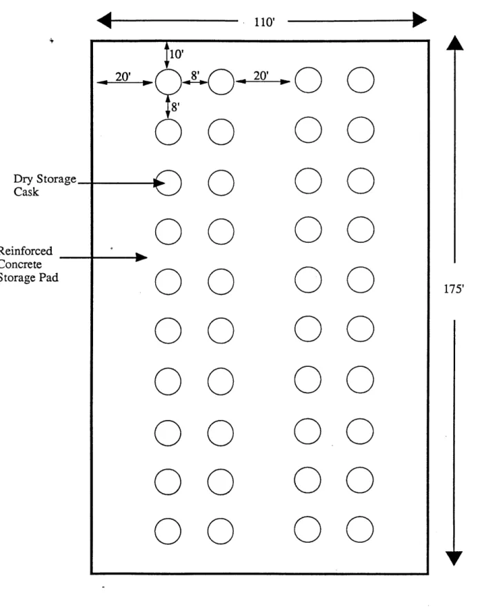
The buffer storage area consists of a set of reinforced concrete pads, on which the loaded fuel casks await repackaging. The modular design allows future additions when required due to delays in the repackaging procedure.
\
I' ~ /
y~j) ~
1'
S ______ I Main Gate S---a * a I a I I I a I I * a I I * a a * a I a * a I I a a S I Unconstructed :Pad I a I * U S a a a ~ a * I I a U I a * I ~ I 00 00o 00 00 00 00 00 00 100 001 0000o 00 00 00 00 o 00 00 00 00o 00 00 00 00 00 00 0 0 00 00 00 00 00 00 00 00 00 00 00 00 00 00 00 00 00 00 00 00 00 00 00 0 0 0 0 0 0 0 0 0 0 0 0 0 0 0 0 0 0 0 0 0o 00 00 00o 00 00 oo oo 00 00 o o o= o 0 0o 00o 1': 0 I Receiving Area : * : : II : j a : a Loading Area Main Track 1111111 111111I T I I I I I I I I A
Figure 2.8: Primary Facility Layout
Visitors Center
Security
Security Inner Perimeter
Administration and Operations
...
. . .. . . .. . . .
. . .. . . I