HAL Id: hal-03006464
https://hal.archives-ouvertes.fr/hal-03006464
Submitted on 30 Nov 2020
HAL is a multi-disciplinary open access
archive for the deposit and dissemination of
sci-entific research documents, whether they are
pub-lished or not. The documents may come from
teaching and research institutions in France or
abroad, or from public or private research centers.
L’archive ouverte pluridisciplinaire HAL, est
destinée au dépôt et à la diffusion de documents
scientifiques de niveau recherche, publiés ou non,
émanant des établissements d’enseignement et de
recherche français ou étrangers, des laboratoires
publics ou privés.
Pseudo-2-Fold Surface of the Al13Co4 Catalyst:
Structure, Stability, and Hydrogen Adsorption
Corentin Chatelier, Yves Garreau, Alina Vlad, Julian Ledieu, Andrea Resta,
Vincent Fournée, Marie-Cécile de Weerd, Alessandro Coati, Emilie Gaudry
To cite this version:
Corentin Chatelier, Yves Garreau, Alina Vlad, Julian Ledieu, Andrea Resta, et al.. Pseudo-2-Fold
Surface of the Al13Co4 Catalyst: Structure, Stability, and Hydrogen Adsorption. ACS Applied
Ma-terials & Interfaces, Washington, D.C. : American Chemical Society, 2020, 12 (35), pp.39787-39797.
�10.1021/acsami.0c09702�. �hal-03006464�
The pseudo-twofold surface of the Al
13
Co
4
catalyst:
structure, stability, and hydrogen adsorption
Corentin Chatelier
1,2, Yves Garreau
2,3, Alina Vlad
2, Julian Ledieu
1, Andrea Resta
2,
Vincent Fourn´
ee
1, Marie-C´
ecile de Weerd
1, Alessandro Coati
∗,2and ´
Emilie Gaudry
∗,1 ∗1Universit´e de Lorraine, CNRS, Institut Jean Lamour – UMR 7198, F-54011, Nancy, France 2Synchrotron SOLEIL, L’Orme des Merisiers, Saint-Aubin, BP 48, F-91192 Gif-sur-Yvette Cedex, France
3Universit´e de Paris, CNRS, Mat´eriaux et Ph´enom`enes Quantiques – UMR 7162, Paris, France
E-mail: [email protected],[email protected]
Abstract
A few low order approximants to decagonal quasicrystals have been shown to provide excellent activity and selectivity for the hydrogenation of alkenes and alkynes. It is the case for the Al13Co4compound, for which the
catalytic properties of the pseudo-twofold orientation have been revealed to be among the best. A combination of surface science studies, including Surface X-Ray Diffraction, and calculations based on Density Functional Theory, is used here to derive an atomistic model for the pseudo-twofold o-Al13Co4surface, whose faceted and
columnar structure is found very similar to the one of the twofold surface of the d-Al-Ni-Co quasicrystal. Facets substantially stabilize the system, with energies in the range 1.19–1.31 J/m2, i.e. much smaller than the ones of the pseudo-tenfold (1.49–1.68 J/m2) and pseudo-twofold (1.66 J/m2) surfaces. Faceting is also a main factor at
the origin of the Al13Co4catalytic performances, as illustrated by the comparison of the tenfold,
pseudo-twofold and facet potential energy maps for hydrogen adsorption. This work gives insights towards the design of complex intermetallics catalysts through surface nanostructuration for optimized catalytic performances.
Introduction
Since their discovery,1 quasicrystals have raised
sub-stantial interest regarding their unique chemical and physical properties. Coincident structural long-range order and absence of translational symmetry lead to remarkable transport properties,2–5 which are promis-ing for several uses, such as, for example, the control of wave localization for photonic applications.6 Even so, most promising applications rely on their surface-related properties, like oxidation resistance, high hard-ness, low coefficient of friction, and more recently cat-alytic activity.2,7 All of these properties are ultimately
related to the surface physics and chemistry at the atomic scale. Therefore, a detailed description of the surface structures is a prerequisite to understand how these surfaces interact with their environment.
High symmetry surfaces of quasicrystalline phases have been thoroughly investigated over the last years. Fivefold and tenfold surfaces generally present large flat terraces, corresponding to bulk truncations at spe-cific atomic planes.8–11Twofold surfaces were primarily considered as less stable.12–14 The former conclusion, drawn from the relative surface stabilities of icosahe-dral i-AlPdMn, appeared however to be not so clear, even non valid, for twofold surfaces of quasicrystals with different structures or/and compositions (i-AgInYb,15
i-AlPdRe,16 decagonal d-AlNiCo,17 d-AlCuCo18). In
these studies, relative surface stabilities of different
ori-entations were evaluated through the tendency to form facets, or through surface atomic densities, derived from the comparison of possible surface atomic arrangements with models built by bulk truncations. As far as we know, no validation has been achieved through precise surface energy calculations on these systems, due to the complexity and the non-periodic character of the struc-tures.
Periodic approximant structures to quasicrystals rep-resent a very useful approach to deepen our under-standing of quasicrystalline phases. Because they ex-hibit atomic arrangements similar to those encountered in quasicrystals, in large crystal cells, they bridge the gap between periodic and aperiodic positional order. They have nicely contributed to unveil the structure and properties of a few quasicrystalline surfaces, through density functional theory calculations using periodic boundary conditions, such as the fivefold surface of i-AlPdMn19,20 or the tenfold surface of d-AlCoNi.21
They were crucial for the discovery of templated single-element quasicrystalline thin film,22,23 or to
demon-strate that specific local atomic arrangement, favorable for selective catalytic properties, naturally appear at surfaces with pentagonal symmetry.24–26
A few low order approximants to decagonal quasicrys-tals have been shown to provide excellent activity and selectivity for alkene and alkyne hydrogenation.27–30 It is the case for the Al13TM4 compounds (TM =
identified as an important factor for the catalytic per-formances towards butadiene hydrogenation.30 Among them, the monoclinic m-Al13Fe4(010) was revealed as
the most active model catalyst at room temperature, and the orthorhombic o-Al13Co4(010) was determined
as the most active one at higher temperature (110
oC), while remaining 100% selective to butenes
un-like Al13Fe4(010). Regardless of temperature, the
o-Al13Co4(010) pseudo-twofold surface was found much
more active than the o-Al13Co4(100) pseudo-tenfold
ori-entation. While the pseudo-tenfold surface has been extensively studied these last years,31–35 very few is
known about the o-Al13Co4(010) peudo-twofold
sur-face structure and properties. On the basis of sursur-face science techniques, including Surface X-Ray Diffrac-tion (SXRD), combined with Density FuncDiffrac-tional The-ory (DFT) calculations, we derive a model at the atomic scale for the o-Al13Co4(010) faceted and
colum-nar structure, analogous to the one of the twofold d-Al-Ni-Co surface. Surface energy calculations iden-tify the facets as a main factor for the stability of the Al13Co4pseudo-twofold orientation, while potential
en-ergy maps for hydrogen adsorption suggest their role in the improved catalytic performances of o-Al13Co4(010)
towards hydrogenation reactions.
Materials and Methods
Al
13Co
4crystal structures
So far, six phases from the Al13Co4 family were
reported:36 Z-Al
3Co, Y1-Al13Co4, Y2-Al13Co4,
m-Al13Co4, o-Al13Co4, and o’ -Al13Co4, with slightly
dif-ferent structures. In this study, we used an orthorhom-bic crystal (o-Al13Co4), whose structure belong to the
Pmn21 space group (No. 31, Pearson symbol oP102)
and whose crystal cell is defined with the following lat-tice parameters: ao = 8.158 ˚A, bo = 12.342 ˚A, and co
= 14.452 ˚A (102 atoms per cell, Fig. 1(a)).37,38 The o-Al13Co4 compound is known to be unstable
at low temperatures, but stabilized at higher temper-atures by the entropy of Al vacancy hopping and low frequency vibrational modes.39 Monoclinic m-Al
13Co4
crystallizes in the C 2/m space group (No. 12, Pear-son symbol mC 102) with the lattice parameters: am
= 15.173 ˚A, bm = 8.109 ˚A, cm = 12.349 ˚A and
β = 107.84◦.40Because of the relatively close structures
of orthorhombic and monoclinic Al13Co4, their
coexis-tence is possible and can give rise to defects. Metadis-locations, due to plastic deformations,41–44 as well as
twins (Fig. S1),45 are frequent in complex intermetal-lic phases. Twins in Al13Co4 are generally related to
orthorhombic/monoclinic interfaces. In the following, ideal structures with full atomic occupations are con-sidered.
The Al13Co4monoclinic and orthorhombic structures
are approximant structures to decagonal d-AlNiCo qua-sicrystals, the o-[100] and m-[010] directions being iden-tified as the pseudo-tenfold directions, in o-Al13Co4and
(a) (b) (c) (d) ao co bm am F P bo co cm am
Figure 1: Bulk structure of (a) o-Al13Co4 along the o-[010]
direction showing the Henley-type clustering (in red and blue, both clusters are not crystallographically equivalent, the Al atoms in the center of the clusters do not have the same Wyckoff position, see section S3 of the supporting in-formation) as well as the stacking structure of F-type and P-type atomic planes, (b) m-Al13Co4 along the m-[001]
di-rection showing the Henley-type clustering (in blue, all the clusters are crystallographically equivalent, the Al atoms in the center of the clusters have the same Wyckoff position, see section S3 of the supporting information), (c) o-Al13Co4
along the pseudo-tenfold axis (the squashed-hexagonal tile, obtained by connecting together all Co atoms of the P-type plane, is highlighted in yellow and green) and (d) m-Al13Co4
structure along the pseudo-tenfold axis. Unlike o-Al13Co4
all hexagons of the hexagonal tile in the P-type plane have the same orientation in m-Al13Co4. The unit cells, Al and
Co atoms are drawn in black, light blue and dark blue, re-spectively.
m-Al13Co4, respectively. Their bulk structures are
de-scribed as a pile of two types of planes, perpendicular to the pseudo-tenfold axis, labeled alternatively flat-type (F-type) and puckered-type (P-type) planes (Fig. 1(a)). The stacking sequence is F0P0.25F0.5P0.75and the
inter-layer distance is approximately 2 ˚A. On the other hand, the approximant structure can be understood as a stack-ing of Henley-type clusters (in red and blue in Fig. 1(a– b)) where the F-type planes intercept the clusters in their meridian plane. The linear molecular group Co– Al–Co, parallel to the pseudo-tenfold axis, is character-ized by quite strong and covalent-like bonds.2,46,47The
orthorhombic and monoclinic phases differ in the rela-tive cluster arrangements. It is highlighted in Fig. 1(c– d) by the hexagonal-like tilings obtained by connecting together the Co atoms located in the P-type plane. In the monoclinic phase, all the hexagonal tiles point to-wards the same direction whereas they change orien-tation every other hexagon in the orthorhombic phase (Figs. 1(c) and 1(d)).
Experimental methods
We used an orthorhombic o-Al13Co4 single crystal,
grown from an aluminum rich solution using the Czochralski process. The ingot was oriented using back scattered x-ray Laue diffraction and cut perpendicular to the o-[010] direction. The sample was then polished using diamond paste down to 0.25 µm, as in our previ-ous studies.30,34
The sample was prepared in situ under ultra-high vacuum (UHV) conditions by cycles of Ar+
sputter-ing (1.5 kV for 30 minutes) followed by annealsputter-ing be-tween 873 K and 1073 K for 1 hour. The surface tem-perature has always been controlled using an infrared pyrometer (surface emissivity set to 0.3). The surface composition and cleanliness was ascertained using X-ray Photoelectron Spectroscopy (XPS, before Scanning Tunneling Microscopy (STM) analyses) or Auger Elec-tron Spectroscopy (AES, before SXRD experiments). Low Energy Electron Diffraction (LEED) patterns were recorded from 1 eV to 300 eV to check the surface orien-tation and the surface preparation under UHV. Atomic Force Microscopy (AFM) analyses were achieved at room conditions (pressure and temperature) with a Nano-I AFM from Pacific Nanotechnology Inc. used in close contact mode with a Si tip.
Surface diffraction measurements were performed at the Surfaces and Interfaces X-ray Scattering (SixS) beamline at Synchrotron SOLEIL. In SixS setup, the UHV preparation chamber (LEED, AES) is coupled with a UHV measurement chamber. The latter is mounted on a Z-axis diffractometer.48,49 Thanks to this setup, the transfer of the sample into the diffrac-tion chamber is done without any surface deterioradiffrac-tion. SXRD measurements were carried out at an energy of 18.41 keV and an incident angle of µ = 0.3◦. A 2D hybrid pixel detector (XPAD S140) was used to collect the scattered intensities50 and BINoculars program to
process the whole data set.51
AVE and ROD softwares (from the ANAROD suite52) were used to analyze the processed data gen-erated by BINoculars. Several crystal truncation rods (CTRs) were extracted. Structure factors of CTRs were simulated from DFT-relaxed surface models. The adequacy of the simulated CTRs intensities with the experimental data is quantified by the χ2 factor :
χ2= 1 Ndata− Np X Iexp− Ith σ 2 (1) where Ndata is the number of data points, Iexp (resp.
Ith) the experimental intensity (resp. simulated
inten-sity), Np the number of refined parameters and σ the
estimated error bar. In our case, only the scale factor is refined (Np = 1). Miller indices will further be
re-ferred to H, K and L (surface unit cell, orthorhombic structure).
Computational methods
DFT calculations were performed using the Vienna ab
initio simulation package (VASP).53 We applied the
spin polarized projector-augmented wave method,54,55
to describe the interactions between the valence elec-trons and the ionic core. We used the DFT-D3 approx-imation,56,57 because van der Waals forces are present
at metallic surfaces, and they non negligibly affect the surface energies.58 We considered atomic valences to
be 3s23p1 (Al) and 3d84s1 (Co). Total energies were
minimized until the energy differences were less than 10−6 eV between two electronic cycles. Atomic struc-tures – plotted using the VESTA software59– were re-laxed until the Hellmann-Feynman forces were as low as 0.02 eV/˚A. Calculations were performed using a 450 eV cut-off energy (Ecut) and Γ-centered 13×9×7 and
7×13×1 Monkhorst-Pack grids for bulk and surface cal-culations, respectively. Those parameters were chosen to achieve a precision for the total energy lower than 0.1 meV/atom. They result in cohesive energies for fcc Al (EAl
coh = –3.67 eV/at.) and hcp Co (ECocoh = –5.50
eV/at) in good agreement with the experimental data (EAl
coh = –3.39 eV/at. and EcohCo = –5.44 eV/at.). This
is the same for the formation enthalpy of orthorhom-bic o-Al13Co4 (∆HfAl13Co4 = −0.412 eV/at (calc) and
∆HAl13Co4
f = −0.41 eV/at (exp)
60). Relaxed bulk
structures are detailed in section S3 of the support-ing information. STM images were simulated ussupport-ing the Tersoff-Hamann approximation.61
The approach used to compute surface energies in this work is the typical symmetric slab model,62,63 already
used in our previous studies,35,64wherein a supercell of
the crystal oriented to expose its (hk`) surface is gen-erated, and atoms are removed from a portion of the supercell to create a vacuum (16 to 24 ˚A thick symmet-ric slabs, void thickness ' 16 ˚A). This set-up for sur-face modeling leads to sursur-face energies converged within less than 2.0 mJ/m2. In most cases, the stoichiometries
of our surface models are different from the bulk one. Surface energies are then determined as a function of the chemical potentials (µAl, µCo) and number of atoms
(NAl, NCo) in the slab:65 γ(hk`)σ =E σ slab(hk`)− NAlµAl− NCoµCo 2Aslab(hk`) (2) In the previous equation, the numerator can be under-stood as the difference between the total energy of the slab and the energy of the corresponding “bulk” with the same stoichiometry. The Al and Co chemical poten-tials in fcc Al and hcp Co (µbulk
Al and µbulkCo , respectively)
are taken as the cohesive energies calculated at T = 0 K.65 In the case of o-Al
13Co4, the Al and Co chemical
potentials are given by the Gibbs phase rule :
µbulk o-Al13Co4 = 13 µAl+ 4 µCo = 13 µbulk Al + 4 µ bulk Co + ∆H o-Al13Co4 f (3) Because the surface is considered to be in equilib-rium with the underlying o-Al13Co4bulk, they are
con-strained in a range, that is 17
13∆H
Al13Co4
f ≤ µAl−µbulkAl ≤
0. Formation energies of orthorhombic/monoclinic and monoclinic/monoclinic interfaces have been calculated as well, using :
Eintm/i= Etotsupercell− Em tot− E
i
tot (4)
where Eintm/i, Em
totand Eitotare the total energies of the
supercell (Fig. S1(a–b)), the monoclinic cell and the
i-type cell (i ∈ {o, m}), respectively.
The adsorption properties of the different surface structures considered in this work have been computed through potential energy maps. The adsorption has been computed on specific points of regular grids cover-ing the surfaces. For each specific point, all degrees of freedom of the uppermost layers and the z coordinate of the adsorbed hydrogen atom have been allowed to relax during the geometry optimizations, whereas the
x and y adsorbate coordinates have been frozen. The
adsorption energy (∆Eads) on the considered Al13Co4
surfaces is defined as follows :
∆Eads= E(H/slab) − E(slab) −
1
2E(H2) (5)
where E(H/slab), E(slab) and E(H2) are the total
elec-tronic energy of the adsorbed system, the bare support surface and the gas phase H2molecule, respectively. For
each surface, a potential energy map is built by an inter-polation over the series of adsorption energies calculated for each point of the grid.
Results and discussions
LEED - AFM - STM analyses
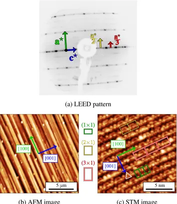
According to LEED measurements, a (1×1) surface structure is mainly observed (Fig. 2(a), Fig. S6a).
Dif-fuse scattering resembling a (2×1) and a (3×1) surface reconstructions is also visible beside the (1×1) surface structure. When scanning the energy range 1–300 eV, secondary peaks appear and move away from the cen-ter in between the main diffraction spots. They are attributed to the presence of facets at the surface. Con-tinuous intensity can also be seen in between the main diffraction spots. This signal could be linked to line or planar defects such as metadislocations or interfaces close to the surface.
According to AFM, a columnar structure appears along the o-[100] direction as shown in Fig. 2(b) (Fig. S6b). This feature is similar to that observed at the (12110) and (10000) two-fold d-Al-Ni-Co qua-sicrystalline surfaces,17 revealing faceting at the o-Al13Co4(010) surface. According to STM, terraces
ex-tend over a few hundreds of nanometers, separated by a single-step height equal to 6.1±0.2 ˚A, i.e. corresponding to half of the lattice parameter (bo/2 = 6.17 ˚A).
High-resolution images (Fig. 2(c), Fig. S6c) show a mixture of three different surface reconstruction motifs, in agree-ment with the LEED pattern, randomly distributed on the sample surface : (1×1), (2×1) and (3×1). These reconstructions may be due to local vacancies stabiliza-tion. For the (1×1) surface structure, a triangular motif is observed.
SXRD analysis
A large part of the reciprocal space was completely measured during the SXRD experiment: |Hmax| = 9.5,
|Kmax| = 5.5 and Lmax= 4.8. The o-(010) surface
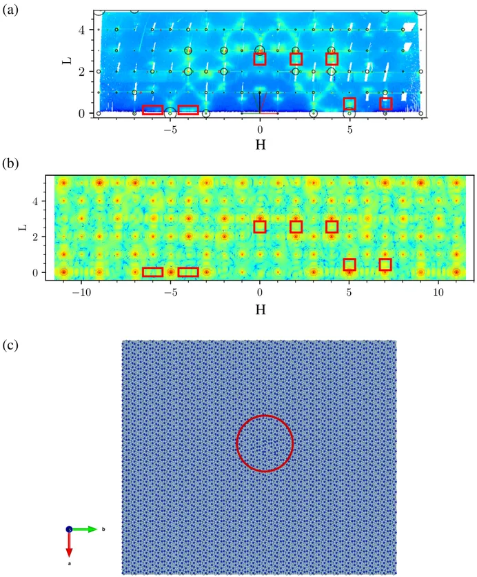
ori-entation is confirmed by the in-plane reciprocal space map of o-Al13Co4 (Fig. 3(a)). A total of 34
inequiva-lent CTRs were extracted from the measured reciprocal space region and further compared to DFT-based simu-lations using different surface structure models (see sec-tion page 6). Fig. 3(b) presents two out-of-plane (H,L) reciprocal space maps of o-Al13Co4(010) at K = 2 and K
= 3. The facets’ signal is clearly visible in the map at K = 2 : the facets’ rods make an angle of 54.2◦with the di-rection normal to the surface (indicated with green and red arrows in Fig. 3(b)). The facet’s rods do no inter-cept each other at the Bragg peaks of the orthorhombic structure (labeled with black circles), meaning that the facets do not present the o-Al13Co4 structure. Facets
are therefore related to the m-Al13Co4 structure. Two
types of twins are considered, the positions of their re-spective diffraction peaks are plotted in red and green circles (Fig. 3(b)). The facets’ rods intercept the m-(221) diffraction peaks. The facets are therefore con-sistent with a m-(201) orientation. Their signal is less clearly visible on the maps at an odd value of K but is still present. These conclusions are consistent with the fairly continuous intensity measured in between Bragg peaks along the H direction for integer values of K and L (similar observation as in LEED measurements, Figs. 2,3). This kind of signal can be produced by planar defects such as interfaces between two phases. It is
c
?c
?a
?a
? aa22?? aa33??(a) LEED pattern
(b) AFM image 5 μm [100] [001] (c) STM image 5 nm [001] [100] (1×1) (1×1) (2×1) (2×1) (3×1) (3×1)
Figure 2: (a) LEED pattern measured at 30 eV. Diffuse scattering resembling a (2×1) and a (3×1) surface recon-structions are shown in yellow and red arrows, respectively. (b) AFM image of o-Al13Co4(010) (15×15 µm2) showing a
columnar and faceted structure. (c) STM image of a flat terrace at the o-Al13Co4(010) surface (15×15 nm2) at Vb
= 0.6 V. The (1×1), (2×1) and (3×1) cells are drawn in green, yellow and red, respectively. A triangular motif is highlighted in white.
reasonable to assume these planar defects to be mon-oclinic/orthorhombic interfaces.
The formation of monoclinic/orthorhombic interfaces is calculated to be exothermic (Eintm/o =–4 mJ/m2).
Thus, they stabilize the structure, which may explain why they are naturally and profusely present in the bulk compound. For comparison, the formation en-ergy of monoclinic/monoclinic interfaces is endothermic (Eintm/m= 50 mJ/m2).
Additional information can be extracted from SXRD. Intensity is observed in between integer values of K (in-dicated by a yellow rectangle in Fig. 3(a) for K = 3.5). Complementary SXRD analysis suggests that this signal arises from a bulk defect and not from the surface itself. Other distinct features can be seen in the map (H,L) for K = 2 and a few examples of them are framed in orange in Fig. 3(b). They are neither part of the orthorhombic nor of the monoclinic (facets) lattices. Some comple-mentary simulations of the reciprocal space – Fourier transform of a model atomic structure – suggest that they may be generated by metadislocations close to the surface (section S1, Figs. S2-S3 of the supporting infor-mation).
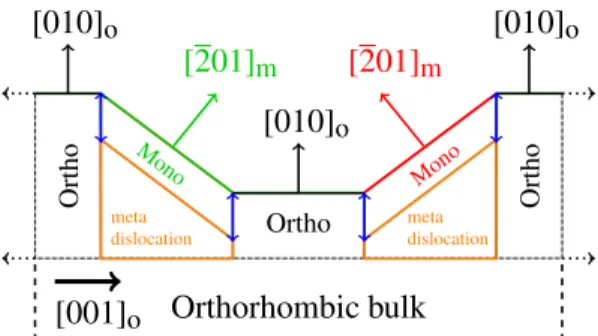
To summarize, the SXRD analysis led to a
macro-scopic surface structure model for of o-Al13Co4(010). It
consists in a coexistence of orthorhombic (flat terraces) and monoclinic (facets) structures at the surface sepa-rated by monoclinic/orthorhombic interfaces, as well as the possible presence of metadislocations close to the surface (Fig. 4).
Surface energy calculations
o-Al13Co4(010)Bulk o-Al13Co4 cannot be described as a stacking of
well-separated atomic layers along the o-[010] direction (Fig. 5(a)). Our strategy to build surface models was then the following: first, eight bulk truncated models – almost regularly spaced along [010] – were considered (labeled O0 to O5.7, depending on the distance in ˚A to
the center of the cell, e.g. 0.6 ˚A), before we refine the most stable models identified in the first step. Varia-tions of models O0.6 and O1.2 (named Oi0.6 and O
i
1.2)
were then considered. Thus, a total of 17 models were investigated . Their surface atomic structures are drawn in Fig. 5(b). Because of the symmetry (glide mirror) along o-[010], only half of a unit cell was investigated.
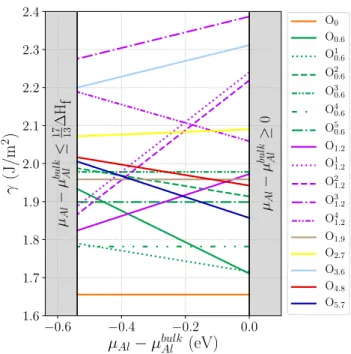
The surface energies of the considered models are summarized in Fig. 6. Less stable models, i.e. O3
1.2
and O3.6, with the largest surface energies (between 2.2
and 2.38 J/m2), as well as O1
1.2, O21.2, O41.2 and O2.7,
with surface energies ranging from 1.86 to 2.24 J/m2,
present low atomic density terminations combined with the presence of isolated Co. The surface energies for models with higher surface atomic density (O0.6, Oi0.6,
O1.9, O4.8 and O5.7) are smaller: they range from 1.72
to 2.02 J/m2. Several models keep intact at their sur-face the strong covalent-like Co–Al–Co linear molecular groups : O0, O10.6, O40.6, O1.2, O11.2 and O21.2. They are
found to be amongst the 8 most stable surface models for the whole range of allowed chemical potentials. The surface energy of the most stable model (O0) is quite
lower than the other considered models. It does not de-pend on the chemical potentials (1.66 J/m2), since the
stoichiometry of the slab used for the calculation is the one of the bulk crystal. It is described as a flat termina-tion consisting of rows of protruding triangular motifs made of aluminum atoms separated by a 6.5 ˚A gap, while maintaining intact the strongly bound Co–Al–Co molecular group at the surface.
m-Al13Co4(201)
Experimental SXRD measurements identified facets as
m-Al13Co4(201). As previously, 17 bulk truncated
mod-els – Fig. 7(a) – were built, by progressively removing atoms at the surface (labeled M0 to M7.2 with a step
of 0.45 ˚A, depending on the distance in ˚A to the cen-ter of the cell, e.g. 7.2 ˚A). Due to the symmetry of the monoclinic lattice, only half of the cell was considered. Models M0 to M1.35 are Al-rich surface models with a
progressively increasing surface atomic density. Models M1.8 to M3.15, as well as models M6.75 and M7.2 have
(a)
(b)
0 5 10 -5 -10 H 0 5 -5 K c? bulk a? bulk 0 3 6 9 -3 -6 -9 H 0 1 2 3 4 L 0 3 6 9 -3 -6 -9 H 0 1 2 3 4 L [201]m [201]m L = 0 K = 2 K = 3Figure 3: (a) In-plane (H,K) reciprocal space map of o-Al13Co4. The diffraction spots of the orthorhombic phase are indexed
with black circles. The region presented in Fig. S2 is drawn in red. (b) Out-of-plane (H,L) – for K = 2 and K = 3 respectively – reciprocal space maps of o-Al13Co4. The position of the monoclinic diffraction spots are represented in green and red circles
(two different twins). Facets appear to present the m-(201) orientation. Blank regions are areas where the signal was too intense to be collected (too close to Bragg peaks).
[201]
m[201]
m[010]
o[010]
o[010]
o Ortho Ortho OrthoOrthorhombic bulk
Mono Mono meta dislocation meta dislocation[001]
oFigure 4: Schematic of the suggested surface model based on the experimental observations. Orthorhombic flat terraces and monoclinic facets coexist in this model and are drawn in black and red/green (two different twins), respectively. Monoclinic/orthorhombic interfaces are represented in blue. Metadislocations are displayed in orange.
dense Co-rich terminations, while models M3.6 to M6.3
are less dense with a few Co atoms in the surface plane. The strong Co–Al–Co covalent-like bond is kept intact at the surface in models M2.7, M3.15, M4.95 M5.4, M5.85.
Surface energy calculations are summarized in Fig. 8. M1.8 presents the highest surface energy (ranging from
1.91 to 2.39 J/m2) due to a low atomic surface density combined with a Co-rich composition. In the Co-rich limit, the model M3.15, which has a dense termination
plane (highest surface atomic density 0.19 at/˚A2) and
keeps intact the strong Co–Al–Co covalent-like bond at the surface, clearly presents the lowest surface energy (1.19 J/m2). In the Al-rich limit, four models present
rather low surface energies: models M5.85, M3.15, M1.35
and M0.9. The most stable ones are the Al-rich models
(M1.35 and M0.9), with a similar surface energy (1.25
J/m2). The M3.15 surface model is the most stable one
over the longest range of Al chemical potentials and therefore will be considered for further investigations.
Detailed surface model for the
pseudo-twofold surface of o-Al
13Co
4As presented in Fig. 4, the twofold surface of Al13Co4
consist in terraces of o-Al13Co4(010) and facets,
identified as m-Al13Co4(¯201). Focusing on the
o-Al13Co4(010) surface, the O0 model (Fig. S7) has
been identified as a stable surface model with a rather low surface energy (1.66 J/m2). To complete the ther-modynamic approach, STM images (Fig. 9) and SXRD rods (Fig. 10, Tab. 1) are simulated using stable surface models.
Theoretical STM images are compared to both the ex-perimental measurements and their filtered (2D FFT) counterparts. On the 2D FFT filtered image, rows of tri-angular motifs separated by a 0.65 nm gap are observed. Only five models reproduce relatively well this feature : O0, O30.6, O50.6, O31.2 and O41.2, because the atomic
arrangement at the surface include a triplet made of ei-ther Al3or CoAl2atomic ensembles. In most cases – the
O0, O30.6 and O50.6 are good examples – the bright/dark
protrusions are due to atoms slightly above/below the mean position of the termination plane. So far, the STM image simulated using the O0 or O41.2 models show the
O
0O
1.2O
2.7O
4.8O
0.6O1.9
O3.6
O
5.7 ao bo O0 O0.6 O10.6 O20.6 O30.6 O40.6 O5 0.6 O1.2 O11.2 O21.2 O31.2 O41.2 O1.9 O2.7 O3.6 O4.8 O5.7 ao co(a)
(b)
Figure 5: (a) Bulk truncation models that were considered. (b) Surface structure models O0 to O5.7. Unit cells, Al and Co
atoms are drawn in black, light blue and dark blue, respectively.
−0.6 −0.4 −0.2 0.0
µ
Al− µ
bulkAl(eV)
1.6 1.7 1.8 1.9 2.0 2.1 2.2 2.3 2.4γ
(J/m
2)
µAl − µ bul k Al ≤ 17 ∆H 13 f µAl − µ bul k Al ≥ 0 O0 O0.6 O1 0.6 O2 0.6 O3 0.6 O4 0.6 O5 0.6 O1.2 O1 1.2 O2 1.2 O3 1.2 O4 1.2 O1.9 O2.7 O3.6 O4.8 O5.7Figure 6: Surface energies of 17 surface models for o-Al13Co4(010) as a function of µAl− µbulkAl .
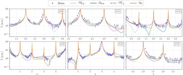
The structure factors of the 34 inequivalent CTRs ex-tracted from the X-ray diffraction measurements were simulated using the DFT-relaxed surface models. Four models were tested (O0, O0.6, O10.6 and O41.2) based on
the surface energy calculations and the STM image sim-ulations. As shown in Tab. 1, O0 is overall the best
fitting surface model having the lowest χ2and R-factor
values (Fig. 10) and reproduce quite well a lot of ob-served features. This model consists in a flat termina-tion with rows along the [100] (pseudo-tenfold) direc-tion, made of protruding triangular motifs of aluminum atoms separated by a 6.5 ˚A gap. The strong anisotropy in the surface plane may reflect the one observed on twofold surfaces of decagonal quasicrystals, spanned by perpendicular periodic and aperiodic axes. Focusing on the facets, the M3.15surface model (Fig. S8) is the most
stable one over the longest range of Al chemical poten-tials. A deep pseudo-gap at the Fermi energy is also identified in the corresponding density of states, which shows similar features to that of the O0 model.
Table 1: X-ray diffraction results – ROD analysis.
Surface Model O0 O0.6 O10.6 O41.2
Scale factor 0.0197 0.0199 0.0198 0.0189
χ2 6.107 6.137 7.145 7.269
Now that the structure of the pseudo-twofold surface is known, it is of interest to compare its stability to the one of the pseudo-tenfold surface. Without regarding the facets, the relative stabilities of the pseudo-twofold (O0 model) and pseudo-tenfold surfaces rely on the Al
chemical potential (Fig. 11). Two surface models are available for the pseudo-tenfold surface: a dense Al-rich flat plane, identified by a combination of surface science studies and DFT calculations (P24),32–34 and
a highly corrugated model, keeping intact the Henley-type clusters at the surface (P14),24,35,46 build by a
Models M0to M 7.2 (201)m am cm M0 M0.45 M0.9 M1.35 M1.8 M2.25 M2.7 M3.15 M3.6 M4.05 M4.5 M4.95 M5.4 M5.85 M6.3 M6.75 M7.2
b
faceta
facet (a) (b)Figure 7: (a) Bulk (monoclinic structure) truncation models considered in this work. (b) Surface structures of models M0
and M7.2. Unit cells, Al and Co atoms are drawn in black, light blue and dark blue, respectively.
−0.6 −0.4 −0.2 0.0
µ
Al− µ
bulkAl(eV)
1.0 1.2 1.4 1.6 1.8 2.0 2.2 2.4γ
(J/m
2)
µAl − µ bul k Al ≤ 17 ∆H13 f µAl − µ bul k Al ≥ 0 M0 M0.45 M0.9 M1.35 M1.8 M2.25 M2.7 M3.15 M3.6 M4.05 M4.5 M4.95 M5.4 M5.85 M6.3 M6.75 M7.2Figure 8: Surface energies of 17 surface models for m-Al13Co4(¯201) as a function of µAl− µbulkAl .
theoretical cleavage (Figs. S4-S5). In the Al-rich re-gion (0 > µAl− µbulkAl > −0.16 eV), the pseudo-tenfold
surface (P24 model) is more stable than the
pseudo-twofold one (O0model). The situation is quite different
in the Co-rich region, (17
13∆Hf < µAl− µ bulk
Al < −0.16
eV), where the surface energies of the pseudo-twofold (O0 model) and pseudo-tenfold (P14 model) surfaces
are very close, thus suggesting a similar stabilization. The surface energy anisotropy, without regarding the facets, is smaller than that of fcc Al and hcp Co (0.81
< γAl13Co4twofold
γAl13Co4tenfold < 1.11).
66,67 Focusing on the facets (M
3.15
model), they turn up to be the most stable in the full range of allowed chemical potentials, with surface ener-gies ranging from 1.19 J/m2(Co-rich potentials) to 1.31
J/m2(Al-rich potentials). Thus, they substantially
con-tribute to stabilize the pseudo-twofold orientation over the pseudo-tenfold one.
STM (filtered image)2D FFT O0 O0.6 O10.6 O20.6 O3 0.6 O40.6 O50.6 O1.2 O11.2 O21.2 O3 1.2 O41.2 O5.7
Figure 9: STM image simulations (models O0, O0.6, O1.2
and O5.7) and comparison to experimental images (Vb =
Figure 10: Example of six extracted CTRs of o-Al13Co4(010) and their related DFT-based ROD simulation. −0.6 −0.4 −0.2 0.0
µ
Al− µ
bulkAl(eV)
1.2 1.4 1.6 1.8 2.0γ
(J/m
2)
µAl − µ bul k Al ≤ 17 ∆H13 f µAl − µ bul k Al ≥ 0 O0 M3.15 P24 P14Figure 11: Comparison of o-Al13Co4(100) (models P24
and P14), o-Al13Co4(010) (model O0) and m-Al13Co4(201)
(model M3.15) surface energies as a function of µAl− µbulkAl .
Potential energy maps for hydrogen
ad-sorption
The gas-phase butadiene hydrogenation performances of the pseudo-twofold and pseudo-tenfold o-Al13Co4
surfaces have been recently compared.30 The pseudo-twofold orientation is found to be the most active at 110oC, and even more selective to butene (100%) than
previously investigated Al13Fe4(010).28,29
Weak hydrogen binding and easy H2 dissociation are
key descriptors in hydrogenation catalysis. A small dissociation barrier (0.18 eV) has already been deter-mined on o-Al13Co4(100) (P14 model).24 It is smaller
than the one calculated on the P24 model for
o-Al13Co4(100) (0.59 eV).68 On the o-Al13Co4(010) and
m-Al13Co4(¯201) surfaces, a spontaneous dissociation of
H2 occurs on top of surface Co atoms. We then
fo-cus on the atomic hydrogen adsorption properties of the different Al13Co4 surfaces, an overview of which is
obtained through potential energy surfaces (Fig. 12). The adsorption has been computed on specific points of regular grids covering the surfaces, using point densi-ties of 1.0 pts.˚A−2, 2.3 pts.˚A−2and 1.6 pts.˚A−2, for the
o-Al13Co4(010), o-Al13Co4(100) and m-Al13Co4(¯201),
respectively.
The energy landscape is quite contrasted on the dif-ferent terminations considered here. Focusing on the pseudo-tenfold orientation – for which two surface mod-els have been identified – the reaction conditions may in-deed modify the Al-rich and relatively flat surface struc-ture observed under ultra-high vacuum (P24 model),
in the form of highly cohesive clusters emerging from the bulk lattice (P14 model),35 to give rise to a
nanos-tructured surface demonstrated to be more active.24,35 Hydrogen is calculated to be quite weakly bound on the P24 model (Eads> –0.23 eV), the most stable sites
being located on Al-Al bridges above a subsurface Co atom, and slightly more strongly adsorbed on the P14
model (Eads > –0.58 eV), the more stable sites being
located on top of the Al ”glue” atoms that connects the bipentagonal Al motif, or in the vicinity of protruding Co atoms. On both surface models, favorable hydrogen adsorption sites remain poorly connected.
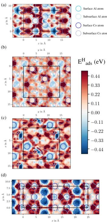
The picture is slightly different on the pseudo-twofold surface. Atomic hydrogen is found to be strongly bound to the surface, either on top of Al atoms located above subsurface Co atoms (O0model, Eads> –0.59 eV) or on
top of Co atoms (M3.15 model, Eads > –0.53 eV). This
suggests that hydrogen dissociation is likely on this sur-face. Additional favorable adsorption sites are found on top or in the vicinity of surface Co atoms, but with weaker adsorption energies, i.e. likely active for hydro-genation steps. All these sites are well connected to one another and it is reasonable to assume that the dif-fusion of hydrogen atoms on this surface is facilitated. Thus, the comparison of the hydrogen adsorption po-tential energy maps gives helpful insights to understand the better catalytic performances of the pseudo-twofold surface compared to the pseudo-tenfold one.
Conclusion
The structure, stability and hydrogen adsorption prop-erties of the Al13Co4 pseudo-twofold surface have been
investigated by a combination of experimental (LEED, AFM, STM and SXRD) and theoretical (DFT calcu-lations) techniques. A highly faceted surface morphol-ogy, has been identified, similar to that of the d-Al-Ni-Co (12110) and (10000) twofold quasicrystalline sur-faces. Our surface model consists in a coexistence of both flat terraces (o-Al13Co4(010)), made of rows of
triangular Al3 motifs separated by a 0.65 nm gap, and
facets (m-Al13Co4(¯201)), with a fairly denser and
Co-enriched atomic surface structure. The strong Co–Al– Co covalent-like molecular group identified in the bulk is kept intact at the surface in both terraces and facets. The pseudo-twofold Al13Co4 surface is calculated to
be less stable than the pseudo-tenfold surface in the Al-rich limit (1.66 J/m2 vs 1.49 J/m2 for µ
Al = µbulkAl ),
while both orientations present similar surface energies in the Al-rich region (1.66–1.68 J/m2). Without
regard-ing the facets, the surface energy anisotropy is smaller than that of fcc Al and hcp Co (0.81 < γtwofoldAl13Co4
γtenfoldAl13Co4 <
1.11).66,67 Facets substantially stabilize the pseudo-twofold surface orientation. Their surface energies are indeed calculated to be much lower than the previous ones ([1.19 J/m2 : 1.31 J/m2]).
Based on our surface model for the pseudo-twofold surface structure, potential energy maps for atomic hy-drogen adsorption have been built. They show a wide diversity of favorable atomic hydrogen adsorption sites, some of them being quite strongly bound to the surface (–0.60 < Eads(H) < –0.50 eV), thus likely promoting H2
dissociation, while others interact more weakly with the surface, and are possibly more active for hydrogenation
(a) (b) (c) (d)
E
H
ads
(eV)
Surface Al atom Subsurface Al atom Surface Co atom Subsurface Co atomFigure 12: Adsorption energy maps of monoatomic hydrogen on (a) o-Al13Co4(010) model O0, (b) o-Al13Co4(100) model
P24, (c) o-Al13Co4(100) model P14and (d) m-Al13Co4(201)
steps. As already predicted for the pseudo-tenfold ori-entation,35 reaction conditions may modify the faceted structure of the pseudo-twofold surface identified un-der ultra-high vacuum conditions. Further experimen-tal and theoretical works – under caexperimen-talytic conditions – are therefore needed to fully understand the mechanism behind the catalytic properties of o-Al13Co4(010).
Acknowledgement C.C. acknowledges Synchrotron
SOLEIL and R´egion Grand Est for financial sup-port. The authors thank Benjamin Voisin for tech-nical support throughout the SXRD experiments and Dr. Mich`ele Sauvage-Simkin for fruitful discussions. The authors also thank Dr. S. Kubsky, F. Nico-las and A. Loncle from SOLEIL Surface Laboratory for providing AFM equipment and support. This work is supported by the European Integrated Cen-ter for the Development of New Metallic Alloys and Compounds. E.G. acknowledge financial support through the COMETE project (COnception in silico de Mat´eriaux pour l’EnvironnemenT et l’ ´Energie) co-funded by the European Union under the program
F EDER-FSE Lorraine et Massif des Vosges 2014-2020.
This work was granted access to the HPC resources of TGCC, CINES and IDRIS under the allocation 99642 attributed by GENCI (Grand Equipement National de Calcul Intensif). High Performance Computing re-sources were also partially provided by the EXPLOR centre hosted by the University de Lorraine (project 2017M4XXX0108).
Supporting Information Available
Twins and metadislocations in Al13Co4; o-Al13Co4(100)
surface models (P14 and P24); Relaxed Al13Co4 bulk
structures; LEED-AFM-STM; o-Al13Co4(010) and
m-Al13Co4(¯201) surface models (O0 and M3.15)
References
(1) Shechtman, D.; Blech, I.; Gratias, D.; Cahn, J. Metallic Phase with Long-Range Orientational Order and No Translational Symmetry. Phys. Rev.
Lett. 1984, 53, 1951–1953.
(2) Dubois, J. M. Properties and Applications of Qua-sicrystals and Complex Metallic Alloys . Chem.
Soc. Rev. 2012, 41, 6760–6777.
(3) Belin-Ferr´e, E., Ed. Properties and Applications of
Complex Intermetallics; World Scientific
Publish-ing: Singapore, 2008.
(4) Roche, S.; de Laissardi`ere, G. T.; Mayou, D. Elec-tronic Transport Properties of Quasicrystals. J.
Math. Phys. 1997, 38, 1794.
(5) Ahn, S. J.; Moon, P.; Kim, T.-H.; Kim, H.-W.; Shin, H.-C.; Kim, E. H.; Cha, H. W.; Kahng, S.-J.; Kim, P.; Koshino, M. et al. Dirac Electrons
in a Dodecagonal Graphene Quasicrystal. Science
2018, 361, 782–786.
(6) Jeon, S.; Kwon, H.; Hur, K. Intrinsic Photonic Wave Localization in a Three-Dimensional Icosa-hedral Quasicrystal. Nat. Phys. 2017, 13, 363– 368.
(7) Thiel, P. Quasicrystal Surfaces. Annu. Rev. Phys.
Chem. 2008, 59, 129.
(8) Sharma, H.; Fourn´ee, V.; Shimoda, M.; Ross, A.; Lograsso, T.; Tsai, A.; Yamamoto, A. Structure of the Fivefold Surface of the Icosahedral Al-Cu-Fe Quasicrystal: Experimental Evidence of Bulk Truncations at Larger Interlayer Spacings. Phys.
Rev. Lett. 2004, 93, 165502–1.
(9) Papadopolos, Z.; Kasner, G.; Ledieu, J.; Cox, E. J.; Richardson, N. V.; Chen, Q.; Diehl, R. D.; Lograsso, T. A.; Ross, A. R.; Mc-Grath, R. Bulk Termination of the Quasicrys-talline Fivefold Surface of Al70Pd21Mn9. Phys.
Rev. B 2002, 88, 184207.
(10) Sharma, H.; Shimoda, M.; Sagisaka, K.; Takakura, H.; Smerdon, J.; Nugent, P.; Mc-grath, R.; Fujita, D.; Ohhashi, S.; Tsai, A. Struc-ture of the Fivefold Surface of the Ag-In-Yb Icosahedral Quasicrystal. Phys. Rev. B 2009, 80, 121401.
(11) Ledieu, J.; Fourn´ee, V. Surfaces of quasicrystals.
C. R. Physique 2014, 15, 48–57.
(12) Shen, Z.; Raberg, W.; Heinzig, M.; Jenks, C.; Fourn´ee, V.; Van-Hove, M.; Lograsso, T.; De-laney, D.; Cai, T.; Canfield, P. et al. A LEED Comparison of Structural Stabilities of the Three High-Symmetry Surfaces of Al-Pd-Mn Bulk Qua-sicrystals. Surf. Scie. 2000, 450, 1–11.
(13) Shen, Z.; Jenks, C.; Anderegg, J.; Delaney, D. W.; Lograsso, T. A.; Thiel, P.; Goldman, A. Structure and Stability of the Twofold Surface of Icosahedral Al-Pd-Mn by Low-Energy Electron Diffraction and X-Ray Photoemission Spectroscopy. Phys.
Rev. Lett. 1997, 78, 1050–1053.
(14) Kluge, F.; Yurechko, M.; Urban, K.; Ebert, P. In-fluence of Growth Kinetics and Chemical Com-position on the Shape of Voids in Quasi-Crystals.
Surf. Sci. 2002, 519, 33–39.
(15) Cui, C.; Nugent, P. J.; Shimoda, M.; Ledieu, J.; Fourn´ee, V.; Tsai, A. P.; McGrath, R.; Sharma, H. R. Structure of the Twofold Surface of the Icosahedral Ag-In-Yb Quasicrystal. J. Phys.:
(16) Tamura, R.; Yadav, T.; McLeod, I.; Hesp, D.; Young, K.; Nakamura, T.; Nishio, K.; Dhanak, V.; McGrath, R.; Sharma, H. Scanning Tunneling Mi-croscopy of a Polygrain Al-Pd-Re Quasicrystal: Study of the Relative Surface Stability. J. Phys.:
Condens. Matter 2013, 25, 395007.
(17) Mader, R.; Widmer, R.; Groning, P.; Deloudi, S.; Steurer, W.; Heggen, M.; Schall, P.; Feuer-bacher, M.; Groning, O. High-Resolution Scan-ning Tunneling Microscopy Investigation of the (12110) and (10000) Two-Fold Symmetric d-Al-Ni-Co Quasicrystalline Surfaces. Phys. Rev. B 2009,
80, 035433.
(18) Duguet, T.; Unal, B.; de Weerd, M. C.; Ledieu, J.; Ribeiro, R. A.; Canfield, P. C.; Deloudi, S.; Steurer, W.; Jenks, C. J.; Dubois, J. M. et al. Twofold Surface of the Decagonal Al-Cu-Co Qua-sicrystal. Phys. Rev. B 2009, 80, 024201.
(19) Krajˇc´ı, M.; Hafner, J. Structure, Stability and Electronic Properties of the i-AlPdMn Quasi-cristalline Surface. Phys. Rev. B 2005, 71, 054202. (20) Krajˇc´ı, M.; Hafner, J.; Ledieu, J.; McGrath, R. Surface Vacancies at the Fivefold Icosahedral Al-Pd-Mn Quasicrystal Surface: A Comparison of Ab Initio Calculated and Experimental STM Images.
Phys. Rev. B 2006, 73, 024202.
(21) Krajˇc´ı, M.; ; Hafner, J.; Mihalkoviˇc, M. Ab ini-tio study of the surface of a decagonal Al-Co-Ni quasicrystal. Phys. Rev. B 2006, 73, 134203. (22) Franke, K.; Sharma, H.; Theis, W.; Gille, P.;
Ebert, P.; Rieder, K. Quasicrystalline Epitaxial Single Element Monolayers on Icosahedral Al-Pd-Mn and Decagonal Al-Ni-Co Quasicrystal Sur-faces. Phys. Rev. Lett. 2002, 89, 156104.
(23) Sharma, H. R.; Nozawa, K.; Smerdon, J. A.; Nu-gent, P. J.; McLeod, I.; Dhanak, V. R.; Shi-moda, M.; Ishii, Y.; Tsai, A. P.; McGrath, R. Tem-plated Three-Dimensional Growth of Quasicrys-talline Lead. Nat. Commun. 2013, 4, 2715. (24) Krajˇc´ı, M.; Hafner, J. Complex Intermetallic
Com-pounds as Selective Hydrogenation Catalysts - A Case Study for the (100) Surface of Al13Co4. J.
Catal. 2011, 278, 200–207.
(25) Krajˇc´ı, M.; Hafner, J. The (210) Surface of In-termetallic B20 Compound GaPd as a Selective Hydrogenation Catalyst: a DFT Study. J. Catal.
2012, 295, 70–80.
(26) Krajci, M.; Hafner, J. Surfaces of Intermetallic Compounds: an Ab Initio DFT Study for B20-Type AlPd. Phys. Rev. B 2013, 87, 035436.
(27) Armbr¨uster, M.; Kovnir, K.; Friedrich, M.; Teschner, D.; Wowsnick, G.; Hahne, M.; Gille, P.; Szentmiklosi, L.; Feuerbacher, M.; Heggen, M. et al. Al13Fe4 as a Low-Cost Alternative for
Palladium in Heterogeneous Hydrogenation. Nat.
Mater. 2012, 11, 690–693.
(28) Piccolo, L. Al13Fe4 Selectively Catalyzes the
Hy-drogenation of Butadiene At Room Temperature.
Chem. Commun. 2013, 49, 9149–9151.
(29) Piccolo, L.; Kibis, L. The Partial Hydrogenation of Butadiene over Al13Fe4 : A Surface-Science
Study of Reaction and Deactivation Mechanisms.
J. Catal. 2015, 332, 112.
(30) Piccolo, L.; Chatelier, C.; de Weerd, M.-C.; Morfin, F.; Ledieu, J.; Fourn´ee, V.; Gille, P.; Gaudry, E. Catalytic Properties of Al13TM4
Com-plex Intermetallics: Influence of the Transition Metal and the Surface Orientation On Butadiene Hydrogenation. Sci. Tech. Adv. Mater. 2019, 20, 557–567.
(31) Addou, R.; Gaudry, ´E.; Deniozou, T.; Heggen, M.; Feuerbacher, M.; Gille, P.; Grin, Y.; Widmer, R.; Groening, O.; Fourn´ee, V. et al. Investigation of the (100) Surface of the Orthorhombic Al13Co4
Crystal. Phys. Rev. B 2009, 80, 014203.
(32) Shin, H.; Pussi, K.; Gaudry, ´E.; Ledieu, J.; Fourn´ee, V.; Alarc´on-Villaseca, S.; Dubois, J.-M.; Grin, Y.; Gille, P.; Moritz, W. et al. Structure of the Orthorhombic Al13Co4(100) Surface Using
LEED, STM and Ab Initio Studies. Phys. Rev. B
2011, 84, 085411 (1to11).
(33) Ledieu, J.; Gaudry, E.; de Weerd, M.-C.; Diehl, R. D.; Fourn´ee, V. The (100) Surface of the Al13Co4 Quasicrystalline Approximant. Mater.
Res. Soc. Symp. Proc. 2012, 1517 .
(34) Gaudry, E.; Chatelier, C.; McGuirk, G.; Loli, L. S.; DeWeerd, M.-C.; Ledieu, J.; Fourn´ee, V.; Fe-lici, R.; Drnec, J.; Beutier, G. et al. Structure of the Al13Co4(100) Surface: Combination of
Sur-face X-Ray Diffraction and Ab Initio Calculations.
Phys. Rev. B 2016, 94, 165406.
(35) Gaudry, E.; Chatelier, C.; Loffreda, D.; Kan-daskalov, D.; Coati, A.; Piccolo, L. Catalytic acti-vation of a non-noble intermetallic surface through nanostructuration under hydrogenation conditions revealed by atomistic thermodynamics. J. Mater.
Chem. A 2020, 8, 7422–7431.
(36) Priputen, P.; Kus´y, M.; Drienovsk´y, M.; Janiˇckoviˇc, D.; Ciˇˇ cka, R.; Cerniˇˇ ckov´a, I.; Janovec, J. Experimental Reinvestigation of AlâĂŞCo Phase Diagram in Vicinity of Al13Co4
Family of Phases. J. Alloys Compd. 2015, 647, 486–497.
(37) Grin, J.; Burkhardt, U.; Ellner, M.; Peters, K. Crystal Structure of Orthorhombic Co4Al13. J.
Al-loys Compd. 1994, 206, 243–247.
(38) Burkhardt, U.; Ellner, M.; Grin, Y.; Baumgart-ner, B. Powder Diffraction Refinement of the Co2Al5 Structure. Powder Diffr. 1998, 13, 159–
162.
(39) Mihalkoviˇc, M.; Widom, M. First-Principles Cal-culations of Cohesive Energies In the Al-Co Binary Alloy System. Phys. Rev. B 2007, 75, 014207. (40) Hudd, R.; Taylor, W. The Structure of Co4Al13.
Acta Cryst. A 1962, 15, 441.
(41) Feuerbacher, M.; Heggen, M. On the Concept of Metadislocations in Complex Metallic Alloys.
Phi-los. Mag. 2006, 86, 935–944.
(42) Heggen, M.; Houben, L.; Feuerbacher, M. Metadislocations in the Structurally Complex Or-thorhombic Alloy Al13Co4. Philos. Mag. 2008, 88,
2333–2338.
(43) Heggen, M.; Houben, L.; Feuerbacher, M. Plastic-Deformation Mechanism in Complex Solids. Nat.
Mater. 2010, 9, 332–336.
(44) Heidelmann, M.; Heggen, M.; Dwyer, C.; Feuer-bacher, M. Comprehensive Model of Metadisloca-tion Movement in Al13Co4. Scr. Mater. 2015, 98 .
(45) Saito, K.; Sugiyama, K.; Hiraga, K. Al13M4-type
Structures and Atomic Models of their Twins.
Mater. Sci. Eng. A 2000, 294-296, 279–282.
(46) Scheid, P.; Chatelier, C.; Ledieu, J.; Fourn´ee, V.; Gaudry, E. Bonding Network and Stability of Clusters: The Case Study of the Al13TM4
Pseudo-10fold Surfaces. Acta Crystallogr. A 2019, 75, 314–324.
(47) Jeglic, P.; Vrtnik, S.; Bobnar, M.; Klanjsek, M.; Bauer, B.; Gille, P.; Grin, Y.; Haarmann, F.; Dolinsek, J. M-Al-M Groups Trapped in Cages of Al13M4(M=Co, Fe, Ni, Ru) Complex
Intermetal-lic Phases as Seen via NMR. Phys. Rev. B 2010,
82, 104201.
(48) Vlieg, E. Integrated Intensities Using A Six-Circle Surface X-Ray Diffractometer. J. Appl. Cryst
1997, 30, 532–543.
(49) Robach, O.; Garreau, Y.; A¨ıd, K.; V´ eron-Jolliot, M. B. Corrections for Surface X-Ray Diffraction Measurements Using the Z-Axis Geom-etry: Finite Size Effects in Direct and Reciprocal Space. J. Appl. Cryst. 2000, 33, 1006–1018.
(50) Drnec, J.; Zhou, T.; Pintea, S.; Onderwaater, W.; Vlieg, E.; Renaud, G.; Felici, R. Integration Techniques for Surface X-Ray Diffraction Data Obtained With A Two-Dimensional Detector. J.
Appl. Cryst. 2014, 47, 365–377.
(51) Roobol, S.; Onderwaater, W.; Drnec, J.; Fe-lici, R.; Frenken, J. BINoculars : Data Reduc-tion and Analysis Software for Two-Dimensional Detectors in Surface X-Ray Diffraction. J. Appl.
Cryst. 2015, 48, 1324–1329.
(52) Vlieg, E. ROD: A Program for Surface X-Ray Crystallography. J. Appl. Cryst 2000, 33, 401– 405.
(53) Kresse, G.; Furthm¨uller, J. Efficient Iterative Schemes for Ab Initio Total-Energy Calculations Using A Plane-Wave Basis Set. Phys. Rev. B
1996, 54, 11169 – 11186.
(54) Blochl, P. E. Projector Augmented-Wave Method.
Phys. Rev. B 1994, 50, 17953–17979.
(55) Kresse, G.; Joubert, D. From Ultrasoft Pseu-dopotentials To the Projector Augmented-Wave Method. Phys. Rev. B 1999, 59, 1758–1775. (56) Perdew, J. P.; Burke, K.; Ernzerhof, M.
General-ized Gradient Approximation Made Simple . Phys.
Rev. Lett. 1996, 77, 3865.
(57) Grimme, S.; Antony, J.; Ehrlich, S.; Krieg, H. A Consistent and Accurate Ab Initio Parametriza-tion of Density FuncParametriza-tional Dispersion CorrecParametriza-tion (DFT-D) for the 94 Elements H-Pu. J. Chem.
Phys. 2010, 132, 154104.
(58) Patra, A.; Bates, J. E.; Sun, J.; Perdew, J. P. Properties of Real Metallic Surfaces: Effects of Density Functional Semilocality and Van der Waals Nonlocality. PNAS 2017, 114, E91. (59) Momma, K.; Izumi, F. VESTA 3 for
Three-Dimensional Visualization of Crystal, Volumetric and Morphology Data. J. Appl. Crystallogr. 2011,
44, 1272–1276.
(60) Fleischer, F.; Weber, T.; Jung, D. Y.; Steurer, W. o’-Al13Co4, a New Quasicrystal Approximant. J.
Alloys Compd. 2010, 500, 153–160.
(61) Tersoff, J.; Hamann, D. R. Theory and Applica-tion for the Scanning Tunneling Microscope. Phys.
Rev. Lett. 1983, 50, 1998–2001.
(62) Reuter, K.; Stampfl, C.; Ganduglia-Pirovano, M.; Scheffler, M. Atomistic Description of Oxide For-mation on Metal Surfaces: the Example of Ruthe-nium . Chem. Phys. Letters 2002, 352, 311.
(63) Reuter, K.; Scheffler, M. Composition and Struc-ture of the RuO2(110) Surface in an O2 and CO
Environment: Implications for the Catalytic For-mation of CO2. Phys. Rev. B 2003, 68, 045407.
(64) Chatelier, C.; Garreau, Y.; Piccolo, L.; Vlad, A.; Resta, A.; Ledieu, J.; Fourn´ee, V.; deWeerd, M.-C.; Picca, F.-E.; deBoissieu, M. et al. From the Surface Structure to Catalytic Properties of Al5Co2(2-10): A Study Combining Experimental
and Theoretical Approaches. J. Phys. Chem. C
2020, 124, 4552–4562.
(65) Bechstedt, F. Principles of Surface Physics; Springer: Berlin, 2003.
(66) Vitos, L.; Ruban, A.; Skriver, H.; Koll´ar, J. The Surface Energy of Metals. Surf. Sci. 1998, 411, 186.
(67) Tran, R.; Xu, Z.; Radhakrishnan, B.; Winston, D.; Sun, W.; Persson, K.; Ping-Ong, S. Surface Ener-gies of Elemental Crystals. Scientific Data 2016,
3, 160080.
(68) Kandaskalov, D.; Fourn´ee, V.; Ledieu, J.; Gaudry, E. Catalytic Semihydrogenation of Acety-lene on the (100) Surface of the o-Al13Co4
Qua-sicrystalline Approximant: Density Functional Theory Study. J. Phys. Chem. C 2017, 121, 18738–18745.
The pseudo-twofold surface of the Al
13
Co
4
catalyst:
structure, stability, and hydrogen adsorption
Corentin Chatelier
1,2, Yves Garreau
2,3, Alina Vlad
2, Julian Ledieu
1, Andrea Resta
2,
Vincent Fourn´
ee
1, Marie-C´
ecile de Weerd
1, Alessandro Coati
∗,2and ´
Emilie Gaudry
∗,1 ∗1Universit´e de Lorraine, CNRS, Institut Jean Lamour – UMR 7198, F-54011, Nancy, France 2Synchrotron SOLEIL, L’Orme des Merisiers, Saint-Aubin, BP 48, F-91192 Gif-sur-Yvette Cedex, France
3Universit´e de Paris, CNRS, Mat´eriaux et Ph´enom`enes Quantiques – UMR 7162, Paris, France
E-mail: [email protected],[email protected]
SUPPORTING INFO
S1 – Twins and metadislocations in Al
13Co
4Two main defects are experimentally observed in Al13Co4. First, twins are generally quite frequent, and
orthorhombic/monoclinic interfaces are naturally present in the bulk material1(Fig. S1). Another recurrent
defects in complex intermetallic compounds are metadislocations, and appear due to plastic deformations2–4
: they are line defects with a Burger vector corresponding to a τ−n-fraction of a lattice constant, with τ the golden ratio defined by τ = 1+
√ 5
2 and n ∈ N
?. They are related to dislocations, generally affected
by phasons, and associated with a region of phase modification, by which the irrational Burgers vector is accommodated in the crystal lattice.5
Complementary (and so far unpublished) SXRD analysis on another surface orientation – o-Al13Co4(001),
using a single crystal also grown by the Czochralski process, shows a similar diffuse scattering in between integer values of H. Fig. S2 displays the same reciprocal space area (yellow rectangle in Fig. 4(a) of the main document) for (a) o-Al13Co4(010) and (b) o-Al13Co4(001). This section is a plane along the [100] direction
at Q = 2.7 ˚A−1. The fact that the diffuse scattering is almost identical in both cases suggests that this signal mainly comes from the bulk material and not from the surface.
[010]
o
(a)
[001]
m
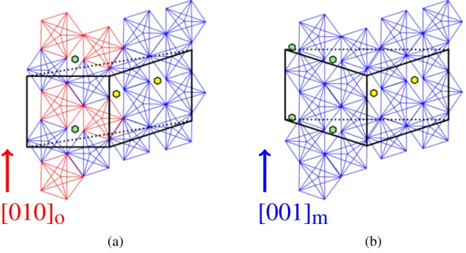
(b)
Figure S1: Structure models of (a) orthorhombic/monoclinic and (b) monoclinic/monoclinic interfaces. Henley clusters are represented with blue and red pentagons; following the same color code as in Fig. 1 of the main document. The orthorhombic and monoclinic cells are drawn in black. The DFT calculation boxes are displayed using dotted black lines.
o-Al
13
Co
4
(010)
o-Al
13
Co
4
(001)
[010]
[001]
Sample’s surface[010]
[001]
Sample’ s surf ace(a)
(b)
Figure S2: Portion of out-of-plane reciprocal space map along [100] at Q = 2.7 ˚A−1 for (a) o-Al13Co4(010) and (b)
for o-Al13Co4(001). These two area of the reciprocal space are the same for o-Al13Co4(010) and o-Al13Co4(001).
The features that are displayed in orange in Fig. 4(b) of the main document can be generated by defects such as dislocations. A simulation of the Fourier transform of a Al13Co4 metadislocation is done to evaluate
this hypothesis. The atomic structure that was used is based on the dislocation model of Heidelmann et al.5 and is displayed in Fig. S3(c). The Fourier transform of such defect is shown in Fig. S3(b) and compared to the experimental measurements Fig. S3(a). This kind of diffraction peaks and diffuse scattering might also be generated by periodically stacked phason planes (related to metadislocations).
−10
−5
0
5
10
0
2
4
L
−10
−5
0
5
10
0
2
4
L
−10
−5
0
5
10
H
0
2
4
L
−10 −5 0 5 10 0 2 4 L −10 −5 0 5 10 0 2 4 L −10 −5 0 5 10 H 0 2 4 LH
−10 −5 0 5 10 0 2 4 L −10 −5 0 5 10 0 2 4 L −10 −5 0 5 10 H 0 2 4 LH
(a)
(b)
(c)
Figure S3: (a) (H,L) out-of-plane reciprocal space maps at K = 3 of o-Al13Co4(010). (b) Simulated out-of-plane maps
at K = 3 : FT simulation of a 23x23x1 orthorhombic cell with a core dislocation in the center of the cell. Features that do not come from the orthorhombic structure are highlighted in red for both figures (a) and (b). Similarities between the measurements and the simulation are observed. (c) Atomic structure of the FT 23x23x1 simulation box : Al and Co atoms are drawn in light blue and dark blue, respectively; the metadislocation core is circled in red.
S2 – o-Al
13Co
4(100) surface models
Figure S4: Surface structure of model P24 (flat surface). Surface Al and Co atoms are drawn in blue and red,
respectively. Subsurface Al and Co atoms are drawn in light blue and orange, respectively.
Figure S5: Surface structure of model P14 (nanostructured surface)). Surface Al and Co atoms are drawn in blue
and red, respectively. Subsurface Al and Co atoms are drawn in light blue and orange, respectively.
S3 – Relaxed Al
13Co
4bulk structures
The crystallographic information (equivalent positions and Wyckoff numbers for monoclinic and orthorhom-bic structures relaxed by DFT) are presented in the following tables. The Al atoms that are present in the center of the Henley clusters are Al15 for m-Al13Co4,6Al16 and Al17 for o-Al13Co4.7
m-Al13Co4(Spage group C2/m, group number 12)6
Lattice parameters
a b c alpha beta gamma
15.18300 8.12200 12.34000 90.0000 107.9000 90.0000 Structure parameters (x,y,z, Wyckoff number and symmetry)
Al11 0.13671 0.21951 0.52149 8j 1 Al10 0.17829 0.27988 0.33435 8j 1 Al7 0.18555 0.28240 0.11092 8j 1 Co5 0.31973 0.20658 0.27779 8j 1 Al13 0.36793 0.28805 0.10985 8j 1 Al14 0.49182 0.26717 0.32987 8j 1 Al4 0.02071 0.00000 0.17091 4i m Co4 0.09742 0.00000 0.01426 4i m Co2 0.09808 0.00000 0.37654 4i m Al15 0.17695 0.00000 0.71842 4i m Al12 0.19447 0.00000 0.22725 4i m Al3 0.25909 0.00000 0.03874 4i m Al5 0.26256 0.00000 0.46521 4i m Co3 0.40945 0.00000 0.01148 4i m Al6 0.41360 0.00000 0.21180 4i m Al2 0.42642 0.00000 0.41972 4i m Al1 0.56605 0.00000 0.17393 4i m Co1 0.58547 0.00000 0.38244 4i m Al9 0.00000 0.24950 0.00000 4g 2 Al8 0.00000 0.00000 0.50000 2c 2/m S-6
o-Al13Co4(Spage group Pmn21, group number 31)7
Lattice parameters
a b c alpha beta gamma
8.15800 12.34200 14.45200 90.0000 90.0000 90.0000 Structure parameters (x,y,z, Wyckoff number and symmetry)
Al25 0.22440 0.29460 0.73520 4b 1 Co4 0.00000 0.77200 0.31670 2a m Al16 0.00000 0.10470 0.23800 2a m Al14 0.00000 0.59860 0.21490 2a m Al17 0.00000 0.41790 0.58810 2a m Al6 0.00000 0.81130 0.15640 2a m Co9 0.22570 0.90990 0.73460 4b 1 Al22 0.22510 0.98100 0.09350 4b 1 Al4 0.00000 0.90850 0.44310 2a m Al24 0.22590 0.58850 0.54220 4b 1 Al19 0.21380 0.90200 0.28310 4b 1 Co3 0.00000 0.19770 0.82500 2a m Al7 0.00000 0.80920 0.83600 2a m Al3 0.00000 0.90530 0.62260 2a m Co2 0.00000 0.09010 0.51140 2a m Co1 0.00000 0.89780 0.00000 2a m Al18 0.21350 0.21380 0.09960 4b 1 Co5 0.00000 0.59860 0.82480 2a m Al15 0.00000 0.71110 0.96680 2a m Al9 0.00000 0.40700 0.85200 2a m Co7 0.00000 0.73090 0.51800 2a m Al26 0.22910 0.42200 0.42520 4b 1 Al21 0.25340 0.25500 0.91720 4b 1 Al13 0.00000 0.52710 0.00540 2a m Al10 0.00000 0.40100 0.14910 2a m Al20 0.24010 0.08290 0.40880 4b 1 Al1 0.00000 0.99450 0.81510 2a m Al2 0.00000 0.09140 0.95690 2a m Al5 0.00000 0.13940 0.67280 2a m Co8 0.00000 0.28770 0.00760 2a m Al11 0.00000 0.68370 0.67490 2a m Al27 0.21330 0.51740 0.73380 4b 1 Al12 0.00000 0.59000 0.39600 2a m Co6 0.00000 0.41190 0.31370 2a m Al28 0.23190 0.27630 0.28490 4b 1 Co10 0.21810 0.59690 0.09840 4b 1 Al8 0.00000 0.25200 0.41400 2a m Al23 0.22140 0.22290 0.55000 4b 1 S-7
S4 – LEED-AFM-STM
c
?
c
?
a
?
a
?
a
a
2
2
??a
a
3
3
??(a) LEED pattern
(b) AFM image
5 μm [100] [001](c) STM image
5 nm [001] [100](1×1)
(1×1)
(2×1)
(2×1)
(3×1)
(3×1)
Figure S6: (a) LEED pattern measured at 30 eV. Diffuse scattering resembling a (2×1) and a (3×1) surface recon-structions are shown in yellow and red arrows, respectively. (b) AFM image of o-Al13Co4(010) (15×15 µm2) showing
a columnar and faceted structure. (c) STM image of a flat terrace at the o-Al13Co4(010) surface (15×15 nm2) at Vb
= 0.6 V. The (1×1), (2×1) and (3×1) cells are drawn in green, yellow and red, respectively. A triangular motif is highlighted in white.
S5 – o-Al
13Co
4(010) and m-Al
13Co
4(¯
201) surface models
Figure S7: Surface structure of model O0. Al and Co atoms are drawn in light blue and dark blue, respectively.
Figure S8: Surface structure of model M3.15. Al and Co atoms are drawn in light blue and dark blue, respectively.
References
(1) Saito, K.; Sugiyama, K.; Hiraga, K. Al13M4-type Structures and Atomic Models of their Twins Mater.
Sci. Eng. A 2000, 294-296, 279–282.
(2) Feuerbacher, M.; Heggen, M. On the Concept of Metadislocations in Complex Metallic Alloys Philos.
Mag. 2006, 86, 935–944.
(3) Heggen, M.; Houben, L.; Feuerbacher, M. Metadislocations in the Structurally Complex Orthorhombic Alloy Al13Co4Philos. Mag. 2008, 88, 2333–2338.
(4) Heggen, M.; Houben, L.; Feuerbacher, M. Plastic-Deformation Mechanism in Complex Solids Nat. Mater.
2010, 9, 332–336.
(5) Heidelmann, M.; Heggen, M.; Dwyer, C.; Feuerbacher, M. Comprehensive Model of Metadislocation Movement in Al13Co4 Scr. Mater. 2015, 98 .
(6) Hudd, R.; Taylor, W. The Structure of Co4Al13Acta Cryst. A 1962, 15, 441.
(7) Grin, J.; Burkhardt, U.; Ellner, M.; Peters, K. Crystal Structure of Orthorhombic Co4Al13J. Alloys
Compd. 1994, 206, 243–247.
![Figure 1: Bulk structure of (a) o-Al 13 Co 4 along the o-[010]](https://thumb-eu.123doks.com/thumbv2/123doknet/14579994.540733/3.918.480.835.271.568/figure-bulk-structure-o-al-o.webp)

![Figure S2: Portion of out-of-plane reciprocal space map along [100] at Q = 2.7 ˚ A −1 for (a) o-Al 13 Co 4 (010) and (b) for o-Al 13 Co 4 (001)](https://thumb-eu.123doks.com/thumbv2/123doknet/14579994.540733/18.918.135.784.100.433/figure-portion-plane-reciprocal-space-map-al-al.webp)