ORIGINAL ARTICLE
Efficiency of a mathematical model in generating
CAD/CAM-partial crowns with natural tooth morphology
Andreas Ender&Werner H. Mörmann&Albert Mehl
Received: 4 August 2009 / Accepted: 12 January 2010 / Published online: 9 February 2010 # Springer-Verlag 2010
Abstract The “biogeneric tooth model” can be used for computer-aided design (CAD) of the occlusal surface of dental restorations. From digital 3D-data, it automatically retrieves a morphology matching the natural surface left after preparation. This study evaluates the potential of this method for generating well-matched and well-adjusted CAD/comput-er-aided manufacturing (CAM) fabricated partial crowns. Twelve models with partial crown preparations were mounted into an articulator. Partial crowns were designed with the Cerec 3D CAD software based on the biogeneric tooth model (Biog.CAD) and, for control, with a conventional data-based Cerec 3D CAD software (Conv.CAD). The design time was measured, and the naturalness of the morphology was visually assessed. The restorations were milled, cemented on the models, and the vertical discrepancy and the time for final occlusal adjustment were measured. The Biog.CAD software offered a significantly higher naturalness (up to 225 to 11 scores) and was significantly faster by 251 (±78)s in designing partial crowns (p<0.01) compared to Conv.CAD software. Vertical discrepancy, 0.52 (±0.28)mm for Conv.CAD and 0.46 (±0.19)mm for Biog.CAD, and occlusal adjustment time, 118 (±132)s for Conv.CAD and 102 (±77)s for Biog. CAD, did not differ significantly. In conclusion, the
biogeneric tooth model is able to generate occlusal morphol-ogy of partial crowns in a fully automated process with higher naturalness compared to conventional interactive CAD software.
Keywords CAD/CAM . Biogeneric tooth model . Cerec . Occlusal surface
Introduction
Reconstructing the occlusion is a major issue in restorative dentistry [1–3]. Although the concepts of occlusion have been discussed controversially over the past decades, it is common consensus that the occlusal design of restorations should stay in harmonic relation to the remaining dentition, and the localization of the occlusal contacts should establish interference-free function of all parts of the stomatognathic system [2–6].
In computer-aided design (CAD)/computer-aided manu-facturing (CAM) dentistry, the occlusion is generated mainly by the CAD software based on a standard morphology [7–12]. However, an automated adaptation process of this standard morphology to an individual clinical defect situation is difficult and fails in many cases leading to manual adaptation of the proposal with design tools. This is a demanding and time-consuming task on the two-dimensional monitor and needs a profound knowledge of CAD software. More recent CAD software uses algorithms to fit the occlusion to static or dynamic bite registration at least for full crowns [12–14].
A fundamental new way to generate dental morphology in CAD/CAM is the“biogeneric tooth model.” It mathematically describes each posterior tooth by reference to a number of specific parameters. The information basis is a 3D-data library
A. Ender (*)
:
W. H. Mörmann:
A. Mehl Division of Computer Restorations,Department of Preventive Dentistry, Cariology, and Periodontology, Center for Dental and Oral Medicine, University of Zürich, Plattenstrasse 11, 8032 Zürich, Switzerland e-mail: [email protected] W. H. Mörmann e-mail: [email protected] A. Mehl e-mail: [email protected] DOI 10.1007/s00784-010-0384-z
of several hundred scans of each posterior human tooth with intact natural and carious-free occlusal surfaces [15]. The biogeneric tooth model extracts all possible features and calculates an average tooth. The deviation of every single library tooth from the average tooth is determined by a principal axis analysis. In this mathematical representation, it is possible to reconstruct a missing surface area by analyzing the remaining tooth substance [15, 16]. As part of CAD software, the biogeneric tooth model offers the possibility for a fully automated design of partial crowns [17–19]. The aim of this study was to investigate this new CAD software with respect to its efficiency generating natural morphology of ceramic CAD/CAM partial crowns.
On this basis, the following hypotheses were tested: does the biogeneric tooth model-based CAD software generate a partial crown (a) faster and (b) with higher naturalness than conventional data-based CAD software and (c) reduce vertical discrepancy and time for occlusal adjustment?
Materials and methods
Natural dentition models and preparation
Twelve patients (six males and six females), aged from 17 to 34 years, with dentitions at least complete with second molars and intact unrestored natural occlusal morphology were selected for the study. They all agreed to participate in the study by informed consent. Plaster replicas, made with type IV gypsum (Dentona Esthetic Gold, Dentona, Dort-mund, Germany) from silicone impressions (Honigum blue, DMG, Hamburg, Germany), were mounted into an articu-lator (Artex TK, AmannGirrbach, Pforzheim, Germany) according to temporomandibular joint relations (Artex facebow system, AmannGirrbach, Pforzheim, Germany) and habitual intercuspidation registrate (R-SI-Line Metal Bite, R-Dental, Hamburg, Germany).
The models were adjusted in order to get the same occlusal contacts as recorded in the mouth with occlusion indicator foil (Hanel foil, Roeko, Langenau, Germany).
For each model set, one molar was randomly chosen for the preparation of a partial crown replacing one cusp and a second molar for a partial crown replacing three cusps not in the same
quadrant or antagonist position, using a random selection program (SPSS 13.1, SPSS Inc., Chicago, IL, USA). Twenty-four preparations were done by three experienced dentists (eight by each of them) following full ceramic preparation guidelines with a minimal thickness of 1 mm at the main fissure line and 1.5 mm at the cusp tips resulting in 12 partial crown preparations replacing one cusp and 12 partial crown preparations replacing three cusps total (Fig.1) [20–22]. Designing the partial crowns
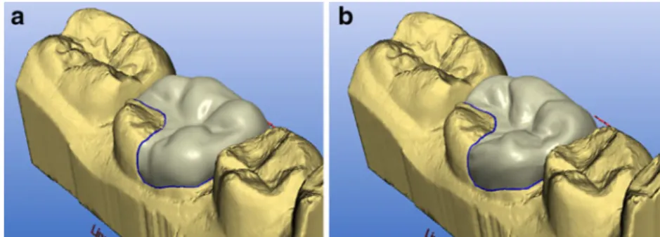
The preparations and the centric bite registrations were scanned using an opto-electronic intraoral camera (CEREC-3D, Sirona, Bensheim, Germany) according to the manu-facturer's instructions. Each partial crown was designed once with a Cerec 3D CAD software v2.80, based on conventional data (Conv.CAD), and once with a Cerec 3D CAD software v3.01, based on the biogeneric tooth model (Biog.CAD) [15, 23, 24], by a Cerec experienced dentist (Fig. 2) [12,20,21].
Manual adjustments were necessary in either mode, however, in biogeneric mode, mainly on the buccal, oral, and proximal surfaces rather than on the occlusal surface. The design time is a measure for the amount of interactive changes. The design parameters of both software versions were set as follows: spacer 20µm, adhesive gap 20µm, virtual grinding −25µm, occlusal contact strength 25µm, and margin thickness 0µm. The restoration was adjusted to get a natural morphology matching to the surrounding situation and three to four occlusal contacts near the centric cusps and central fossa for both software versions. Then, the tool“Virtual Grinding” was activated to set the occlusal contacts to a predefined strength of −25µm before proceeding to the milling process.
For each case, design time was measured from the first activation of a design tool to the end of the adjustment resulting in 24 design times for Biog.CAD and 24 design times for Conv.CAD.
Naturalness of the morphology
The morphologies of the partial crowns were assessed by visual judgment in a double-blind test. For this purpose, the
Fig. 1 Preparation dimension for Cerec 3D restorations (millimeter)
partial crown designs were displayed in pairs on two monitors (A and B), standing side by side (17″ TFT, Coretronic Corp, Hsinchu, Taiwan) connected to one computer. Each partial crown was presented with both designs in random order on the left and right screen. No exterior clue was given with respect to the type of design as seen in Fig.2.
Ten dentists with a long-term clinical experience but no experience in CAD/CAM rated and compared the natural-ness of the morphology of each restoration according to detailed questionnaires (Table1).
Additionally, the overall morphology was rated for both designs according to the criteria “perfect morphology,” “details too weak” (too flat or smooth), and “details too strong” (structure too extreme; Table2).
Vertical discrepancy and adjustment
All partial crowns were machined three times (n=124) from feldspathic ceramic (Vita MKII, Vita Zahnfabrik, Bad Säckingen, Germany) in a CAM unit (Cerec 3 serial no 16284, Sirona, Bensheim, Germany; Fig. 3a, b). The proximal surfaces of the machined partial crowns were adjusted using abrasive discs (Sof-Lex, 3M Espe, Rüs-chlikon, Switzerland) to provide visual perfect seat and the restorations cemented using temporary A-silicon cement (Temposil, Coltène Whaledent, Altstätten, Switzerland).
The vertical increase and the time for the occlusal adjustment was taken for each milled restoration (n=72 for Conv.CAD and n=72 for Biog.CAD) resulting in three values for vertical discrepancy and three adjustment times for each restoration. These three values were averaged to one value for each restoration.
To determine the vertical increase, self-curing acrylic resin material (Duralay, Reliance, Worth, IL, USA) was placed on the incisal plate, and the articulator was closed with the locked pin approaching the plate. The thickness of the acrylic resin
between the tip of the pin and the plate was measured with a dial gauge (1/1,000 mm steps, Tesa YR, Tesa SA, Renens, Switzerland). Occlusal contacts were marked with indicator foil (Hanel 12µm, Roeko, Langenau, Germany; Fig.3, c/cc). Three dentists consecutively did the adjustment with a contra-angle handpiece at 40,000 rpm and a diamond bur (40µm grain, ISO Code 314257514, Intensiv, Lugano, Switzerland). The order of the restorations was random so they were not aware of the design mode of the restoration. The aims were equally distributed occlusal contacts on the restoration and neighboring teeth plus direct contact between the articulator pin and plate (Fig.3, d/dd).
Statistical analysis
To compare the results of design time, vertical discrepancy, and occlusal adjusting time, the dependent sample t test (SPSS 15.0, SPSS Inc., Chicago, IL, USA) was used. The measured values were tested against normal distribution according to the Kolmogorov–Smirnoff test (SPSS 15.0, SPSS Inc., Chicago, IL, USA). The level of significance was set to p=0.05. Statistical differences were tested between one- and three-cusp restorations and between Conv.CAD and Biog.CAD. Correlation between vertical discrepancy and occlusal adjusting time was tested with linear regression analysis and Pearson's correlation coeffi-cient (SPSS 15.0, SPSS Inc., Chicago, IL, USA).
The questionnaires for naturalness concerning fissure relief, occlusal contacts, and cusp shape were analyzed using the Wilcoxon signed-rank test (p=0.01, SPSS 15.0, SPSS Inc., Chicago, IL, USA). Differences concerning the overall rating of the naturalness of the occlusal morphol-ogy generated by Biog.CAD and Conv.CAD were statis-tically analyzed by the Bowker's test (p=0.05) [25]. In this case, the combinations between scores for the biogeneric reconstruction and the scores for the same preparation
Fig. 2 Restoration design of a partial crown replacing three cusps with (a) conventional software and (b) biogeneric design software
A B Equal
Which of both designs offers the more natural fissure morphology?
Which of both has a better or more reasonable occlusal contact point distribution? Which one shows the more natural cusp shape and cusp tip position?
Table 1 Questionnaire to assess the naturalness of the restoration
made with the conventional reconstruction process were summed, and the respective frequencies were recorded in a table (Table 1). Interexaminer reliability was measured with kappa statistics, modified for more than two raters with Fleiss' kappa [26].
Results
No significant differences appeared between one- and three-cusp restorations (p>0.05). Therefore, the data were pooled into the two groups, Conv.CAD and Biog.CAD. The measured values for construction time, occlusal adjustment time, and vertical discrepancy were distributed normal according to the Kolmogorov–Smirnoff test (p<0.05).
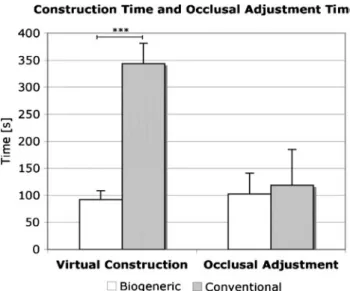
The average design time was 354 (±74) s for the Conv. CAD and 92 (±33)s for the Biog.CAD resulting in a high significant time gain of 251 (±78) s (p<0.001). Figure 4
shows the virtual construction time for Conv.CAD and Biog.CAD.
The occlusal adjustment time, averaged 118 (±132) s for Conv.CAD and 102 (±77)s for Biog.CAD, showed no statistical difference (p>0.05) as seen in Fig. 4. Vertical discrepancy was 0.52 (±0.28) mm with Conv.CAD and 0.46 (±0.19) mm with Biog.CAD with no significant difference (p>0.05). In Fig.5, the vertical discrepancy for both groups is displayed. A correlation between vertical discrepancy and adjusting time did not exist (r=0.08).
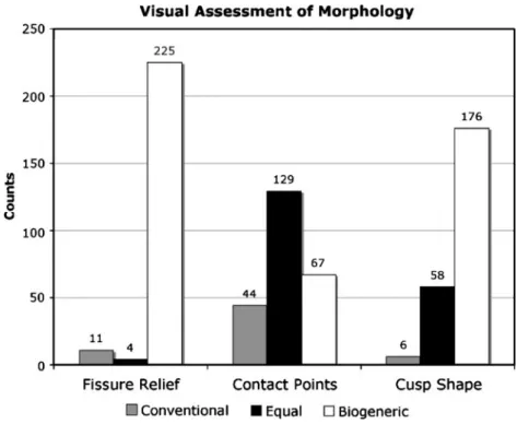
The results of the visual assessment of single morphol-ogy details are shown in Fig.6. For every criteria, a total of 240 scores (24 restorations ×10 dentists) could be achieved. The criteria “fissure relief” and “cusp shape” revealed a highly significant (p<0.001) preference for the morphology created with Biog.CAD with 225 out of 240 scores for fissure relief and 176 out of 240 scores for cusp shape. The criterion “contact points” (occlusal contacts) revealed no statistically significant difference for both groups (p>0.05) with 67 (Biog.CAD) to 44 (Conv.CAD) scores, while 129 scores for equal were given. Kappa values of the interexa-miner reliability ranged from 0.51 (contact points) over
The occlusal morphology for restoration A is The occlusal morphology for restoration B is
Too strong To weak Perfect Too strong Too weak Perfect
Table 2 Questionnaire for overall morphology
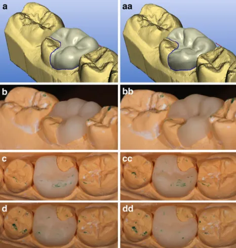
Fig. 3 Processing of one restora-tion with Conv.CAD (a–d) and Biog.CAD (aa–dd) from (a/aa) virtual construction completed, (b/bb) milled restoration, (c/cc) contact points before, (d/dd) contact points after occlusal adjustment
0.59 (cusp shape) to 0.88 (fissure relief), which means moderate and perfect concordance, respectively.
The results of the overall morphology rating are presented in Table 3. The table shows the combination of the scores made in Table2for each restoration. In total, 240 ratings could be made. Two ratings dropped out, as they were not valid. The sum of all fields in one row is the score for Biog.CAD restorations, and the sum of all fields in one line is the score for Conv.CAD restorations. The morphol-ogy created with Biog.CAD was interpreted as perfect (third column of Table3) in almost all cases (197 out of 240), with a highly significant preference (p<0.001), even in those situations, where Conv.CAD was interpreted as imperfect (morphology too flat or too smooth; Table 3, third column, rows 3 and 4), e.g., 66 ratings were made in cases where the morphology was perfect for a reconstruc-tion with Biog.CAD as well as with Conv.CAD for the same preparation (Table 3, column 3, row 3) and 123 ratings for cases which offer a perfect biogeneric
morphol-ogy while the conventional morpholmorphol-ogy was too weak in that case (Table 3, column 3, row 5). The overall interexaminer reliability was substantial (kappa =0.61).
Discussion
An essential step in CAD/CAM fabrication of partial crowns is the design of the occlusal morphology. With conventional design software, this can be time consuming caused by the provided standard morphology, which has to be adapted to the individual tooth with manual interactive design tools. Especially when using a chair-side CAD/ CAM system, like Cerec 3D, any improvement in con-struction time will ease the application in the dental practice.
The results of the present study clearly demonstrated that the Biog.CAD reduce design time of partial crowns by 4 to 5 min, confirming our hypothesis. However, this result was at the low end of the range between 6 and 14 min for the time-saving effect when compared to previous studies where constructions had been done with the Conv.CAD software at the Cerec 3D CAD/CAM system (470 s [11], 446 s [27], and 954 s [28]). The difference can be explained by the fact that in the present study, a highly experienced dentist designed the partial crowns including the manual corrections. This also proves that even highly experienced users will profit from the biogeneric tooth model.
Corrections, if at all necessary, were restricted to proximal surfaces or to the equatorial areas of lingual and buccal surfaces. These are the regions where the knowledge-based biogeneric tooth model is extrapolated with standard mathematical algorithms [16].
The subjective assessment of the partial crown designs resulted in a clear preference for the morphology created with the Biog.CAD, again confirming our hypothesis. The criteria “fissure relief,” “cusp shape and position,” as well as “overall morphology” were all rated better for the biogeneric tooth model. This is worth mentioning because of the automatic calculation of the occlusal morphology
Fig. 4 Mean (±SD) virtual construction times for biogeneric (n=24) and conventional (n=24) partial crown designs and mean (±SD) occlusal adjustment time of biogeneric (n=72) and conventionally (n= 72) designed partial crowns
Fig. 5 Mean (±SD) vertical discrepancy of biogeneric (n= 72) and conventionally (n=72) designed partial crowns
with almost no additional user-interaction. The reason for that certainly is the fact that the biogeneric proposal integrates the natural morphology of hundreds of teeth with a high resolution of details [29]. Nevertheless, the criterion “distribution of occlusal contacts” was rated “equal” with both softwares. Consequently, the automatic-generated occlusal contacts with Biog.CAD were mainly appraised as good as the mainly manual-adjusted occlusal contact points with Conv.CAD.
The vertical discrepancy of the partial crowns (460µm for Biog.CAD and 520µm for Conv.CAD) compared well to the results of other studies (480 and 999µm for Conv.CAD) [11,
27]. In both studies, construction time and vertical increase of Cerec 3D restorations (Conv.CAD) was measured. The measuring procedure was in a similar way (clinical prepara-tion models mounted into an articulator, vertical increase measured at the incisal plate) as the present study. A certain magnification of the real increase should be considered as the measurement was taken at the incisal pin of the articulator. Several factors may lead to vertical discrepancy like errors from scanning and referencing the occlusal
registrate to the preparation, bur geometry, and inaccuracies during fabrication and a certain insecurity of reaching the exact final position on the preparation depending on the fit of the workpieces [31, 32]. Additionally, premature contacts may have been situated close to the occlusal margins of the partial crowns where milling parameters will lead to material excess. Because of the bur geometry, deep fissure lines cannot be grinded entirely by the milling unit. If contacts are located near a deep fossa or fissure line, material excess in this particular region of the milled restoration will lead to vertical increase. This may explain the difference to another study, testing full CAD/CAM crowns where the vertical increase was 15µm at the incisal pin of the articulator [30]. The time needed for occlusal adjusting was not different between the two groups. Thus, the hypothesis that the more natural surface would result in less occlusal adjusting because of their possibly fewer interfering contacts was rejected. The occlusal adjusting time was lower than in the most former in vitro studies with, e.g., 8 [11] and 7 min [27]. Nevertheless, in these studies, the polishing time was included. Another study reported an adjusting time of 17 min [28], but this was in
Fig. 6 Rating scores for fissure relief, occlusal contacts, and cusp shapes generated by Conv. CAD or Biog.CAD. The number of scores is displayed on top of the bars
Overall rating of occlusal morphology
N Biogeneric CAD
Perfect Details too strong Details too weak
Total 197 16 25
Conventional CAD Perfect 72 66 4 2
Details too strong 12 8 3 1
Details too weak 154 123 9 22
Table 3 The frequency of combined scores (n=238) for Biog.CAD and Conv.CAD of partial crown occlusal morphology
vivo, and the dentist has done the intraoral in different space and visibility as in the extraoral situation with the articulator. In the clinical situation, the functional movements of the patient can lead to additional interferences, when only a static bite registrate is used.
No correlation between the vertical discrepancy and the time for occlusal adjustment could be found (r=0.08). In addition to the vertical dimension of a cusp, its position may lead to a premature contact. Using a functionally generated path, registration may further reduce adjusting time, as the freedom in centric and cusp inclines is considered [8,33].
Conclusion
Within the limitation of this study, it can be stated that the biogeneric tooth model provided a quick fully automated proposal of morphologies of partial crowns with high naturalness. Further improvements may be possible in the proximal contact as well as buccal and lingual surfaces, where manual changes are sometimes beneficial. In addition, the implementation of more adult and mature abraded teeth into the biogeneric tooth model would make sense in order to cover a larger variety of older patient's teeth.
Conflict of interest The authors declare that they have no conflict of interest.
References
1. Neff P (1995) Trauma from occlusion. Restorative concerns. Dent Clin North Am 39:335–354
2. Türp JC, Greene CS, Strub JR (2008) Dental occlusion: a critical reflection on past, present and future concepts. J Oral Rehabil 35:446–453
3. Parker MW (1993) The significance of occlusion in restorative dentistry. Dent Clin North Am 37:341–351
4. Gher ME (1998) Changing concepts. The effects of occlusion on periodontitis. Dent Clin North Am 42:285–299
5. Dawson PE (1989) Occlusal therapy. In: Dawson PE (ed) Evaluation, diagnosis, and treatment of occlusal problems. The C.V. Mosby Company, St. Louis, pp 14–17
6. Christensen GJ (2004) Is occlusion becoming more confusing? A plea for simplicity. J Am Dent Assoc 135:767–770
7. Mörmann WH, Brandestini M (1989) Die Cerec computer reconstruction: inlays. Onlays und Veneers, Quintessenz, Berlin 8. Mattiola A, Mörmann WH, Lutz F (1995) The
computer-generated occlusion of Cerec-2 inlays and onlays. Schweiz Monatsschr Zahnmed 105:1284–1290
9. Jedynakiewicz NM, Martin N (2001) Functionally generated pathway theory, application and development in Cerec restora-tions. Int J Comput Dent 4:25–36
10. De Nisco S, Mörmann WH (1996) Computer-generated occlusion of Cerec2 inlays and overlays. In: Mörmann WH (ed) Cad/Cim in aesthetic dentistry, Cerec 10 year anniversary symposium. Quintessence, Berlin, pp 391–407
11. Fasbinder DJ (2006) Clinical performance of chairside Cad/Cam restorations. J Am Dent Assoc 137(Suppl):22S–31S
12. Hartung F, Kordass B (2006) Comparison of the contact surface pattern between virtual and milled Cerec 3D full-ceramic crowns. Int J Comput Dent 9:129–136
13. Reich S, Troeltzsch M, Denekas WM (2004) Generation of functional Cerec 3D occlusal surfaces: a comparison of two production methods relevant in practice. Int J Comput Dent 7:229–238
14. Reich S, Wichmann M, Burgel P (2005) The self-adjusting crown (Sac). Int J Comput Dent 8:47–58
15. Mehl A, Blanz V, Hickel R (2005) Biogeneric tooth: a new mathematical representation for tooth morphology in lower first molars. Eur J Oral Sci 113:333–340
16. Mehl A, Blanz V (2005) New procedure for fully automatic occlusal surface reconstruction by means of a biogeneric tooth model. Int J Comput Dent 8(1):13–25
17. Mörmann WH (2006) The evolution of the Cerec system. J Am Dent Assoc 137(Suppl):7S–13S
18. Richter J, Mehl A (2006) Evaluation for the fully automatic inlay reconstruction by means of the biogeneric tooth model. Int J Comput Dent 9:101–111
19. Dunn M (2007) Biogeneric and user-friendly: the Cerec 3D software upgrade V3.00. Int J Comput Dent 10:109–117 20. Morin MR (2006) Preparation, fabrication and 3D scanning to
achieve esthetic results with chairside Cad/Cam technology. In: Mörmann WH (ed) State of the art Cad/Cam restorations: 20 years of Cerec. Quintessence, Berlin, pp 92–98
21. Hansen S (2000) Preparations for Cerec 3: where are the limits. Int J Comput Dent 3:197–205
22. Cerec Team (2008) Cerec 3D preparations guidelines. Sirona - The Dental Company, Bensheim.http://www.sirona.com/ecomaXL/get_ blob.php?name=cerec_3d_preparation_guidelines_en.pdf. Accessed 30 April 2009
23. Reiss B (2007) Cerec standard 3-D occlusal contouring in comparison with the new biogeneric occlusal morphing: a case report. Int J Comput Dent 10:69–75
24. Reiss B (2003) Occlusal surface design with Cerec 3D. Int J Comput Dent 6:333–342
25. Bortz J, Lienert GA, Boehnke K (2000) Verteilungsfreie Meth-oden in Der Biostatistik. Springer, Berlin p, 929
26. Fleiss JL (1981) The measurement of interrater agreement. In: Fleiss JL, Levin B, Paik MC (eds) Statistical methods for rates and proportions. Wiley, New York, p 321
27. Reich SM, Peltz ID, Wichmann M, Estafan DJ (2005) A comparative study of two Cerec software systems in evaluating manufacturing time and accuracy of restorations. Gen Dent 53:195–198
28. Wurbs M, Simon JF, Troeltzsch M, Denekas T, Wichmann M, Reich S (2006) Dentist-time expenditure for two different adhesive all-ceramic systems. J Dent 34:450–453
29. Mehl A, Blanz V, Hickel R (2005) A new mathematical process for the calculation of average forms of teeth. J Prosthet Dent 94:561–566 30. Fasbinder DJ (2006) Predictable Cerec occlusal relationships. In: Mörmann WH (ed) State of the art of Cad/Cam restorations, 20 years of Cerec. Quintessenz, Berlin, pp 93–100
31. Addi S, Hedayati-Khams A, Poya A, Sjogren G (2002) Interface gap size of manually and Cad/Cam-manufactured ceramic inlays/ onlays in vitro. J Dent 30:53–58
32. Sjogren G (1995) Marginal and internal fit of four different types of ceramic inlays after luting. An in vitro study Acta Odontol Scand 53:24–28
33. Müller H (2006) FGP technique with Cerec 3D. Int J Comput Dent 9:333–338