HAL Id: hal-02548091
https://hal.archives-ouvertes.fr/hal-02548091
Submitted on 20 Apr 2020
HAL is a multi-disciplinary open access
archive for the deposit and dissemination of
sci-entific research documents, whether they are
pub-lished or not. The documents may come from
teaching and research institutions in France or
abroad, or from public or private research centers.
L’archive ouverte pluridisciplinaire HAL, est
destinée au dépôt et à la diffusion de documents
scientifiques de niveau recherche, publiés ou non,
émanant des établissements d’enseignement et de
recherche français ou étrangers, des laboratoires
publics ou privés.
Supporting Model Refinement with Equivalence
Checking in the Context of Model-Driven Engineering
with UML-RT
Raquel Araùjo De Oliveira, Juergen Dingel
To cite this version:
Raquel Araùjo De Oliveira, Juergen Dingel. Supporting Model Refinement with Equivalence Checking
in the Context of Model-Driven Engineering with UML-RT. Model-Driven Engineering, Verification
and Validation Workshop at the MODELS conference (MODEVVA 2017), Sep 2017, Austin, United
States. pp.307-314. �hal-02548091�
Any correspondence concerning this service should be sent
to the repository administrator:
[email protected]
This is a publisher’s version published in:
http://oatao.univ-toulouse.fr/22259
To cite this version: Oliveira, Raquel Araùjo de and
Dingel, Juergen Supporting Model Refinement with
Equivalence Checking in the Context of Model-Driven
Engineering with UML-RT. (2017) In: Model-Driven
Engineering, Verification and Validation Workshop at the
MODELS conference (MODEVVA 2017), 19 September
2017 (Austin, United States)
Official URL
http://ceur-ws.org/Vol-2019/modevva_2.pdf
Open Archive Toulouse Archive Ouverte
OATAO is an open access repository that collects the work of Toulouse
researchers and makes it freely available over the web where possible
Supporting Model Refinement with Equivalence
Checking in the Context of Model-Driven
Engineering with UML-RT
Raquel Oliveira
IRIT and Univ. Toulouse Toulouse, France Email: [email protected]
Juergen Dingel
Queen’s University Kingston, Canada Email: [email protected]Abstract—Through model refinement, system developers can build a system model incrementally and gradually unveil the details of the system. While the process of incrementally building a model can help developers master the complexity of the system, even small modifications to a model may lead to a loss of initially present desirable behavior and properties. Furthermore, the impact of such changes on the model behavior becomes difficult to detect once the model size increases. We propose a formal approach to compare pairs of models in which the second model is the result of an incremental modification of the first. The results have shown that the approach helps verify that the modification is behavior preserving, i.e., that it is a refinement in the sense of the formal methods literature.
I. INTRODUCTION
Model-Driven Engineering (MDE) designates approaches in which models are created to describe a system, and from which a concrete implementation can be derived [9]. MDE provides a means to handle system complexity with abstraction and automation. A model is a representation of what is perceived as the relevant characteristics of the system [23], and it can be used for a variety of purposes such as understanding, communication, analysis, and code generation.
There are limits to the human ability to understand complex-ity [14]. Gradually adding details to the model is one way to master system complexity. MDE development often proceeds by incrementally adding details into the model. One starts with a very high level model in which, e.g., complex states are summarized by just one state, and then, once the developers are satisfied with this high-level model (e.g., certain tests are passed, certain properties are satisfied, etc.), they can unveil this complex state by adding detail to it. It would be helpful for developers to be able to check that these kinds of development steps are behavior preserving, i.e., that the new model is indeed equivalent in some sense to the previous model, because then it may not be necessary to run the same tests again and check that properties are preserved.
Although models aim to abstract system complexity, they can become very complex too, making it difficult to inspect them manually. Such analysis can be done using formal methods, which are techniques strongly rooted in mathematics and which rely on formal models. Formal models are written in
a formal specification language, i.e., a language with a clearly defined and unambiguous semantics. Formal verification tools provide a rigorous way for analyzing a model by exhaustively exploring its state space, which can be used to evaluate the impact when the model changes.
Despite their acceptance, formal techniques are not trivial to use as formal languages are complex to master and to integrate with semi-formal languages. The challenge is to integrate formal techniques with MDE [9], in order to benefit from the rigorousness and automation provided by formal verification tools to support the analysis of non-formal models and to make formal verification amenable to MDE practitioners [29].
Although several approaches have been proposed to bridge this gap using model checking techniques, less attention has been paid to the comparison of models related with each other by an abstraction-refinement relation. This paper proposes an approach based on formal methods to compare UML-RT models in order to show behavioral preservation when one model is the evolution of another one. For this, UML-RT models are automatically translated into a formal specification, and a well-known refinement pattern is implemented using a UML profile. The approach is tool supported and integrated into the Eclipse platform.
II. MDEANDFORMALMETHODCONTEXT This section introduces the main concepts of the MDE language we use in this work, the refinement technique we apply, as well as the formal methods background needed to understand the approach.
A. UML-RT
UML-RT is a language that integrates constructs suitable for modeling complex, event-driven, and potentially distributed real-time systems. A UML-RT model consists of five basic concepts: capsules, ports, protocols, connectors, and state ma-chines (as illustrated in the example of an ATM in Figure 1). Capsules are the central modeling construct of the for-malism. They are used to represent the major architectural elements of real-time systems [27]. Capsules are UMLactive classes with composite structure that communicate through
language. We chose LNT[4] to describe the original models, because LNTand UML-RT have similar features, as described in Section IV-C.
LNTis a language derived from the E-LOTOS[16] standard. It improves LOTOS [15] and can be translated to LOTOS automatically. LOTOS was originally devised to support stan-dardization of OSI (Open Systems Interconnection), but has been used now more widely to model concurrent systems. LNT inherits from LOTOS the way a system is represented: with a data part, based on algebraic abstract data types, and with a control part, based on process calculus. In LNT, both parts (data and control) share a common syntax close to the imperative programming style [10]. In LNT, a system is described by means of blocks of code called modules. Modules can contain types, channels, functions, and processes. A process is an object which denotes a behavior; it can be parameterized by a list of formal gates (or channels), through which the process can communicate with other processes.
LNT it is strongly typed, and types such as int, char, boolean, string, etc. are available. Besides, the language provide constructs such as conditional statements, iteration, assignment, sequential composition, etc. The language can also handle concurrency, communication, non-determinism, signaling, exceptions, etc. An example of a LNTspecification is illustrated in Figure 6 and it will be detailed in the Subsection IV-C.
III. RUNNINGEXAMPLE
To introduce our verification approach, consider a simplified ATM whose model is illustrated in Figure 1. It contains two communicating capsules called UserInterface and Function-alCore, each one containing a state machine modeling part of a transaction validation behavior of an ATM: the user interface models some user interactions with the ATM, and the functional core describes a simplified representation of the validation process of the ATM. The capsules exchange messages through a port, which will trigger state transitions in the corresponding state machine.
The state machine of the FunctionalCore is in the state Idle until a card has been inserted in the ATM (which is detected by the user interface). It triggers the transition to the Validating state, and back to the Idle state. On the UserInterface side, the state machine alternates between the Waiting for validation state and the Done state, according to the messages received from the functional core.
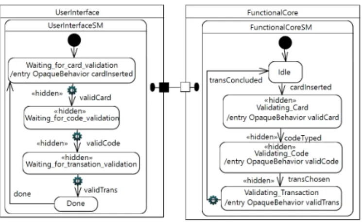
Suppose that developers now want to add more detail to this abstract model by explaining what the complex states Validating and Waiting for validation are, and they produce a new model (Figure 3). In the UserInterface’s state machine, the Waiting for card validation state is activated once a card is inserted in the ATM, staying in this state until the card has been validated by the functional core. Next, the Wait-ing for code validationstate becomes active, followed by the Waiting for transaction validation state once the code has been validated. Once the transaction has been validated, the state machine transits to the Done state, and returns to the
Fig. 3. New ATM model after adding details to the complex states
Waiting for card validation state once a confirmation is re-ceived from the functional core capsule. In the FunctionalCore side, the original Validating state is also further developed to include some details of the validation process.
For the sake of simplicity, the logic for validating the card, the code and the transactions are out of scope of this paper, and we focus on the messages exchanged by the capsules. We do not consider either the case of invalid cards, codes, and transactions. In this context, developers may wonder whether this new version of the model preserves its initial behavior, i.e., whether it is a refinement of the original model.
IV. COMPARINGUML-RT MODELS
Our approach to compare pairs of UML-RT models is illus-trated in Figure 4. The comparison first requires the UML-RT models to be expressed in a formal specification language. With this goal, we wrote an automatic translation from the UML-RT models into LNT formal models using ATL [17] (ATLAS Transformation Language). This step consists of an M2M (model-to-model) transformation, and both the source and the target model should conform to their respective metamodels. Equivalence Checking (CADP) Formal model 2 (LNT) Formal model 1 (LNT) M H UML-RT model 1 (Papyrus-RT) UML-RT model 2 (Papyrus-RT) UML Metamodel UML Metamodel LNT Metamodel (XText) LNT Metamodel (XText) ATL program ATL program Eclipse Platform (SVL) (SVL)
From the formal models, LTSs are automatically generated (i.e., the graphs M and H in Figure 4), which are compared with each other using equivalence checking. Finally, the results of the comparison can be used to modify the original UML-RT models. For instance, if the models are said non-equivalent, an example is generated by the tool. This counter-example identifies why the models are not equivalent, which may help to identify anomalies in the UML-RT models. A transformation from (part of) UML-RT into LNT, and a specification of the LNTmetamodel were implemented in the context of this work.
A. LNT Metamodel
As illustrated in Figure 4, the UML-RT models are con-forming to the UMLmetamodel, whereas for the target model, no metamodel is currently available for the LNT models to be conform with. We specified in XText [7] a subset of the LNT language grammar. As a result, we can assure that the generated LNTspecification is conform to its grammar. B. Modeling the Glass State
In this work we focus on the summary state abstraction pattern [28] (cf. Section II-B). This pattern introduces the concept of glass state, a state containing some states and transitions in the refined version of the model. Our approach allows one to tag some elements in the UML-RT diagrams (states and transitions of the state machine), in order to identify the elements added in the model, and to allow verification that the remaining part of the detailed model behaves exactly as the abstract version of the model.
We use UMLstereotypesin order to identify in the detailed version of the UML-RT models the states and transitions which compose the glass state. Stereotype is a UML concept that permits extending the semantics of UML to a particular domain. Equations 1 and 2 illustrate the idea. The abstract version of the UML-RT model MU M LRTAbs is translated into
a LNT model MLN T using an ATL program P (Equation 1). For the detailed version of the model (Equation 2), the elements of the glass state are first annotated in the model HU M LRTRef using the hidden stereotype. Then, this annotated
model HU M LRTAbs is translated into another model HLN T
using the same ATL program P . Finally, the equivalence checker is used to verify equivalence between MLN T and HLN T. MU M LRTAbs P −→ MLN T (1) HU M LRTRef annotations −−−−−−−−→ HU M LRTAbs P −→ HLN T (2) Figure 3 illustrates the use of the hidden stereotype to tag the states and transitions which compose the glass state in the detailed version of the ATM model. When the ATL program generates the LNTmodel HLN T from this annotated UML-RT model HU M LRTAbs, these annotated elements will generate
special labels in the LNTspecification too. This labeling will be used afterwards by the equivalence checker to ignore these
TABLE I
FROM STRUCTURAL ELEMENTS OFUML-RTTOLNT
UML-RT LNT
capsule module state machine process connector channel
protocol type, channel type
hidden elements and to focus on the remaining parts of the models during the analysis.
The summary state pattern is implemented in this work using the abstraction technique called Omission, introduced in [21]. In this abstraction technique, transitions can be tagged with a special label τ in a state machine, allowing the equivalence verification to bypass these transitions during the analysis.
C. Transforming UML-RT into LNT
The ATL transformations from UML-RT to LNT cover a subset of both languages. Table I illustrates how the main structural concepts of UML-RT are mapped into elements of the LNTlanguage. A capsule in UML-RT becomes a module in LNT, and a state machine becomes a process. A state machine in UML-RT describes the behavioral part of the model, and a process in LNTmainly describes the behavior of the modeled system. Connectors linking UML-RT capsules are translated into LNTchannels through which processes can communicate. Since channels in LNT are typed (to indicate which kind of value is exchanged in the channel), protocols in UML-RT are translated into regular types and channel types in LNT. Regular types allow variables which will receive the messages sent to the channel to be declared.
UML-RT and LNTshare some characteristics regarding the behavioral modeling of systems. In UML-RT each capsule evolves independently and concurrently, exchanging messages with each other from time to time through connectors linking the capsules’ ports. On the other hand, LNT was designed to model asynchronous concurrent systems: systems whose components may operate at different speeds, without a global clock to synchronize them [4]. These processes exchange messages with each other from time to time through channels. In order to translate UML-RT into LNT, UML-RT capsules linked by a connector are translated into LNT by processes whose executions are put in parallel by means of the par-allel composition operator par / end par of LNT. This operator allows one to compose and execute processes in parallel, and to define through which channel the processes communicate.
For the ATM example, the two capsules UserInterface and FunctionalCore (linked by a connector) are expressed in LNT by the parallel composition of two processes: userinterfacesmand functionalcoresm (Figure 5), corresponding to the state machines of the UML-RT capsules in Figure 1. These processes exchange values through the channel ATMProt_connector, of type ATMProt.
Fig. 5. Example of a parallel composition in LNT
In UML-RT, messages received through ports can trigger state transitions, which execute a chain of actions in the model. A chain of actions of a transition is composed of the exit action of the source state (if present), the action code of the transition (if present), and the entry action of the target state (if present). We translate chains of actions into LNTas if-then-else statements for each state of the state machine (lines 10-27 of Figure 6) following the template illustrated in Listing 1. First the transition chain of actions of the initial pseudo state is en-coded, followed by an update of a currentState variable, which keeps track of the current state of the state machine (lines 1-3 in Listing 1). Then an unbounded loop envelops the other transition chain of actions of the state machine (lines 4-20). According to the current state of the state machine (lines 6-19), a series of if-then-else verifies whether the received message (line 5) triggers a transition in the current state (e.g. lines 6-7), and executes the corresponding chain of actions (e.g. lines 8-11).
For this work, the action code of either the exit of a state, the transition, or the entry of a state consists of message-passing actions. For instance, the sending of the message cardInsertedthrough the connector connector in line 10 of Figure 6. More sophisticated action codes with assign-ments or guards are out of scope of this paper and a topic for future work.
Figure 6 illustrates how the body of a state machine is translated to LNT. This LNT specification corresponds to the UserInterfacestate machine of the detailed version of the ATM example (Figure 3). First, an enumerated type containing all
Listing 1. Template of transition chain of actions
1 e x e c u t e a c t i o n c o d e o f e x i t t r a n s . o f i n i t i a l s t a t e 2 e x e c u t e e n t r y a c t i o n o f s t a t e A 3 c u r r e n t S t a t e : = s t a t e A 4 s t a r t l o o p 5 r e c e i v e m e s s a g e t h r o u g h a c h a n n e l 6 i f c u r r e n t S t a t e = s t a t e A 7 i f m e s s a g e R e c e i v t r i g g e r s t r a n s i t i o n A o f s t a t e A 8 e x e c u t e e x i t a c t i o n o f s t a t e A 9 e x e c u t e a c t i o n c o d e o f t r a n s i t i o n A 10 e x e c u t e e n t r y a c t i o n o f t a r g e t s t a t e B 11 c u r r e n t S t a t e : = s t a t e B 12 e l s i f m e s s a g e R e c e i v t r i g g e r s t r a n s B o f s t a t e A 13 e x e c u t e e x i t a c t i o n o f s t a t e A 14 e x e c u t e a c t i o n c o d e o f t r a n s B 15 e x e c u t e e n t r y a c t i o n o f t a r g e t s t a t e C 16 c u r r e n t S t a t e : = s t a t e C 17 e l s i f . . . 18 e l s i f c u r r e n t S t a t e = s t a t e B 19 i f m e s s a g e R e c e i v . . . 20 end l o o p
Fig. 6. State machine coding in LNT
the states of the state machine is declared (lines 3-6). Secondly, a process implements the behavior of the state machine (lines 8-29). The process is parameterized by one channel called connectorof type ATMProt (line 8), corresponding to the connector and the port protocol of the UserInterface UML-RT capsule through which the state machine receives messages. The process contains two variables (line 9), one to receive messages that are sent to the connector channel (line 13), and another one to keep track of the current state of the state machine. Finally, the template described in Listing 1 is implemented (lines 10-27).
A UML-RT state machine receives messages from capsule ports. This is translated to LNTas a non-deterministic choice operator select (lines 13-14 in Figure 6) with one channel called connector (since on the example the capsule has only one port). This operator allows the process to communicate with other processes which synchronize on the same channel, and to receive messages in the variable ATMProt_var.
We acknowledge that ideally it would be good to prove the correctness of the translation. However, this is outside the scope of this work. Instead, we rely on extensive testing and manual inspection.
Such formal specification of a UML-RT model behavior can also have other purposes such as a better understanding of the semantics of UML-RT, which is useful for instance to teach the language.
D. Hiding Elements in the Model
When the UML-RT model is translated into LNT, its hidden elements (e.g., Figure 3) are also labeled in the LNT model with a tag called hidden. Such information is transmitted to the LTSs automatically generated from the formal models, and an SVL[11] (Script Verification Language) program is used to tag the “hidden”-labeled transitions with the special label τ ,
allowing branching bisimulation equivalence to take this into account when comparing the models.
V. TOOLSUPPORT
Figure 4 also illustrates the languages and tools used in our approach. We used Papyrus-RT1[24] for creating the UML-RT models. Papyrus-RT is a domain-specific modeling language tool based on Papyrus, an Eclipse-based environment for UML. Papyrus-RT provides an implementation of the UML-RT modeling language, together with editors, code generator for C++, and a run-time system.
The translation of the UML-RT models into the formal model was done using an program written in ATL2 [17], a model transformation language and toolkit developed on top of the Eclipse platform, which provides ways to produce a set of target models from a set of source models. Sharing both a declarative and an imperative syntax, an ATL transformation program is composed of rules that define how source model elements are matched and navigated to create and initialize the elements of the target models [8].
A grammar of the LNTlanguage was partially defined using XText3 [7], a framework for development of programming languages, allowing one to define languages by specifying its grammar. As a result, XText provides an infrastructure including parser, linker, typechecker, compiler, and editing support for Eclipse, providing a fully featured, customizable Eclipse-based IDE. Once the grammar of a language has been defined with XText, Eclipse can be used as a smart editor for the language, providing the developer with many features such as syntax highlighting, content-assist, auto-completion, folding, and jump-to-declaration [7]. One of the benefits of our approach is that Eclipse can now be used as an editor for LNTspecifications.
CADP4 [13] (Construction and Analysis of Distributed Pro-cesses) is the formal verification toolbox we used. The choice of the toolbox was mainly motivated by its maturity, contin-uous evolution, support, and the numerous tools available. CADP is a toolbox for verifying asynchronous concurrent systems: systems whose components may operate at different speeds, without a global clock to synchronize them. Such components are described by modules, and they communicate through channels. CADPimplements several kinds of analysis: model checking, equivalence checking, reachability analysis, on-the-fly verification, simulation, compositional verification, distributed verification, static analysis, etc. It contains tools to create a graph-representation from the formal model (LTS), and the reasoning is performed over this graph. The more complex the system under evaluation is, the larger its graph will be. CADP handle large graphs using different techniques, such as compositional verification [12]. This technique handle state-space explosion by creating an equivalent graph for each component of the model, replacing a state space by an
1http://www.eclipse.org/papyrus-rt/ 2http://www.eclipse.org/atl/ 3http://www.eclipse.org/Xtext 4http://cadp.inria.fr
TABLE II
CURRENT STATE OF THE FRAMEWORK
Description #loc Details LNTXText grammar 243 27 rules
ATL program 565 18 rules, 11 helpers SVLprogram 8 1 rule
equivalent but smaller one. In practice, bigger models can be handled, so that one can create more realistic models.
In this work, the BISIMULATOR5 [20] and BCG CMP6 equivalence checkers, and the OCIS7 simulator (Open/Caesar Interactive Simulator) are used, the last one for step-by-step simulation with backtracking. Although LNTis the main input language of CADP, the tool supports other input languages such as SVL8 [11] (Script Verification Language). SVLoffers means to describe operations over LTSs, which are difficult to perform by hand on large LTSs. It can be seen as a process calculus extended with operations on LTSs, e.g., minimiza-tion (also called reducminimiza-tion), abstracminimiza-tion, comparison, deadlock detection, as well as orchestration of calls to the CADP tools. The creation of the UML-RT models, the transformation into the formal model, and the editing of the LNT formal model provided by the XText grammar are integrated into the Eclipse platform. This provides a means to build a bridge be-tween the formal verification tool CADPand the model-driven engineering tool Papyrus-RT, allowing the MDE community to benefit from the analyses provided by formal methods tools. Table II illustrates the current state of our verification framework. The XText grammar covers a subset of the LNT language, and the ATL program covers some elements of UML-RT. Finally, the SVL program performs one single transformation in the LTS: hiding the transitions tagged with the hidden label.
VI. VALIDATION
We use this approach to analyze both the abstract and detailed versions of the ATM described in this paper. Both models are created in Papyrus-RT, then the glass state is identified in the detailed model using the hidden stereotype (cf. Figure 3). The ATL transformations generate one LNTmodel for each version of the ATM, with the information about the hidden elements in them. Then, the SVL program hides the elements that are to be hidden in the generated LTSs. Finally, the LTSs of the models are compared with each other using the equivalence checker of CADP.
Specifically, branching bisimulation is used to check whether the abstract version of the model and the detailed one (tagged with hidden elements) are equivalent. The verifi-cation shows that the two models are branching bisimulation equivalent, which means that the detailed version of the ATM model behaves exactly like its abstract version, in the sense of
5http://cadp.inria.fr/man/bisimulator.html 6http://cadp.inria.fr/man/bcg cmp.html 7http://cadp.inria.fr/man/ocis.html 8http://cadp.inria.fr/man/svl.html
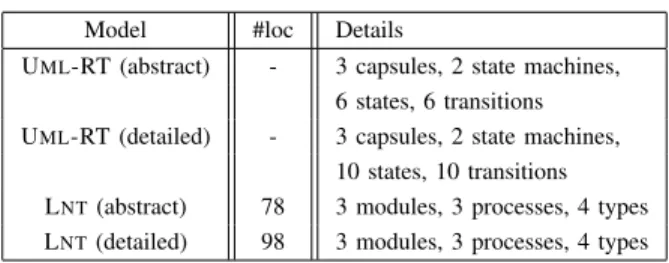
TABLE III RESULTS-SOME FIGURES
Model #loc Details
UML-RT (abstract) - 3 capsules, 2 state machines, 6 states, 6 transitions UML-RT (detailed) - 3 capsules, 2 state machines,
10 states, 10 transitions LNT(abstract) 78 3 modules, 3 processes, 4 types LNT(detailed) 98 3 modules, 3 processes, 4 types
branching bisimulation equivalence relation. In other words, the modifications done to the original model did not change its behavior (disregarding its hidden elements and focusing on the observable behavior of the models), the new version is a refinement of the previous one, and the pattern used to refine the model is the summary state pattern.
Table III illustrates the size of both the source model and the generated target models of the ATM example, and the number of lines of code generated in LNT.
VII. RELATEDWORK
Several approaches [1]–[3], [5], [6], [18], [19], [25], [26], [31] have been proposed to analyze UMLor UML-RT models using formal methods. Some approaches [5], [6], [25], [26] are partially similar to the one presented in this paper. Other approaches are based on UMLprofiles [3], [18], [19], or are supported by different tools [1], [2], [31].
Similar to the Eclipse-based editor for LNT we propose in this paper (as a result of the XText grammar for LNT), an Eclipse-based editor for LOTOS is proposed in [5]. Even though LOTOS and LNTshare some constructs, since LNTis derived from E-LOTOS which enhances LOTOS, an editor for LOTOSwould not be entirely suitable for a LNTspecification. The transformation from UML-RT to LNTpresented in this paper is inspired by some of the ideas presented in [6], [25], [26]. In [6] the authors present a translation from UML-RT to CSP (Communicating Sequential Processes), a process algebra formalism which shares some constructs with LNT such as the representation of system behavior by processes. This work inspired our own translation to LNTin some aspects; however, our work is specific to LNT. On the other hand, in [26] (resp [25]), the formal semantics of UML-RT is defined using the OhCircus (resp kiltera) formalism, which helped us to better understand the semantics of UML-RT before mapping some of its elements into LNT.
Closer to our work, AVATAR [18] is a SysML environment defined to take into account both security and safety properties in graphical models, and to automatically prove both kinds of properties from the system models. It does not cover, however, equivalence verification of models. Alternatively, DIPLODOCUS [19] is a UMLprofile intended for the mod-eling and the formal verification of real-time and embedded applications. However, DIPLODOCUS mainly focuses on im-plementing architectural elements (e.g., CPUs, bus, memories) of the embedded applications, while our concern is mainly
with the behavior of the system. Finally, TURTLE [3] (Timed UML and RT-LOTOS Environment) is a UML 1.5 profile dedicated to the modeling and formal verification of real-time systems. Its main strength lies on its formal semantics defined in a variation of LOTOS: RT-LOTOS. However, it does not seem that the approach has been applied to equivalence verification either.
In TTool [2] (the Turtle Toolkit), UML models may be automatically transformed into a LOTOSspecification, in order to evaluate properties of the system by model checking. TTool is an open-source toolkit that supports several UML2 / SysML profiles, including TURTLE and DIPLODOCUS. Alternatively, CTTool [1] can generate LOTOS specifications that implement a (synchronous) semantics of UML2 compo-nent diagrams and state-machines, and analyze this LOTOS code with CADP. CTTool provides a number of menus for controlling the CADPfunctions. However, the approach mainly focuses on distributed components, while our work focuses on real-time systems, and targets the LNTlanguage. Another tool-supported approach is provided in [31], which also uses ATL to translate UML-RT into a formal notation, here, functional finite state machines. However, the focus of the formal analysis is on symbolic execution and model checking.
In summary, the advantage of our work compared with the previous work is that our approach benefits from equivalence checking to compare UML-RT models and to verify behavior-preserving refinement between models, with the ultimate goal of providing better support to MDE developers. Besides, while previous work mainly targets the LOTOS language, we cover the LNT language and provide a syntax-highlighting Eclipse editor for LNTdevelopers.
VIII. CONCLUSION
In this paper we propose an approach to support model refinement, i.e., the process of gradually adding details to the model in an incremental development. Our approach provides a framework to verify whether this process preserves the model behavior. With this goal, the initial model and its detailed version are first translated into two formal models, and later compared with each other using equivalence checking.
The contributions of the paper are: (a) the use of equivalence checking to support the verification of behavioral-preserving refinement in the MDE context; (b) an automatic translation from UML-RT into the LNT formal language, which relieves practitioners from having to be familiar with the formal language; (c) the implementation of the summary state pattern, which is a first step to automatize the verification of the pattern catalog proposed in [28]; (d) the integration of Papyrus-RT (an MDE tool) with CADP(a formal verification tool), making formal methods more accessible to non-experts in the domain; and finally (e) the approach is tool supported.
The approach has been validated by the application in two case studies: First, in a PingPong model, in which two capsules (Pinger and Ponger) exchange messages with each other. Secondly, in the ATM example described in this paper, in which the summary state pattern has been implemented and
an abstract and a detailed versions of the model are compared with each other. Equivalence between the models has been shown, which means that the detailed version of the model is a refinement of the abstract one.
We plan to improve the readability of the counter exam-ples in case of non-equivalent models, since these counter examples are expressed as states and transitions of the formal specification, making it hard to identify to which states and transitions they correspond in the original UML-RT models. We also plan to investigate the potential use of the simulation tools of CADPto simulate UML-RT models. Besides, a plugin could be developed to invoke the CADP tools directly from Eclipse. CADP provides both a graphical user interface and a command line interface that can be easily integrated within Eclipse. Finally, a natural improvement would be to enlarge the coverage of the UML-RT language, and to implement other patterns of the catalog in [28]. For this, enhancements in the LNT grammar and in the ATL transformations would be necessary.
ACKNOWLEDGMENT
The authors would like to thank Hubert Garavel, researcher at INRIA Rhˆone-Alpes, for his support and advice during the development of this work
REFERENCES
[1] S. Ahumada, L. Apvrille, A. Cansado, E. Madelaine, E. Salageanu, et al. Specifying Fractal and GCM components with UML. In SCCC’07, pages 53–62. IEEE, 2007.
[2] L. Apvrille. TTool, an open-source toolkit for the modeling and verification of embedded system. http://ttool.telecom-paristech.fr/, 2005. [Online; accessed 22-January-2017].
[3] L. Apvrille, J.-P. Courtiat, C. Lohr, and P. de Saqui-Sannes. Turtle: A real-time uml profile supported by a formal validation toolkit. IEEE transactions on Software Engineering, 30(7):473–487, 2004.
[4] D. Champelovier, X. Clerc, H. Garavel, Y. Guerte, C. McKinty, V. Powazny, F. Lang, W. Serwe, and G. Smeding. Reference Manual of the LNT to LOTOS Translator (Version 6.1). INRIA/VASY and INRIA/CONVECS, 131 pages, 2014.
[5] G. De Ruvo and A. Santone. An Eclipse-based Editor to Support LOTOS Newcomers. In WETICE’14, pages 372–377, 2014.
[6] G. Engels, R. Heckel, J. M. K¨uster, and L. Groenewegen. Consistency-preserving model evolution through transformations. In UML’02, pages 212–226, London, UK, 2002. Springer-Verlag.
[7] M. Eysholdt and H. Behrens. Xtext: Implement your language faster than the quick and dirty way. In Proceedings of the ACM International Conference Companion on Object Oriented Programming Systems Lan-guages and Applications Companion, OOPSLA ’10, pages 307–309, New York, NY, USA, 2010. ACM.
[8] T. E. Foundation. ATL - a model transformation technology. http: //www.eclipse.org/atl/, 2009. [Online; accessed 20-January-2017]. [9] R. France and B. Rumpe. Model-driven development of complex
software: A research roadmap. In 2007 Future of Software Engineering, FOSE ’07, pages 37–54, Washington, DC, USA, 2007. IEEE Computer Society.
[10] H. Garavel. Revisiting sequential composition in process calculi. Journal of Logical and Algebraic Methods in Programming, 2015.
[11] H. Garavel and F. Lang. SVL: A Scripting Language for Compositional Verification, pages 377–392. Springer US, Boston, MA, 2002. [12] H. Garavel, F. Lang, and R. Mateescu. Compositional verification of
asynchronous concurrent systems using cadp. Acta Informatica, pages 1–56, 2015.
[13] H. Garavel, F. Lang, R. Mateescu, and W. Serwe. CADP 2011: A Tool-box for the Construction and Analysis of Distributed Processes. Interna-tional Journal on Software Tools for Technology Transfer, 15(2):89–107, 2013.
[14] P. Hallinger, D. P. Crandall, and D. N. F. Seong. Systems Think-ing/Systems Changing & A Computer Simulation for Learning How to Make School Ssmarter. Advances in Research and Theories of School Management and Educational Policy, 1(4):15–24, 2000.
[15] ISO/IEC. Lotos — a formal description technique based on the temporal ordering of observational behaviour. Draft International Standard 8807, International Organization for Standardization — Information Process-ing Systems — Open Systems Interconnection, Geneva, July 1987. [16] ISO/IEC. Enhancements to LOTOS (E-LOTOS). International Standard
15437:2001, International Organization for Standardization — Informa-tion Technology, Geneva, Sept. 2001.
[17] F. Jouault and I. Kurtev. Transforming models with atl. In Proceedings of the 2005 International Conference on Satellite Events at the MoDELS, MoDELS’05, pages 128–138, Berlin, Heidelberg, 2006. Springer-Verlag. [18] D. Knorreck, L. Apvrille, and P. de Saqui-Sannes. TEPE: A SysML Lan-guage for Time-constrained Property Modeling and Formal Verification. SIGSOFT Softw. Eng. Notes, 36(1):1–8, 2011.
[19] D. Knorreck, L. Apvrille, and R. Pacalet. Formal system-level design space exploration. Concurrency and Computation: Practice and Expe-rience, 25(2):250–264, 2013.
[20] R. Mateescu and E. Oudot. Bisimulator 2.0: An on-the-fly equivalence checker based on boolean equation systems. In Proceedings of the 6th ACM-IEEE International Conference on Formal Methods and Models for Codesign MEMOCODE’2008 (Anaheim, CA, USA), pages 73–74. IEEE Computer Society Press, June 2008.
[21] R. Oliveira, S. Dupuy-Chessa, and G. Calvary. Equivalence Checking for Comparing User Interfaces. In EICS’15, pages 266–275, New York, USA, 2015. ACM.
[22] D. Park. Concurrency and Automata on Infinite Sequences. In GITCS, pages 167–183. Springer-Verlag, 1981.
[23] J. L. Peterson. Petri Net Theory and the Modeling of Systems. Prentice Hall PTR, Upper Saddle River, NJ, USA, 1981.
[24] E. Posse. Papyrusrt: Modelling and code generation (invited presenta-tion). In Proceedings of the International Workshop on Open Source Software for Model Driven Engineering co-located with (MODELS 2015), Ottawa, Canada, September 29, 2015., pages 54–63, 2015. [25] E. Posse and J. Dingel. An executable formal semantics for UML-RT.
Software & Systems Modeling, 15(1):179–217, 2016.
[26] R. Ramos, A. Sampaio, and A. Mota. Rigorous development with UML-RT. Master’s thesis, Federal University of Pernambuco, 2005. [27] B. Selic. Using UML for modeling complex real-time systems. In
LCTES’98, pages 250–260. Springer, 1998.
[28] B. Selic. A short catalogue of abstraction patterns for model-based software engineering. Int. J. Software and Informatics, 5(1-2):313–334, 2011.
[29] B. Selic. What will it take? A view on adoption of model-based methods in practice. Software and System Modeling, 11(4):513–526, 2012. [30] R. J. van Glabbeek and W. P. Weijland. Branching Time and Abstraction
in Bisimulation Semantics. Journal of the ACM, pages 555–600, 1996. [31] K. Zurowska and J. Dingel. A customizable execution engine for models of embedded systems. In BM-FA 2009-2014, Revised Selected Papers, pages 82–110, 2014.

![Figure 4 also illustrates the languages and tools used in our approach. We used Papyrus-RT 1 [24] for creating the U ML -RT models](https://thumb-eu.123doks.com/thumbv2/123doknet/14414910.512459/8.918.516.798.114.189/figure-illustrates-languages-tools-approach-papyrus-creating-models.webp)