Cost Reduction of Polar Class Vessels:
Structural Optimization that Includes Production Factors
by
Stephen S. Normore
B.Eng., Ocean and Naval Architectural Engineering, Memorial University of Newfoundland and Labrador, 2007
Submitted to the Department of Mechanical Engineering and the Engineering Systems Division in Partial Fulfillment of the Requirements for the Degrees
of
Masters of Science in Naval Architecture and Marine Engineering, and
Masters of Science in Engineering and Management
ARCHN
at the MASSACHUSETTS INS E
OFTECHNOLOGY
Massachusetts Institute of Technology
JUN
2
5 2013
June 2013
© 2013 Stephen S. Normore. All rights reserved
ARIES
The author hereby grants to MIT permission to reproduce and todistribute publicly paper and electronic copies of this thesis document in whole or in part in any medium now known or hereafter created.
Signature of Author_
Department of Mechani I Enginer an ngineering Systems Division
/ May 10, 2013)
Certified by
Daniel D. Frey Professor of anical Engine ring and Engineering Systems
Khesis Supervisor
Accepted by__ _ __Hale
Pat Hale Director, Systems Design and Management Fellows Program EpginjpygSys~te Division
Accepted by W
David E. Hardt Chair, Departmental Committee on Graduate Students Department of Mechanical Engineering
Cost Reduction of Polar Class Vessels:
Structural Optimization that Includes Production Factors
by
Stephen S. Normore
Submitted to the Department of Mechanical Engineering and the Engineering Systems Division on May 10, 2013 in Partial Fulfillment of the requirements for the Degrees of
Masters of Science in Naval Architecture and Marine Engineering and
Masters of Science in Engineering and Management
Abstract
The design of ship structures was normally optimized to reduce construction material and maintain adequate strength while adhering to a given classification society's rules. In the case of Polar Class vessels, where weight minimization was important, higher fabrication labor costs occurred due to the closely spaced frames and thicker material needed. There was a cost trade-off between minimizing material under the traditional design method and designing a ship that was easier to construct at the
shipyard, i.e. designing for downstream processes.
Using the newly defined Unified Requirements for Polar Ships by the International Association of Classification Societies Inc., a numerical tool was developed to minimize construction cost of the icebreaker's hull form. This tool allowed the user to tailor the labor and material metrics to represent a specific shipyard. The tool then specified an optimum structural solution in terms of minimum weight and production cost.
Thesis Supervisor: Daniel D. Frey
Acknowledgements
This thesis would not have been possible without the guidance and support of so many organizations and individuals who helped the author achieve its completion. As such, the author would like to express his sincere appreciation to the following:
- Vanessa Normore for her love, devotion, and unwavering support to the author in helping to remove any distraction and allowing him to focus on his
studies while at MIT,
Dr. Dan Frey for his support and guidance in the development of the optimization program and completion of this research,
* Douglas Jonart for his assistance with reviewing and editing this paper,
e Pat Hale for his guidance with the SDM program and paving the way for
so many individuals to experience such a wonderful and educating curriculum,
e Philip Koening for his intricate knowledge of ship production and
providing invaluable information to the author during the beginning months of research,
- Dr. Jeff Beach for his openness and willingness with to provide information regarding production based cost estimating,
e Laurent Deschamps for providing fundamental information that without,
the author would not have been able to complete his research,
e Dan McGreer and Wade Carson with STX Canada Marine for their
contribution of information regarding weight based cost metrics for icebreakers,
e Dan Vyselaar and John Shaw with Seaspan Marine -Vancouver Shipyards
for his assistance with outlining methods of production cost estimation for icebreakers,
e Dr. Claude Daley for his approachable demeanor and eagerness to always
assist in any way possible,
- John Dolny with ABS for his intricate knowledge of the Steel Vessel Rules used in the development of the program, and last but not lease,
e George Solis with NASSCO for his collaboration with developing the
Table of Contents
Acknowledgem ents ... 5 Table of Contents... 6 Table of Figures ... 8 1.0 Introduction... 10 2.0 Background ... 122.1 Countries Operating Ice-capable Ships... 12
2.2 Icebreaking Process ... 13
2.3 Classification of Ice Type ... 15
2.4 Icebreaking Hull Form s ... 16
2.4.1 Hull Form Geom etry Nom enclature ... 16
2.4.2 Developm ent of Icebreaking Hull Form s ... 18
2.5 Structure of Ice-Capable Ships ... 22
2.5.1 Hull Structure N om enclature ... 22
2.5.2 Icebreaking vs. Ice-strengthened Vessels ... 24
2.6 Developm ent of Polar Code... 26
2.6.1 Classification Societies ... 26
2.6.2 IACS and the Polar Code ... 27
2.6.3 IACS, ABS, and the Polar Code ... 31
2.7 Current M ethod of Design ... 33
2.8 M otivation of Thesis... 35
2.8.1 Developm ent of Research Concept... 35
2.8.2 Current Cost Estim ation Techniques ... 36
3.0 Program Developm ent... 41
3.1 Goal of Program ... 41
3.2 Initial Program Setup ... 42
3.3 Optim ization Setup ... 44
3.4 A ssum ptions... 46
3.4.1 General A ssum ptions ... 46
3.4.2 Costing A ssum ptions ... 47
3.4.3 Structural Assum ptions... 50
3.5 Test Hull U sed ... 52
4.0 Program Description ... 53
4.1 User Inputs and Variable Assignment Description... 55
4.1.1 U ser Inputs ... 55
4.1.2 Calculate Region Pressures... 59
4.2 Optimization Setup and Run Loop Description... 60
4.2.1 Set-up of Bounds and Initial Guess ... 60
4.2.2 Set Optimization Algorithm Options ... 60
4.2.3 Run Loop Optimization Routine... 61
4.3 Program Output Description... 62
4.3.1 Determine Best Solution ... 62
4.3.2 Round-up Design Variables...63
4.3.3 Output / Display Solution ... 63
5.0 Results, Discussion, and Validation... 66
5 .1 R esults... . 66
5.1.1 Mild Steel Results ... 67
5.1.2 Grade-32 High Strength Steel Results ... 70
5.2 Discussion of Results... 72
5.2.1 Metrics Used and Concern with Cost Scale... 72
5.2.2 Cost versus Weight Trade-off... 73
5.2.3 Bow Frame Spacing ... 74
5.2.4 Upper and Lower Bounds ... 75
5.2.5 Sensitivity Analysis ... 76
5.2.6 Family of Solutions... 76
5.3 Validation of Program... 76
6.0 Areas for Future W ork & Program Development... 78
7.0 Conclusions... 81
B ib lio gra p h ... 82
Appendix A List of Acronyms ... 84
Appendix B Program Code ... 85
Section 1 Main Program ... 85
Section 2 Production Cost Objective Function... 103
Section 3 W eight of Material Objective Sub-Function... 104
Section 4 Cost of Labor Objective Sub-Function ... 106
Section 5 Constraints ... 114
Appendix C Hull Form Geometry Used in Calculations ... 121
Appendix D Production Metrics Used in Calculations ... 123
Table of Figures
Figure 1: Concept of a Ship's Hull Breaking Ice ... 13
Figure 2: Depiction of Ice Being Submerged Under a Vessel... 13
Figure 3: Picture of Typical Broken Ice Flows... 14
Figure 4: Depiction of Glancing Impact of Ice on Hull Forms ... 14
Figure 5: Ice Categories and Typical Thickness Range ... 15
Figure 6: Development of Sea Ice and Classification... 16
Figure 7: Hull Geometry Terms for Hull Bows... 16
Figure 8: Categories of Icebreaking Hull Forms ... 19
Figure 9: Evolution of Ice Breaker Hull Forms Identifying Specifically the "White bow" and the "Spoon Bow"... 20
Figure 10: Evolution of Ice Breaker Hull Forms Identifying Specifically the "F lat F am ily"... 20
Figure 11: Bow Picture of Polar Sea... 21
Figure 12: Side Picture of Polar Sea ... 21
Figure 13: Bow Picture of Oden ... 21
Figure 14: Side Picture of Oden ... 21
Figure 15: Depiction of Structural Members of Hull Forms ... 23
Figure 16: Depiction of Simple Transversely and Longitudinally Framed Hulls ... 24
Figure 17: Depiction of Strengthened Structure for "Ice-strengthened" Vessels... 25
Figure 18: Depiction of Strengthened Structure for Icebreakers ... 26
Figure 19: IACS Polar Classes and Descriptions ... 29
Figure 20: Defined Regions for Strengthening of Polar Class Hull Forms... 30
Figure 21: ABS Notations for Vessels that Operate in Ice ... 32
Figure 22: Typical Icebreaker Hull Form Structure ... 33
Figure 23: Typical Design Process for Ice Class Vessels... 34
Figure 24: Example of SWBS Format... 37
Figure 25: Example of PWBS Format ... 37
Figure 26: Illustration of a Plate with an Attached Frame... 48
Figure 27: Illustration of Intermediate Frames ... 51
Figure Figure Figure Figure 29: 30: 31: 32:
Flow Chart of Program ... 54 Illustration of Program's Run Loop Optimization Routine ... 62
Exam ple of Program Output ... 64 Weight Vs. Polar Class For Comparison of Both Optimization
M ethods using M ild Steel... 67
Cost Vs. Polar Class For Comparison of Both Optimization Methods
using Grade-32 High Strength Steel... 68
Cost Savings Vs. Weight Increase for Production Cost Minimization
compared to Weight Minimization using Mild Steel... 69
Weight Vs. Polar Class For Comparison of Both Optimization
Methods using Grade-32 High Strength Steel... 70
Cost Vs. Polar Class For Comparison of Both Optimization Methods
using Grade-32 High Strength Steel... 71
Cost Savings Vs. Weight Increase for Production Cost Minimization compared to Weight Minimization using Grade-32 High Strength
S teel... . . 7 1
Base W elding Cost M etrics Used... 72
Fram e Spacing Factor U sed ... 72
Frame Spacing for Polar Class 1 Identifying a Larger Bow Frame
Spacing than the Bow Intermediate Region ... 75 Figure 33: Figure 34: Figure 35: Figure 36: Figure 37: Figure Figure Figure 38: 39: 40:
1.0
Introduction
Traditionally, the first step of ship design has been for the owner to choose a classification society, prescribing the rules to which his or her vessel will adhere. Next, the design firm would create a vessel that both met the owner's desires and complied with existing standards and regulations. In this phase, the design of a vessel was normally optimized to reduce the amount of material for the vessel's hull form without compromising strength. When completed, the vessel's design was then given to a shipyard where the ship was to be constructed. The shipyard alone determined the true costs associated with material, labor, overhead, and profit, most often transferring them to the owner.
An interesting aspect of this traditional method would arise when, for example, a disconnect developed between the engineering firm's design and the construction methods used at the shipyard for fabrication of the vessel. One possible scenario that might have developed involved the design, optimized by the design firm to have increased strength and minimum material, forcing the shipyard to procure a particularly high strength material uncommon to the work force. The resulting cost increase with material and labor identified one way by which optimization in one phase could negatively impact later design/construction phases.
In the cases of ice-class or Polar Class vessels, with strengthened hull structure for operation in ice-covered water or in the polar regions of the globe, these disconnects could be even greater. However, instead of the disconnect being with material and strength, it often developed between the density of hull structure in the design phase and the labor effort expended during the construction phase. This was due to the fact that ice-class and Polar Class vessels have more strengthening structure in a given foot print area compared to an open-water hull form not intended to come in contact with ice. The high density of the structure reduced the accessibility for welders to easily access joints for welding. Therefore extra effort was expended, resulting in higher labor costs to the shipyard, and ultimately to the owner of the vessel.
To determine the true impact of this additional labor cost a trade-off analysis was completed. More specifically, the trade-off between the cost obtained when minimizing materials and the cost obtained when designing a more easily produced ship was conducted for ice-capable vessels. Therefore the concept of design for downstream practices was researched and applied to develop a method to optimize, at a global level, the construction costs of an ice-class or Polar Class hull form by minimizing total costs (including costs of production) and compare it to the cost obtained by only minimizing material.
2.0
Background
2.1 Countries Operating Ice-capable Ships
Not surprisingly, the prominent activity of ships operating in ice-covered waters has come from northern countries that either needed access to the Arctic or that have territorial waters that become ice-covered at least part of the year. Consequently, Canada, the United States, Russia, Norway, Finland, and Sweden have been the nations that have contributed the most to icebreaking technology. Due to variations in geography and needs for operating vessels in ice, the countries have provided various levels of progress to ice-capable vessel designs. Finland and Sweden, where parts of the coastline have become frozen for certain periods thought-out the year and are ice-free for the remainder, have needed to maintain open access to their ports for shipment of goods only when ice was present, using lower class icebreaking vessels. Canada and the United States had similar issues with winter freezing of the Great Lakes closing off access to certain ports. They too have operated icebreakers to grant access where needed, predominately more so Canada than the United States. These two countries, along with Russia, have additionally operated bigger and more capable ships in the Arctic Ocean, dealing with thicker ice to aid northern coastline ports that become ice-locked.
Since the early 1900's, Russia has held the largest number of vessels that are ice-capable - followed by Sweden and Finland, given their necessity of coastline access year round. Depending on the period of research, Canada has maintained the next largest number of ice-capable/icebreaking vessels.
2.2 Icebreaking Process
Generally speaking, as an icebreaker advances, the ice in front of the vessel would begin to bend below its level position on the water surface and become pushed under the ship's hull form. Eventually a point of failure/fracture would occur at some distance forward of the ship's bow leaving a broken piece of ice that would either be pushed to the side of the vessel or would flow underneath the vessel, depending on the bow geometry. This process continued as the vessel maintained its forward motion. Figure 1 identifies this fundamental icebreaking process. Figure 2 illustrates how ice can be submerged under the hull if it was not pushed to the side of the vessel.
Figure 1: Concept of a Ship's Hull Breaking Ice
N spray
Source: C. G. Daley, lecture on ship-ice interaction (Ice Engineering, course taught at Memorial University of Newfoundland and Labrador, St. John's, NL, 2007), Slide 11.
Figure 2: Depiction of Ice Being Submerged Under a Vessel
Source: C. G. Daley, lecture on resistance & powering (Ice Engineering, course taught at Memorial University of Newfoundland and Labrador, St. John's, NL, 2007), Slide 5.
Besides the direct process of breaking ice, there were other methods that bring a vessel in contact with ice. The second most notable method was when a vessel was operating in ice that was not heavy packed, but had open areas of water visible on the surface such as shown in Figure 3. When a vessel was transiting in this type of ice flow, the "glancing" impacts of ice would hit the ship's hull as it advances. Depending on the
speed of advance of the ship, the impact could produce significant pressures that the hull must withstand. Figure 4 illustrates how typical glancing ice would impact a vessel during a transit.
Figure 3: Picture of Typical Broken Ice Flows
Source: Transport Canada (website), accessed April 4, 2013, http://www.tc.gc.ca/eng/marinesafety /debs-arctic-shipping-operations-ice-navigators-1708.htm.
Figure 4: Depiction of Glancing Impact of Ice on Hull Forms
Source: C. G. Daley, lecture on structural loads (Ice Engineering, course taught at Memorial University of Newfoundland and Labrador, St. John's, NL, 2007), Slide 12.
These ice interactions required the hull to absorb significant amounts of energy without failing, and experience had shown that hull geometry was one of the most important factors to consider in designing a successful hull form. Over the past century, as more knowledge was gained with ship-ice interactions, hull forms evolved to be more effective.
thick
msive
2.3 Classification of Ice Type
In much the same way that a nation's geography dictated its vessels' ice capabilities in Section 2.1, a specific vessel's capability were dictated by different environmental aspects of its intended operation. The most important of these aspects would be the type of sea ice the vessel was expected to encounter. As such, there was a defined classification system for ice and the typical thickness that was representative of that type, found in Figure 5.1
Figure 5: Ice Categories and Typical Thickness Range
Typical Ice General Category Sub-Category of Ice Thickness Range
of Ice [cm]
New Ice Nilas 5- 10
Young Ice Grey 10- 15
Young__Ice Grey-White 15-30
Thin First Year, First Stage 30 - 50 Thin First Year, Second Stage 50- 70
First Year Ice Medium First Year 70 - 120
Thick First Year >120
Second Year
-Multiyear
-A depiction of the major categories of ice can be found in Figure 6 below, and it
is worth noting the formations referred to by the terms rafting, compression ridges, consolidation and hummocks for later discussion.
Figure 6: Development of Sea Ice and Classification
Source: C. G. Daley, lecture on physical properties of ice (Ice Engineering, course taught at
Memorial University of Newfoundland and Labrador, St. John's, NL, 2007), Slide 10.
2.4 Icebreaking Hull Forms
2.4.1 Hull Form Geometry Nomenclature
Key to the discussion of hull form development was the understanding of the terminology used to describe hull forms. Figure 7 identifies the most notable aspects of hull form geometry with respect to the bow.
Figure
7:
Hull Geometry Terms for Hull Bows
Source: Thomas Lamb, Ship Design and Construction, 2 vols. (Jersey City, NJ: The Society of Naval
When one was looking to develop an icebreaking hull, there were many aspects to discuss. The buttock, waterline, and flare angles defined how the hull form would impact ice and subsequently absorb/distribute the energy required to break and move the ice out of the vessel advancing. As such, these three were the most important to know for the purpose of this paper, and each of these angles are defined below.
1. The buttock angle defined the angle between the water surface and the hull bow when looking at the profile view (side view) of the ship,
2. The waterline angle defined the angle between the hull bow and an invisible line that extends parallel to the mid-body ship's side when looking at the plan view (top view) of the ship, and
3. The flare angle defined the angle between the water surface and the hull bow when looking at the body view (front view) of the ship.
The remaining terms in the figure worth explaining are:
1. The stem angle defined the buttock angle that was located at the most forward part of the bow,
2. The ice foot defined the structure used to prevent the vessel from completely riding up onto the ice to a point where the vessel could no longer free itself by going astern, and
3. The clearing wedge defined the structure used to prevent submerged ice from flowing along the bottom of the vessel as it advanced, and instead be pushed the to the side so it may rise to the surface. This would inherently protect the propellers in the stern of the ship as it moved forward.
2.4.2 Development of Icebreaking Hull Forms
Given that hull forms were designed based on the type of environment they would encounter, and given the highly diverse types of ice environments that existed, there tended to be many different types of icebreaking vessels. Some of the most common classes of hull forms were:
1. Straight Stem with Parallel Buttocks, 2. Concave Stem (White Bow),
3. High Frame Flare Angles (Melville Bow),
4. Spoon Bow with Reamers,
5. Semi-spoon Bow with Chines,
6. Flat Family, and
7. Thyseen-Waas Bow.2
These hull types are depicted in Figure 8. The illustration focused on the main aspects of the hull's features. Figure 9 and Figure 10 provide additional detail and emphasis on three types of hulls: the "White Bow", "Spoon Bow" and "Flat Family". It was also interesting to note that the first three categories listed above were sometimes referred to as "conventional" hulls as they were more streamlined along the length of the vessel to reduce open-water resistance. As the other remaining types of hulls were significant departures from this streamlined concept, they were often referred to as "unconventional" hull types. 3
2 Sodhi, Northern Sea Route, 9.
Figure 8: Categories of Icebreaking Hull Forms
Straight Stem ConcaveStem
with Paralel Buttocks (While Bow)
High Frame Flare Angles (Melville Bow)
Spoon Bow Sei-spoon Bow Flat Famy Thyssen-WaMs Bow
with Reamers wth Chines
Source: Devinder S. Sodhi, US Army Corps of Engineers, Cold Regions Research & Engineering
Laboratory, Special Report 95-17, Northern Sea Route Reconnaissance Study: A summary of
Icebreaking Technology, June 1995, accessed 5 April 2013, fig 8, http://www.crrel.usace.army.mil
/library/specialreports/SR95_17.pdf.
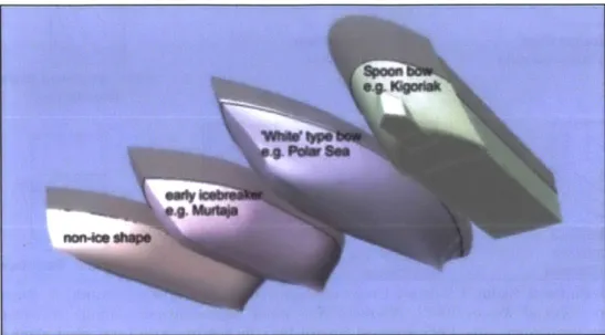
Figure 9 and Figure 10 also gave examples of vessels that existed around the world and exhibited the characteristics of these different hull forms. Polar Sea ("White
Bow" - Operated by the United States), Kigoriak ("Spoon Bow" - Now Operated by
Russia), and Oden ("Flat Family" - Operated by Sweden) were very interesting in that they were all effective at breaking ice but had very different geometry. Figure 11 through Figure 14 provided additional detail to illustrate the differences between "conventional" and "unconventional hull" forms for the Polar Sea and Oden vessels respectively.
Figure 9: Evolution of Ice Breaker Hull Forms Identifying Specifically
the "White bow" and the "Spoon Bow"
Source: C. G. Daley, lecture on ship-ice interaction (Ice Engineering, course taught at Memorial
University of Newfoundland and Labrador, St. John's, NL, 2007), Slide 2.
Figure 10: Evolution
of Ice Breaker the "FlatHull Forms
Family"
Identifying Specifically
Source: C. G. Daley, lecture on ship-ice interaction (Ice Engineering, course taught at Memorial
Polar Sea (Conventional Hull)
Figure 11: Bow Picture of
Polar Sea
Figure 12: Side Picture of Polar Sea
Source: Wikipedia, accessed April 6, 2013, http://en.wikipedia.org/wiki
/USCGCPolarSea_(WAGB-11)
go. 100. USA, Polar Class Icebreaker WABG 1 1 Polar Sea
Source: Lazer One's, Wordpress.com (blog), December 9, 2009,
original drawings completed by www.shipbucket.com, accessed April 6, 2013, http://lazerone.wordpress.com/about/ship-profiles /icebreakers-2/us-wabgll-polar-sea-2/.
Oden (Unconventional Hull)
Figure 13: Bow Picture ofOden
Figure 14: Side Picture of Oden
Source: The Continental Shelf Project (website), accessed April 6, 2013, http://a76.dk/greenlanduk /northuk/gr_n-expeditionsuk
/lomog_2007_uk/
Saween, IOden
ON- A-.-r
Source: Lazer One's, Wordpress.com (blog), December 9, 2009,
original drawings completed by www.shipbucket.com, accessed April 6, 2013, http://lazerone.files.wordpress.com/2009/12/sweden
2.5
Structure of Ice-Capable Ships
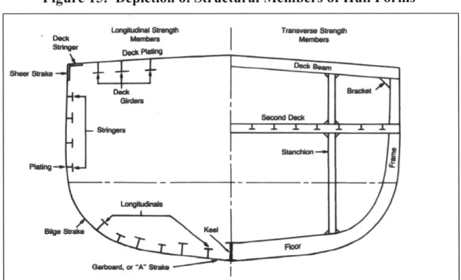
2.5.1 Hull Structure NomenclatureThe structure of a hull form was comprised of a number of structural members that, as a sum, completed the hull form in meeting its intended shape and strength. These structural components were normally arranged in either the transverse framing system or the longitudinal framing system. The transverse framing system was one where the hull plate strengthening ran from one side of the ship to the other side of the ship, i.e. from port to starboard, with connecting members that ran along the length of the vessel. The longitudinal framing system, conversely, was one where the hull plate strengthening ran along the length of the vessel, i.e. from bow to stem, with connecting members that ran from port to starboard. When a design has no dominant type of framing structure then this system was sometimes referred to as a "combination" or "grillage" framing system.4 Figure 15 and Figure 16 identified typical examples of both the transverse and the longitudinal framing systems. Usually long ships would be longitudinally framed on account of the larger bending moments the hull would experience along its length while sailing. Icebreakers, however, were normally framed transversely to withstand the direct local ice loads that occur.
A brief description of the primary structural members mentioned in Figure 15 was
provided for reference:
1. Shell Plating / Strakes - Steel plates that form the hull side and bottom;
2. Frames - Transverse members that support shell plating. Broken into two smaller categories concerning ice-class vessels: Web Frames and Intermediate Frames. Web frames were the larger frame members when different frame sizes existed and the smaller frames were simply referred to as Frames. If there was only one size of frame present in the design, then the distinction of a frame being a web was normally not described;
3. Stringers - Longitudinal members that supported shell plating;
4. Girders - Similar to stringers except these were attached to either deck plating or plating on the bottom of the hull form;
5. Keel - The main girder that ran along the centerline length of the ship;
6. Beams - Transverse members that supported deck plating; and
7. Stiffeners - Transverse or longitudinal members that strengthened the shell plating. Normally referred to as longitudinal structure.5
Figure 15: Depiction of Structural Members of Hull Forms
Luenal S"anMm
De*k PW*Vn
TMsVrse SVWngh
I
hMeand Bruce Johnson, Introduction to Naval Architecture (Annapolis, MD: United States Naval Institute, 1982), fig 5-22.
i Gillmer and Johnson, Introduction to Naval Architecture, 96-106.
Sheer Sake
Figure 16: Depiction of Simple Transversely and Longitudinally Framed Hulls
Transversely Framed Longitudinally Framed
Source: James Roy et al., Longitudinal Vs Transversely Framed Structures For Large Displacement
Motor Yachts, accessed 9 April, 2013, fig 1, http://www.hiswasymposium.com/assets/files/pdf/2009 /Hiswa%20Symposium%202008%20James%2ORoy%2OBen%20Munro.pdf
2.5.2 Icebreaking vs. Ice-strengthened Vessels
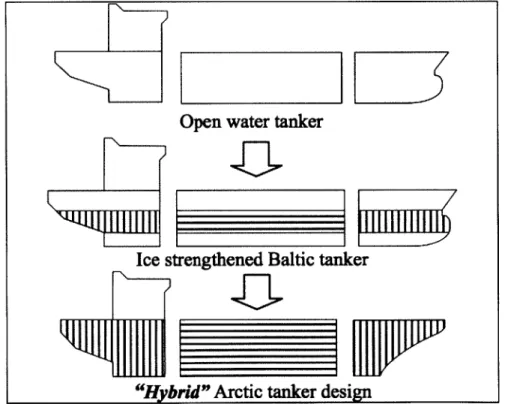
It should be noted that there was a difference between vessels that were categorized as "icebreakers" and vessels that were referred to as being "ice-strengthened". Icebreakers were exactly what their title implies: they were vessels design to break ice. Ice-strengthened ships on the other hand were vessels whose hulls were not necessarily intended to break ice but were instead designed to withstand loads experienced due to the impact of ice on the hull. Typical ice-strengthened ships were vessels that sailed through a channel cut into the ice by an icebreaker, i.e. ice-strengthened ships were designed to be escorted, and led, by an icebreaker. The Baltic Sea was a geographical region where this was witnessed regularly. Finland and Sweden operated a fleet of icebreakers that maintained cleared channels through the ice to allow ice-strengthened merchant ships to sail through.
The structure normally associated with ice-strengthened vessels was comprised of a strengthened bow region as well as an ice belt region. The stem of the vessel may have been strengthened as well depending on specific operational requirements. Figure 17
identified three different types of vessels and where the location of higher strength hull structure would be compared to open-water vessels that did not come into contact with ice. In the figure the vertical lines indicated the framing structure was transversely oriented and horizontal lines indicated the framing structure was longitudinally oriented. Here both the "ice-strengthened Baltic tanker" and "Arctic tanker design" were using combination framing. The "Ice strengthened Baltic tanker" depicted the concept of an "ice belt" that is referred to in ice-strengthened vessels.
Figure 17: Depiction of Strengthened Structure for "Ice-strengthened" Vessels
"Hybrid" Arctic tanker design
Source: Robert Tustin, Mikko Niini, and Erkki Ranki, "Arctic tankers: current and future
structural design practice", IceTech Symposium 2010, (September 2010): fig 9.
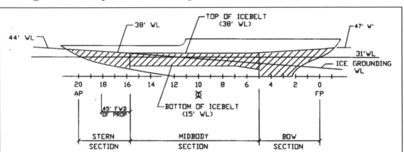
Icebreakers were similar to ice-strengthened vessels as they too had an ice belt and strengthened bow structure. However, the strengthened bow structure would extend all the way to the bottom and extend a certain distance aft. The ice belt structure would
also be extended lower and the stem would be strengthened for astern operation when maneuvering in ice. A typical schematic of strengthened structure for icebreakers can be found in Figure 18. One other big different between ice-strengthened vessels and icebreakers that was not apparent in Figure 17 and Figure 18 was that icebreaker bows would have significantly different bow geometry compared to "normal" open-water vessels as discussed in Section 2.4.
Figure 18: Depiction of Strengthened Structure for Icebreakers TOP OF ICEBELT 44' WIL38' L (38' L) 47, W, . . .. . .31'VL ICE GROUNDING VL 20 18 16 14 12 10 8 6 4 2 0 AP FP BOTTOM OF ICEBELT (15' WL)
STERN MIDBODY BOV
SECTION SECTION SECTION
Source: John C. Daidola, and Rubin Sheinberg, "A Procedure for the Structural Design of Icebreakers and Other Ships Navigating in Ice", SNAME Transactions, Vol 96, (1988): 271-307.
2.6 Development of Polar Code
2.6.1 Classification Societies
A classification society is defined as an organization that would provide
"statutory services and assistance to the maritime industry and regulatory bodies as regards maritime safety and pollution prevention, based on the accumulation of maritime knowledge and technology."6 As such, vessels were normally designed to a specific classification society where the vessel would receive specific notations that identified the standards to which it was designed and constructed. These standards were normally referred to as "rules" or "codes" for ship design and were in addition to any internationally recognized design criteria set forth under conventions, i.e. International
Convention on the Safety of Life at Sea (SOLAS) and International Convention for the
Prevention of Pollution
from
Ships (MARPOL).Although over 50 classification societies existed, those that received references most commonly are listed below, in no particular order:7
1. American Bureau of Shipping (ABS) 2. Lloyd's Register (LR)
3. Det Norske Veritas (DNV) 4. Bureau Veritas (BV)
5. Germanischer Lloyd (GL)
2.6.2 IACS and the Polar Code
Most shipping were classified by one of 10 main classification societies, and over the past half century many collaborative efforts have occurred between these different organizations.8 As such, the International Association of Classification Societies Ltd.
(IACS) was formed in 1968 and was governed by members from each of the participating
classification societies who made up its membership.9 Its purpose of IACS was to bring a unified voice to all participating classification societies and share technical knowledge between them. Under this authority, "Unified Requirements" have been developed by
IACS and thus have been adopted by its member societies. In 2007, one of these
"Unified Requirements" was the Unified Requirements Jbr Polar Ships (hereinafter referred to as IACS UR), which was ratified by all participating classification societies under IACS. The IACS UR stipulated the minimum requirements for any vessel that intended to sail in the defined polar locations of the Artic and Antarctica.
7 Ashe, "Classification and Certification".
8 Ashe, "Classification and Certification".
Prior to IACS UR, each classification society maintained its own method to describe how icebreakers and ice-strengthened ships were to be designed and constructed.
If a ship was intended to operate in the territorial waters of one of the northern nations,
then those counties normally held their own requirements as well. An example of this in North America was the Canadian Arctic Shipping Pollution Prevention Regulations (ASPPR), which states requirements for vessels to operate in Canadian waters in addition to requirements by classification societies.'0 All northern nations hold similar territorial water requirements similar to Canada. Given this abundance of regulation between the different classification societies and northern nations that governed how ice-capable ships should be built, and each of these regulations being based on different underlying principles of design, the IACS UR was produced as a method to resolve and unify the structural requirements under one minimum standard.
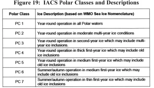
In addition to unification of requirements, the IACS UR also brought with it the novel concept that steel hull structures could be designed with plastic deformation capacity in mind, as opposed to designing vessels to never surpass the elastic-plastic limit, or yield point. This concept was first introduced by the ASPPR in the mid 1990's on account of it being commonly understood that when a vessel was transiting an ice pack, the ice field was not completely uniform with the same type of ice as described in Section 2.3." For example, it was likely that a region of first year ice may contain some old ice (second year ice or multiyear ice) that was hidden within the flow and would stronger than first year ice. As well, hummocks and ice ridges may have been present that also differ significantly in strength compared to the surrounding ice type. Therefore ships should have been designed to account for these variations ice type encounters. It was defined under ASPPR and IACS UR that the hull structure would be primary designed for the elastic limit when concerning the typical type of ice the vessel would be transiting in, but also have the structure's plastic capability to protect the vessel from encounters with stronger ice that would overstress the hull beyond yield upon impact. Hence, there were 7 Polar Classes defined within the IACS UR that stipulate the typical
10 Department of Justice, "Artic Waters Pollution Prevention Regulations."
type of ice the vessel would be intended to operate in but also make aware of the other types of ice that may be present.'2 These classes and descriptions are found in Figure 19.
Figure 19: IACS Polar Classes and Descriptions
Source: IACS (website), "Unified Requirements for Polar Ships", accessed April 15, 2013,
http://www.iacs.org.uk/document/public/Publications/Unified-requirements/PDF/URlpdf41O.pdf
The IACS UR broke a hull form into different regions and specified what strengthening was required for each region for each Polar Class. The hull was divided vertically into three sections labeled the "Ice Belt", "Lower", and "Bottom", and divided horizontally into four sections labeled the "Stem", "Midbody", "Bow Intermediate", and "Bow". As the "Bow Region" was not divided vertically, these horizontal and vertical divisions generated a set of 10 regions as seen in Figure 20. Before the IACS UR, icebreakers had three strengthened hull sections as described in Section 2.5.2, namely the bow, ice belt, and stem. Some rules went so far as to require an additional area adjacent to and below the ice belt, as was found in the ASPPR.'3 With the adoption of IACS UR, all Polar Class vessels would have to comply with the prescriptive criteria for each of the
10 newly defined regions.
12 IACS, "Unified Requirements for Polar Ships."
13 Department of Justice, "Artic Waters Pollution Prevention Regulations."
Polar Class Ice Description (based on WMO Sea Ice Nomenclature) PC I Year-round operation in all Polar waters
PC 2 Year-round operation in moderate multi-year ice conditions PC 3 Year-round operation in second-year ice which may include
multi-year ice inclusions.
PC 4 Year-round operation i thick first-year ice which may include old ice inclusions
PC 5 Year-round operation in medium first-year ice which may include
old ice inclusions
PC 6 Summer/autumn operation in medium first-year ice which may
include old ice inclusions
PC 7 Surur/mautum operation in thin first-year ice which may incude
Figure 20: Defined Regions for Strengthening of Polar Class Hull Forms
ForPCI,2.3&4 xl.15m; ForPC5,6.7 xa1.0m:
wih "xmeas at of bow region
SAnglit-10 degre atu 0.04L aft of Ag =0 degres atUnLA
hdbteedfii U! I um P20 M LIW LJLS, Bli 0. 7b-4. 1 5L WL Angle a0 degrees AP RL Angle 10 deres
T ahanes in the AP max fo snmu
half bIaNdi a U*Lm
UlW
M5 UWL
mo LoMb R i
Source: IACS (website), "Unified Requirements for Polar Ships", accessed April 15, 2013,
http://www.iacs.org.uk/document/public/Publications/Unified-requirements/PDF/URI_pdf410.pdf
The abbreviations found in the figure stand for:
7. B - Bow Region,
2. Bli - Bow Intermediate Ice Belt Region,
3. BEl - Bow Intermediate Lower Region, 4. Bib - Bow Intermediate Bottom Region,
5. Mi - Midbody Ice Belt Region,
6. M1 - Midbody Lower Region,
7. Mb - Midbody Bottom Region, 8. Si - Stern Ice Belt Region,
9. Sl - Stem Lower Region, 10. Sb - Stem Bottom Region,
11. UIWL - Upper Ice Waterline, and 12. LIWL - Lower Ice Waterline.
The UIWL and LIWL were the defining lines upon which the Ice Belt Region was described by the rules. These lines or "waterlines" referred to the extreme drafts at which the vessel would operate. Thus the Ice Belt boundaries were offset above and below the
UIWL and LIWL respectfully, which can also be seen in Figure 20. Other specific
defining points for the boundaries were based on geometry of the hull form, e.g., the transition from "Bow" to "Bow Intermediate" was when the waterline angle was 10 degrees along the UIWL. 4
2.6.3 IACS, ABS, and the Polar Code
When the IACS UR was adopted, all participating classification societies of IACS had to figure out where their previous ice classification system would fit. In terms of the classification society ABS for example, they originally had a classification system ranging from A5 thru Al in descending order of capability for multiyear ice (A5 being the most capable icebreaker) and AO, BO, CO, and DO for first year ice.5 They also
maintained the "Baltic" notations for vessels operating in the Baltic Sea. In comparison to the IACS UR's "Polar Classes", the A5 through Al notations were found to be more conservative in certain areas and less conservative in others. Thus ABS developed two additional notations to be used in addition to a "Polar Class" notation. These were the "Enhanced" and "Icebreaker" notations that go above and beyond the IACS UR Polar Classes. The resulting notation scheme can be seen in Figure 21. ABS now maintains four separate categories for vessels that operate in ice, the first was for vessels looking for just the "Polar Class" notation, one for "Polar Class, Enhanced" notation, one for "First Year Ice Class" notation, and one for a "Baltic Class "notation. Under the title of each of these categories are the ABS section reference numbers where the specifications would
1 IACS, "Unified Requirements for Polar Ships."
be found for each notation. Only the shaded "Polar Class, Enhanced" notations were eligible for the addition notation of "Icebreaker".'6
Figure 21: ABS Notations for Vessels that Operate in Ice
Polar Class Polar Class, Enhanced First-year Ice Class Baltic Class
(6-1-1, 6-1-2, 6-1-3) ^-1 (6-1-5) (6-1-6) PC2 PC3 PC5 PC6 1AA PC7 PC7, Enhanced AO 1A BO 1B Co 1C
DO
Note: The ice classes are eligible for Ice Breaker class notation.
Source: American Bureau of Shipping (website), Steel Vessel Rules 2013, accessed April 6, 2013.
http://www.eagle.org/eagleExternalPortalWEB/ShowProperty/BEA%20Repository/Rules&Guides/C urrent/2_SVR2013/part6.
An interesting thing to note was the horizontal equivalent ranking that was implied by Figure 21 such that "Baltic Class IAA" was similar to "PC6" or "PC6, Enhanced". The reason for this was not precisely known. The author believed that this horizontal ranking was not intended to imply equivalence but merely identify and lower
subordinate in the horizontal hierarchy, e.g., "PC6" would meet "Baltic Class 1AA"
requirements but not vice versa. That said, any "Enhanced" or "Icebreaker" notation would supersede that of a "Polar Class" notation.
ABS Steel Vessel Rules 2013 (ABS SVR), Part 6, Chapter 1, Section 2 solely dealt with the Polar Class notation requirements and was essentially the IACS UR translated into ABS terminology. For example, Figure 20 was taken from the IACS UR, but an identical figure appears in the ABS SVR. These rules only spoke to the hull regions defined from the upper boundaries of the "Ice Belt" and "Bow" Regions extending downward. The upper hull above this region would be classified under a
different section of ABS SVR, as it was not expected to ever come into contact with ice. It was therefore normal to see an icebreaker hull form structure that was very dense in the regions defined by Figure 20, which opens up when above those defined ice-strengthened regions, an example of which is depicted in Figure 22.
Figure 22: Typical Icebreaker Hull Form Structure
Unstrengthen Hull Structure Above Ice Belt and Bow Regions
Ice Belt Region Structural Members Bow Region Structural Members Bottom Region Structural Members
Other classification societies developed similar notation systems to those of ABS, the specifics of which were deemed unnecessary for the purposes of this paper.
2.7
Current Method of Design
When designing an icebreaker or an ice-strengthened vessel, the designer must first understand the relative importance of different areas of performance, specifically icebreaking, ice-transiting, and open-water sailing. The hull form was one of the essential things to be considered first, given, for example, the strong link between a
ship's bow and how efficient the hull from would be at clearing ice. Hull form geometry and powering were fundamentally linked, so iterative steps are taken to determine what was the best combination of hull form geometry and propulsion to achieve desired results for icebreaking, ice-transiting, and open-water sailing, as defined by the operational requirements of the vessel being designed. For example, an icebreaker's focus would be on its ability to break thick multiyear ice using efficient propulsion that is environmentally friendly. On the other hand, an ice-strengthened container vessel that operates in the Baltic Sea would be more focused on open-water efficiency, strengthening the hull just enough to safely transit behind an icebreaker clearing its path.
Hull structure was only considered in the design process after a hull form's geometry and installed propulsion was completed. This methodology was confirmed by one of the world's leading design firms of ice-technology: Aker Arctic, 17 and is
illustrated in Figure 23, which identified the iterative loop with hull form geometry and propulsion design.
Figure 23: Typical Design Process for Ice Class Vessels
Polar Class e "cb 'k '' I'-c'ub"
* Escort and Ice Management Duties
*Open Water Resistance
Hull Form *ce Bakming Resistance
ePowerina rements
Pro n Eirmental Concerns
Propulsion Deelownent
Hull e&e aStde rmee
Strutur Plate, Girder, Stringer, & Framte Scantlings
Structure e Frame No. of Girders / Strners
eLocal structure can now be determined along with
Detail Design other detals of vessel design
As seen in the figure, designing the hull structure followed the decisions on the hull form and propulsion. During this phase, one of two methods were commonly employed. The first method was to design a structure that was implemented before on vessels of similar design, and was fairly well understood through parametric analyses., Alternatively, the designer could conduct an optimization routine to minimize weight but
still comply with necessary standards for the specific ice-class/notation.19 The structural design was then ready to proceed into the "Detailed Design" phase where local structure and outfitting of the vessel were generated, thus finishing the design development process for hull form and hull structure.
2.8 Motivation of Thesis
2.8.1 Development of Research Concept
When designing an ice-class vessel's structure, the focus of the naval architect was often more drawn towards minimizing weight than to look at the aspects of production during hull construction. That is not to say that aspects of production were completely ignored, but rather that minimizing weight, with its impact on the displacement of the vessel, was often viewed as more critical. As history has shown, this focus on weight minimization can lead to small frame spacing and high grade material that make the fabrication of an ice-class hull more difficult to achieve.2 0 This led to the
question of what was the cost trade-off, here specifically for an ice class vessel, between minimizing materials and designing a more easily produced ship?
To answer this question in terms of cost, one needed to know how the cost of hull structure was calculated. This included knowing the material and production metrics that influenced the cost. However, obtaining this information proved difficult when it came to ice-capable vessels, as was displayed by the reputable and robust shipyard National
Steel and Shipbuilding Company (NASSCO), considered to be one of the best shipyards
18 Discussion with production engineering at Irving Shipbuilding Inc., 18 October 2012. 19 Kari Laukia, telephone interview, October 30, 2012.
in North America. NASSCO had a detailed understanding of its production metrics for many vessels, yet even they were in the process of conducting a National Shipbuilding Research Program (NSRP) to determine how to more efficiently design/construct an ice-class vessel.2 One issue lied in the amount of available data to develop specific ice-ice-class metrics: the number of ice-capable ships produced worldwide was extremely small in comparison to the greater shipbuilding industry. Unfortunately, production metrics of open-water vessel construction did not necessarily translate to ice-class vessel construction, for reasons including the differences detailed in Section 1 and elsewhere in this paper, and some metrics that may have translated proved not to be scalable to ice-class applications. Thus, determining the trade-off between minimizing materials and designing a ship that is easier to produce at the shipyard began with investigation of the various production metrics that would go into ice-capable vessel construction. This required, in turn, knowledge of how vessels were priced.
2.8.2 Current Cost Estimation Techniques
There were two work breakdown structures when it comes to defining the necessary work to be done when constructing a vessel. There was the Systems-Oriented Work Breakdown Structure (SWBS) and the Product-Oriented Work Breakdown
Structure (PWBS). Examples of each can be found in Figure 24 and Figure 25.
Figure 24: Example of SWBS Format
SWBS Group Title
000 General Guidance and Administration
100 Hull Structure 200 Propulsion Plant
300 Electric Plant
400 Command and Surveillance
500 Auxiliary Systems
600 Outfit and Furnishings
700 Armament
800 Integration/Engineering
900 Ship Assembly and Support Services
Source: Richard Lee Storch, et al., Ship Production (Jersey City, NJ: The Society of Naval Architects
and Marine Engineers, 2007), 54.
Figure 25: Example of PWBS Format
Hull Block Zone Outfitting Lone Famning
Construction Method Method Method
(H BCM) (ZOFM) (ZPTM)
Source: Richard Lee Storch, et al., Ship Production (Jersey City, NJ: The Society of Naval Architects
and Marine Engineers, 2007), 56.
Once a work breakdown structure was created then a cost estimating tool could be used. The two main types of cost estimating in shipbuilding were weight-based and production-based. Normally weight-based cost models were associated with the SWBS and production-based cost models are associated with the PWBS, however weight-based could also be applied to PWBS. In North America it appears, from the author's personal investigations and work experience, that a majority of the shipyards conduct
weight-based cost estimating. Only NASSCO was found to fully employ PWBS and a production-based costing tool. This made collection of information concerning production factors difficult to achieve for this paper due to their lack of availability.
For reference, typical weight-based costing systems would price the hull structure
by a means of:
Total Cost = Total Tonnage * Material Rate + Total Tonnage * Production Rate
Where
Material Rate = Material Cost per Tonne And,
Production Rate = Production Cost per Tonne Or,
Production Rate = Production Time per Tonne * Wages
Sometimes these "rates" would be increased in areas where difficulty was expected when constructing the vessel, e.g., the production rate (cost per tonne) for bow structure would likely be higher than compared to the side section in the midbody due to the complex curvature encountered in the bow. This complex was more time consuming and thus more costly to work with.
These rates were sometimes also increased by applying a "difficulty rate factors" when conducting the cost estimating. The result of these "rates" being multiplied by their respective "rate factors" produce what was defined as the Cost Estimating Relationships (CERs). In essence, a CER was a "base rate" that has been increased by a "difficulty rate factors" for a specific weight or process.
Referring back to Figure 24, it can be seen that there were many CERs needed to estimate a design's cost, as there would be different CERs associated with each SWBS group, as well as with the many additional levels of breakdown. As shipyards have historically only maintained weight-based CERs and have not tracked production-based CERs, there was little readily available information regarding production CERs to use. Since this paper only dealt with construction of hull forms, most shipyards were at least willing to speculate on what production factors would be of the most import when it
comes to hull construction for icebreakers and ice-strengthened vessels, even if they did not have historical data to provide.2 3 The recurring ideas suggested as drivers of
production cost were:
1. Material Cost - influenced by:
a. Material grade,
b. Amount being purchased, and
c. Material thickness / weight.
2. Labor Cost - influenced by:
a. Thickness of material being joined,
b. Number of weld passes required,
c. Material grade, and
d. Accessibility.
3. Overhead Cost - unique to each shipyard.
In addition, SPAR Associates Inc., a company that tracked a variety of metrics of North American shipyards, provided an overview that confirmed the suggestions by the various shipyards. Thus, all of these suggestions were used when conducting the trade-off analysis. In addition to these factors, an extra "region difficulty factor" was suggested
23 Shipyards include: Irving Shipbuilding Inc., Seaway Marine & Industrial Inc., NASSCO, Seaspan Vancouver Shipyards, J.M. Martinac Shipbuilding Corp.
to help account for plate curvature that is seen at the bow or stern of vessel construction if it was not already captured in a separate CER.2
Besides material and labor CERs, overhead was a concern of costing. Depending on the company, different methods would be witnessed for the allocation of overhead costs. Some companies allocated overhead cost within the different CERs, while others simply listed overhead as a separate cost in their estimating formula. From the author's personal experience it was noticed that when shipyards were working with government contracts, overhead would be separated and identified openly where as private contracts would see overhead built into material and labor costs.
3.0
Program Development
3.1 Goal of Program
The purpose of the research conducted was to investigate the specifics of the trade-off between a Polar Class vessel designed by minimizing materials and one designed to be easier to produce at the shipyard. Without performance and cost data from large sets of vessels built using both methods, it was decided to build a program that could generate representative sets of data for comparison to analyze this problem. Given a hull form, the program needed to generate structural arrangements that met a given classification society's rules. The program then needed to select the arrangements that either minimized weight or minimized production cost within a set of user-defined material and labor metrics. By varying inputs to the program, sets of hull structures could then be generated for trade-off analysis. The trade-off analysis was conducted by comparing cost savings versus the increase in weight when production costs optimization was done compared to weight optimization.
The numerical tool's purpose was to optimize a hull form's structure to reduce labor costs during construction while adhering to the newly defined IACS UR. The numerical tool required a user input the hull's external geometry constraints based on the vessel's lines plan, which have already been optimized for hydrodynamics, then it would output an optimized structural hull form based on the newly adopted polar rules and user specified production metrics.
In order to build the program, various labor and material metrics, as well as constraints had to be determined. The information described under Section 2.8.2 was decided as the type of labor metrics to be used. Material metrics were already known but still required user specified values. Finally, the constraints would be stipulated by the classification society chosen for the design of the vessel. For the reader's clarification, production metrics refer to both material and labor metrics. Overhead will not be included for the purposes of this paper.
3.2 Initial Program Setup
MATLAB, a product of Mathworks*9, was used to develop the program due to the user-friendly environment in developing optimization routines and the diverse set of optimization algorithms available in MATLAB's Optimization Toolbox. Additionally, a MATLAB code was provided that could perform weight minimization for a given type of hull form,2 5 which provided a starting point.
As the investigation was interested in evaluating the trade-off between weight and cost for two methods of designing ship structure, the objective function was the total cost of production. The total production cost was found by the summation of the cost of material and the cost of labor, i.e. one sub-function for the calculation of material weight, and the other for the calculation of labor cost. The weight of material was converted to a cost using its specific material price per unit weight. This equation was defined as shown below:
Total Cost = Material Weight * Cost per Unit Weight + Cost ofLabor
Where,
Material Weight was a sub-objective function
And,
Cost ofLabor was a sub-objective function
In doing this, the objective sub-function Cost ofLabor was able to be de-activated such that the optimization routine would only produce a solution that would give the minimum cost for material, effectively creating an optimization routine for the minimization of structural weight. The main objective function can be found in Appendix B, Section 2, with the weight objective sub-function in Appendix B, Section 3 and the labor cost objective sub-function found in Appendix B, Section 4.
The constraints of the optimization problem were set by the classification society's rules concerning Polar Class vessels. These were prescriptive requirements that were directly translated into the constraint file for the optimization routine. This code file can be reviewed at Appendix B, Section 5.
The design variables of the program were the scantlings (dimensions) and the number of the structural members to be used in the hull form that covered:
1. Frame Scantlings,
2. Stringer Scantlings (Girders and Stringers are only referred to as stringers in the code),
3. Shell Plating Thicknesses, and
4. Number of Stringers.
These design variables were subsequently passed between the main objective function, sub-objective functions, and constraints to achieve the parameters that produce the desired solution.
Setup of the optimization algorithm, along with user inputs and displayed outputs of the program are found under the "Main Program" file. The specifics of these inputs and outputs will be explained in more detail in Section 4.1.1. The Main Program code can be found in Appendix B, Section 1.