HAL Id: hal-00614166
https://hal.archives-ouvertes.fr/hal-00614166
Submitted on 9 Aug 2011
HAL is a multi-disciplinary open access
archive for the deposit and dissemination of
sci-entific research documents, whether they are
pub-lished or not. The documents may come from
teaching and research institutions in France or
abroad, or from public or private research centers.
L’archive ouverte pluridisciplinaire HAL, est
destinée au dépôt et à la diffusion de documents
scientifiques de niveau recherche, publiés ou non,
émanant des établissements d’enseignement et de
recherche français ou étrangers, des laboratoires
publics ou privés.
Strategy for Visually-guided Micro-Air Vehicles
Lubin Kerhuel, Stéphane Viollet, Nicolas Franceschini
To cite this version:
Lubin Kerhuel, Stéphane Viollet, Nicolas Franceschini. Steering by Gazing: An Efficient Biomimetic
Control Strategy for Visually-guided Micro-Air Vehicles. IEEE Transactions on Robotics, IEEE, 2010,
26 (2), pp.307-319. �10.1109/TRO.2010.2042537�. �hal-00614166�
Steering by Gazing: An Efficient Biomimetic
Control Strategy for Visually-guided Micro-Air
Vehicles
Lubin Kerhuel, Stéphane Viollet, Member, IEEE, and Nicolas Franceschini
Abstract—OSCAR II is a twin-engine aerial demonstrator equipped with a monocular visual system, which manages to keep its gaze and its heading steadily fixed on a target (a dark edge or a bar) in spite of the severe random perturbations applied to its body via a ducted fan. The tethered robot stabilizes its gaze on the basis of two Oculomotor Reflexes (ORs) inspired by studies on animals:
• a Visual Fixation Reflex (VFR) • a Vestibulo-ocular Reflex (VOR)
One of the key features of this robot is the fact that the eye is decoupled mechanically from the body about the vertical (yaw) axis. To meet the conflicting requirements of high accuracy and fast ocular responses, a miniature (2.4-gram) Voice Coil Motor (VCM) was used, which enables the eye to make a change of orientation within an unusually short rise time (19ms). The robot, which was equipped with a high bandwidth (7Hz) “Vestibulo-ocular Reflex (VOR)” based on an inertial micro-rate gyro, is capable of accurate visual fixation as long as there is light. The robot is also able to pursue a moving target in the presence of erratic gusts of wind. Here we present the two interdependent control schemes driving the eye in the robot and the robot in space without any knowledge of the robot’s angular position. This “steering by gazing” control strategy implemented on this lightweight (100-gram) miniature aerial robot demonstrates the effectiveness of this biomimetic visual/inertial heading control strategy.
Index Terms—gaze stabilization; smooth pursuit; Oculomotor Reflexes (ORs); Visual Fixation Reflex (VFR); Vestibulo-ocular Reflex (VOR); Micro-Air Vehicle (MAV); steering strategy; sen-sorimotor control; biorobotics; autonomous robots;
I. INTRODUCTION
T
OMORROW’S Micro-Air Vehicles (MAVs) will be ca-pable of similar performance to those of flying animals (insects and birds): they will be able to navigate safely in unknown environments, and vision has turned out to be the most suitable sensory mode on which to base their guidance. In comparison with MAVs, systems such as those based on GPS signals have several weaknesses, including their poor resolution, their low signal-to-noise ratio in canyons and building interiors and their failure to cope with unexpectedly encountered stationary or moving targets. On the other hand, active sensors such as RADARs and FLIRs are so power-consuming that they are not at all suitable for use on MAVs.L. Kerhuel, S. Viollet and N. Franceschini are with the Biorobotics Lab. at the Institute of Movement Sciences, CNRS/Univ of the Mediter-ranean, 163, avenue de Luminy (CP 938), 13288 Marseille, Cedex 09, France (email: [email protected], [email protected], [email protected])
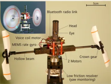
Fig. 1. OSCAR II is a tethered aerial robot which controls its heading about the vertical (yaw) axis by driving its two propellers differentially, based on what it sees. The eye of OSCAR II is mechanically decoupled from the head (which is mounted firmly on the “body”). The visual system enables the robot to fixate a target (a vertical edge placed 1 meter ahead). Two Oculomotor Reflexes (ORs), the Vestibulo-ocular Reflex (VOR) and the Visual Fixation Reflex (VFR), stabilize the robot’s line of sight (its gaze) in response to any severe disturbances (such as gusts of wind) liable to affect its body. The heading control system in which the ORs are involved (see Fig. 7) aligns the robot’s heading with the gaze, and is thus constantly catching up with the gaze. Robot OSCAR II is mounted on a low-friction, low-inertia resolver, which monitors the heading with a high level of accuracy. (Top left photo by Franois Vrignaud)
Most of the few visually guided MAVs developed so far trans-mit images to a ground station via a radio link and extensive image processing is performed off-board. The whole process may suffer from undesirable time lag and untoward “drop-outs”. Three noteworthy exceptions are the MC2 microflyer [1], a small aircraft wing [2] and a quadrotor [3] which use Optic Flow to react autonomously.
Flying insects and birds are able to navigate swiftly in un-known environments with very few computational resources. They are not guided via radio links with any ground stations and perform all the required calculations on-board. The ability to stabilize the gaze is the key to an efficient visual guidance system, as it reduces the computational burden associated with visuo-motor processing. Smooth pursuit by the eye is another requisite: the ability to fix the gaze on a given moving feature significantly reduces the neural resources required to extract relevant visual information from the environment. Although
their brains are so small and their eyes have so few pixels, flying insects can perform some extraordinary behavioral feats, such as navigating in 3-D environments, avoiding stationary and moving obstacles, hovering [4], [5], tracking mates [6] and intruders [7], and intercepting prey [8], relying solely on visual guidance. Recent studies have shown that freely flying flies keep their gaze fixed in space during 100 − 200ms episodes, using very fast stabilization reflexes [9]. The freely flying sandwasp, for instance, keeps its gaze amazingly stable despite the large thorax rolls it performs [10]. The stringent requirements involved in visual stabilization may explain why eye movements are among the fastest and most accurate of all the movements in the repertory of the animal kingdom.
Gaze stabilization is a difficult task because the eye control system must compensate both quickly and accurately for any sudden, untoward disturbances caused by the vagaries of the supporting head or body. In the freely flying housefly, active gaze stabilization mechanisms prevent the incoming visual information from being affected by disturbances such as vibrations or body jerks [9], [11]–[13]. This finely adapted mechanism is way beyond what can be achieved in the field of present-day robotics.
The authors of several studies have addressed the problem of incorporating an active gaze stabilization system into mobile robots. After the pioneering studies on the “Rochester head” [14], the “Oxford head” [15] and the “Harvard head” [16], a number of gaze control systems were developed, in which retinal position measurements were combined with inertial measurements [17], and the performance of these systems were assessed qualitatively while slow perturbations were being applied by hand. Shibata and Schaal [18] designed and built a gaze control device based on an inverse model of the mammalian oculomotor system. This device equipped with a learning network was able to decrease the retinal slip 4-fold in response to moderate frequency perturbations (of up to 0.8Hz). Another adaptive image stabilizer designed to improve the performance of a robotic agent was built and its ability to cope with moderate-frequency perturbations (of up to 0.6Hz) was tested [19]. An adaptive gaze stabilization controller was recently presented and its performance were measured in the 0.5-2Hz frequency range [20]. Other gaze stabilization systems inspired by the human Vestibulo-ocular Reflex (VOR) have also been designed for mobile robots [21]–[23], but the performance of these systems have not yet been assessed quantitatively. Miyauchi et al [24] have shown the benefits of mounting a compact mechanical image stabilizer onboard a mobile robot travelling over rough terrain. Twombly [25] has performed computer based simulations on a neuro-vestibular control system designed to endow a walking robot with active image stabilization abilities. Wagner et al. [26] built a fast responding oculomotor system using air bearings and bulky galvanometers [26]. Maini et al. [27] recently succeeded in implementing fast gaze shifts in an anthropomorphic head without using any inertial sensors. In the field of humanoid robotic research, two recent studies have described the enhanced performance of a biped robot endowed with gaze control mechanisms [28], [29]. None of the technological solutions ever proposed are compatible,
however, with the drastic constraints imposed on autonomous Micro-Air Vehicles (MAVs) in terms of their mass and size.
Fast flying insects such as flies possess a fine set of oculomotor reflexes that are the key to their outstanding heading stabilization performance. These reflexes are of partic-ular relevance to designing tomorrow’s miniature autonomous terrestrial, aerial, underwater and space vehicles. As we will see, a visually mediated heading stabilization system requires:
• a mechanical decoupling between the eye and the body
(via the eye’s orbit and the neck, as in birds, or via the neck alone, as in insects).
• a fast and accurate actuator. Blowflies, for instance,
control their gaze using no less than 23 pairs of micro-muscles [30].
• a Visual Fixation Reflex (VFR) that keeps the gaze locked onto a contrasting target.
• a Vestibulo-ocular Reflex (VOR), which is an active in-ertial reflex that rotates the eye in counter phase with the head. Flies typically use inertial reflexes of this kind, based on the gyroscopic haltere organs located on the thorax, especially when performing yaw [11] and roll movements [12]. A similar inertial reflex was developed several hundred million years later in mammals including humans. Rhesus monkeys’ VOR operates in the 0.5−5Hz [31] and even 5 − 25Hz [32] frequency range, and is therefore capable of even faster responses than the human visual system.
• a proprioceptive sensor measuring the angular position of the eye relative to the head and that of the head relative to the body. The question as to whether an extrareti-nal proprioceptive sensor exists in primates’ oculomotor system is still a matter of controversy [33], [34], but a sensor of this kind does exist in flies, in the form of the prosternal organ. The latter organ consists of a pair of mechanosensitive hair fields located in the neck region [35], [36], which measure any head vs body angular deviations on the pitch [9], roll [12] and yaw axes [37].
• an active coupling between the robot’s heading and its
gaze, via the oculo-motor reflexes: the visual fixation reflex (VFR) and the vestibulo-ocular reflex (VOR).
Although the present study was inspired by insects’ and vertebrates’ oculomotor systems, our quest was primarily for the performance, and no attempt was made to faithfully model any of the oculomotor control systems described in insects and vertebrates during the past 50 years. In the sectionII, the twin-engine aerial platform is described. In the sectionIII, our one axis “steering by gazing” control strategy is explained. In the section IV, we describe how this strategy was implemented on a miniature aerial robot, called OSCAR II, which acquired the ability to fixate a stationary target and to pursue a moving target despite the severe aerodynamic disturbances that was deliberately imposed on its body. OSCAR II is the first aerial robot capable of these performance, thanks to the fact that its eye is decoupled from its body. Some of the robot performance is illustrated in the supplement video.
II. THEOSCAR IIAERIAL ROBOT
A. The robotic platform
Like its predecessor OSCAR I [38], OSCAR II (see figure
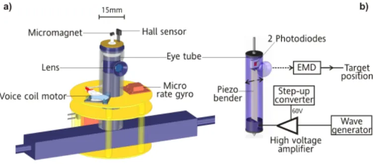
1) is a twin-engine aerial platform equipped with a self-stabilizing visual/inertial system which operates about the vertical (yaw) axis. In addition, OSCAR II features an oculo-motor mechanism that gives its eye the ability to orient relatively to its body within a range of ±35◦. This additional degree of freedom mimicks the mechanical decoupling be-tween eye and body that is so characteristic of animals, from box jellyfish to humans. The sighted robot is able to adjust its heading accurately about the body yaw axis by driving its two propellers differentially via a miniature custom made 1-g dual sensorless speed controller (for a detailed description, see [39]). The robot’s “body” consists of a carbon housing containing the two motors driving the robot’s propellers’ (see fig.1 and fig.2). These DC motors are mounted close to the yaw rotational axis to minimize the inertial load. Each motor transmits its power to its respective propeller (diameter 13cm) via a 8 cm long carbon fiber shaft, rotating on micro-ball bearing within the hollow beam, ending in a crown gear (with a reduction ratio of 1/5). The OSCAR II robot weighs 65g without the batteries. This weight includes the two engines with their drive mechanisms and their dedicated sensorless controller [39], the propellers, the eye with its VCM based position servo-system, the micro rate gyro (Analog Device ADIS 16100), the piezo bender, the complete electronics based on Surface Mounted Device (SMD) technology and the blue-tooth circuit for remote data monitoring. Two separate Li-Polymer battery packs are used to power the robot: a low-power pack (3.6V-100mAh, 3g) for the electronics and a high-power pack (7.2V-620mAh, 34g) for the two propeller motors. The robot’s “head” is a large (diameter 15mm) carbon tube mounted firmly onto the motor casing. Within the head, an inner carbon “eye tube” can turn freely about the yaw axis. This eye tube is spring-loaded between a pivot bearing (at the bottom) and a bored micro-conical ball bearing (at the top), through which a 1-mm steel axle passes freely. Thanks to a micromagnet glued to the tip of this axle, a tiny contactless Hall sensor (see Fig.2) accurately gauges the eye-in-robot orientation θer (see Fig.3). The complete visual
system including the complete OSCAR sensor (see [40]), its VCM, its driver and the digital controller weighs only 22.5g. The eye can rotate within the ±35◦ range. We implemented a detection system that prevents the VCM from saturating and thus from being damaged by over current. After a short delay, this system automatically resets the VCM’s angular position whenever the set-point of the eye’s orientation is too large.
B. The robot’s visual system
The robot’s eye consists of a miniature lens (diameter 5mm, focal length 8.5mm), behind which an elementary “retina” composed of a single pair of matched PIN photodiodes performs a horizontal scanning operation at a frequency of 10Hz: this retina is driven by a fast piezo bender (Physik Instrumente) via a hybrid analog-digital circuit (fig. 2; for details of the analog part, see [40]). The retinal microscanning
Fig. 2. Left: detail of the OSCAR II robot. Right: diagram of the microscan-ning retina and the visual processing it performs. The wave generator imposes on the piezo bender a scanning movement that shifts the two photodiodes horizontally behind the lens, perpendicularly with respect to the optical axis. The visual processing system includes an Elementary Motion Detector (EMD).
process adopted here was inspired by our findings on the fly’s compound eye [41]. The two photoreceptors therefore scan a small portion of the visual space in the azimuthal plane. For details on the whys and wherefores of this microscanning process, readers are referred to our original analyses and com-puter simulations of the OSCAR visual sensor principle [42]. Basically, we established that by combining a retinal micro-scanning process with an Elementary Motion Detector (EMD), a sensitive and accurate visual Position Sensing Device (PSD) can be obtained, which is able to sense the position of an edge (or a bar) within its small Field Of View (FOV) (here, FOV = ±1.8◦). This sensor’s performance in the task consisting of locating an edge are a 40-fold improvement in resolution versus the inter-photodiode angular resolution [43]. It can therefore be said to be endowed with hyperacuity [44]. For further details about the performance (accuracy, calibration) of this hyperacute visual PSD, see [40], [43].
III. A “STEERING BY GAZING”CONTROL STRATEGY
The “steering by gazing” control strategy presented here amounts to maintaining the gaze automatically oriented toward a stationary (or moving) target and then ensuring that the robot’s heading will catch up with the gaze direction, despite any disturbances encountered by the body. Two distinct but interdependent control schemes are at work in this system. The one is in charge of the robot’s gaze, and the other is in charge of the robot’s heading. The eye dynamics is very fast in comparison with the robot’s body dynamics. Our control strategy makes the robot minimize its retinal error signal and its heading error signal without requiring any knowledge of the robot’s absolute angular position or that of the target. The fast phase of the heading dynamics depends on the inertial sensor (the rate gyro), while the slow phase (steady state) depends on the visual sensor. Here we will describe the eye control system and the heading control system and explain how they interact.
A. The eye control strategy
Figure3 shows a top view of the robot, where the various angles are defined.
Fig. 3. OSCAR II oculomotor mechanism (top view). The central “eye tube” bearing the lens and the two-pixel micro-scanning retina (see Fig.2b) is inserted into a larger carbon tube (“the head”) that is mounted firmly onto the robot’s body. The eye tube is thus mechanically decoupled from the head and has one degree of freedom about the yaw axis. The eye-in-robot angle θer between the robot’s gaze and the robot’s heading is finely controlled (via
the linkage rod and the control horn) by a micro voice coil motor (VCM) extracted from a hard disk microdrive.
Figure6 summarizes the feedforward and feedback control systems involved in the eye control system. The feedback control system (depicted in figure 6, bottom) is a regulator that keeps the retinal error εr = θt − θgaze at zero by
adjusting the robot’s eye orientation θer. The gaze control
strategy ensures that θgaze will follow any changes in the
relative target position (θtarget). When the OSCAR II robot
is presented with a stationary target, the eye control system will compensate for any disturbances applied to the body by holding the gaze locked onto the target thanks to the Vestibulo-ocular Reflex (VOR) and to the fast dynamics of the eye. If the target happens to move, the Visual Fixation Reflex (VFR) will adjust the gaze orientation θgaze via θer so that the gaze
will track the target smoothly, whatever the yaw disturbances possibly affecting the robot’s body.
1) The inertial feedforward control loop (Vestibulo-ocular Reflex): Like the semi circular canals in the inner ear, which estimate the head’s angular speeds [45], the Micro-Electro-Mechanical System (MEMS) rate gyro measures the robot’s angular speed Ωheadingabout the yaw axis. This measurement
is integrated by a pseudo-integrator (Cvor(s)) that estimates
the body’s orientation θheading in ˆθheading (fig.6). The
high-pass filter in Cvor(s) has a low cut-off frequency of 0.05Hz
to overcome the slow and unpredictable drift inherent to the MEMS rate gyro. The VOR was designed to compensate for any changes in θheading by faithfully making θer follow any
change in ˆθheading with opposite sign (Σ2). In figure 4, the
gaze θgaze (which was obtained by adding θer to ˆθheading)
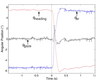
can be seen to have remained remarkably steady, apart from a brisk (45ms) low-amplitude (2.6◦) deviation (see black curve
in fig.4).
Fig. 4. Gaze stabilization in the presence of a sudden perturbation of the robot’s heading (θheading). While the eye was fixating a white-to-dark edge,
a bias step of 11◦ was added to the heading feedback loop (see fig. 7). This caused an immediate counter rotation of the robot’s eye θer, triggered
by the Vestibulo-ocular Reflex (VOR). The robot’s response (θheading) to
this change was completed within about 200ms. The gaze direction (θgaze),
which was obtained by adding together the two curves θheading+ θer, can
be seen to have stabilized efficiently around 0◦, due to the fast and accurate response of the VOR : the gaze strayed outside the ±1◦range for only 45ms,
showing a peak deviation of only 2.6◦. The VOR based on the MEMS rate gyro will stabilize the gaze efficiently regardless of whether the change in the robot’s heading is due to a voluntary saccade or to an external disturbance (such as a gust of wind).
Fig. 5. Frequency analysis of the Vestibulo-ocular Reflex (VOR) showing the ability of the eye to compensate for fast body perturbations. The four curves were recorded in a single experiment where the robot was mounted onto the shaft of a low-friction resolver monitoring its yaw orientation θheading(see
fig.1).(a) Robot’s angular position θheadingresulting from the differential
drive of its two propellers in response to a chirp signal. (b) Resulting eye orientation (plotted here negatively: −θer), which can be seen to counter
the robot’s heading up to high frequencies, thanks to the VOR. (c) and (d) Gain and phase of the transfer function − θer(s)
θheading(s)≈ CV OR(s).Heye(s)
computed from (a) and (b). The gain and phase curves show the fast dynamics of the OSCAR’s VOR, which is able to compensate for any rotational body disturbances over a wide (1 − 7Hz) frequency range.
In the frequency domain, this feedforward control means that the gain and phase of the transfer function relating θer
to −θheading must be held at 0dB and 0◦, respectively, over
the largest possible frequency range, as given by the following expression:
θer
θheading
= −CV OR(s).Heye(s) = −1
No previous studies have focused on artificial VOR-based oculo-motor control systems in a frequency range greater than 2Hz. Here, the frequency response of OSCAR II VOR was assessed over a large frequency band, up to a value of 7Hz, by applying a differential chirp signal to the pro-pellers. This caused the robot to oscillate sinusoidally about its vertical (yaw) axis (θheading in figure 5a) at increasingly
high frequencies. The ensuing rotation of the robot’s eye was measured (−θer in figure 5b) and the magnitude and phase
were calculated (figure 5c and5d) from the ratio between the discrete Fourier transform (DFT) of the output −θer and input
θheading [46]. It can be seen from Figures5c and5d that the
transfer function θ−θer(s)
heading(s) shows zero gain and zero phase
throughout the [1 − 7]Hz frequency range, which makes the performance of this artificial VOR almost comparable to that of the human VOR [47].
2) The visual feedback loop: The visual feedback loop strives to annul the retinal signal error εr to keep the robot’s
gaze locked onto the visual target. The embedded visual sensor measures the retinal error εr in the robot’s reference frame
(the robot therefore does not care whether the visual target is moving or not). The visual sensor’s output εris a linear, even
function of εr = θtarget− θgaze. The visual feedback-loop
makes the robot able to:
• fixate a stationary target
• track a moving target
• correct any low frequency inaccuracies (i.e., drift) of the VOR inertial sensor
The OSCAR II visual sensor [42] has a refresh rate of 10Hz (see details in the AppendixII-B). This 10Hz scanning of the visual scene is the main limiting factor involved in the process of visually rejecting any fast disturbances liable to destabilize the robot. Nonetheless, the VOR reflex solves this problem by greatly improving the dynamics of the gaze stabilization, thus preventing the target from straying beyond the narrow (±1.8◦) FOV of the eye, even in the presence of strong aerodynamic disturbances, as we will see in section IV.
B. The heading control strategy
The “steering by gazing” control strategy is an extension of the eye control strategy depicted in figure 6. In the generic control system shown in figure 7, both the robot’s steering dynamics and the eye dynamics are under the control of the common drive signal Cd ; the gaze control system and
the heading control system are therefore interdependent. Any change in the robot’s heading is treated like an input dis-turbance to the feedback gaze control system. The common drive signal is the difference (Σ2 in Figure 7) between the
VFR and the VOR signals. It drives both the eye (with its
fast dynamics) and the robot (with its slow dynamics). The common drive signal (Cd) acts as a set point for the eye
orientation θer but as an error input signal for the robot’s
heading orientation θheading (see fig. 8). This common drive
signal causes the robot’s body to rotate until its heading is aligned with its gaze (at which time Cd = 0). The
visually-guided behavior implemented here is therefore such that the main output regulated at 0 is the retinal error εr between the
gaze and the orientation of the target (see fig.3). The advantage is that the robot at no time looses sight of the target in the presence of strong disturbances affecting the body, as we will see in section IV-C. The overall system of regulation can be said to first align θgaze with θt(εr= 0) and then to turn the
robot’s body so as to align θheading with θgaze (Cd= 0)
IV. PERFORMANCE OF THEOSCAR IIROBOT
The robot’s performance were tested in three experiments (noted B,C,D below). The first experiment showed the ac-curacy and reliability of the OSCAR II robot equipped with its oculomotor control system and its heading control system. In the second experiment, the visual fixation performance of the robot were compared, depending on whether the Oculo-motor Reflexes (ORs) were activated or inactivated. In the third experiment, the robot’s ability to track a moving target visually was tested in the presence of strong and random aerial perturbations (gusts of wind).
A. Experimental setup
The robot was mounted onto the shaft of a low friction high resolution miniature resolver so that it was free to rotate about its yaw axis. The robot’s heading angle was monitored with a 14-bit resolution (0.022◦) resolver-to-digital converter connected to a dSPACE board. To assess the performance of the visual feedback loop, we presented the robot with a vertical black and white edge that was made to translate horizontally in the frontal plane, 1 meter ahead, via a motorized linear slide system (see Fig. 9). The robot communicated with the computer via a Bluetooth wireless connection emulating a full duplex UART bus. This connection enabled the operator to send the robot high level commands while monitoring the operational variables in real time. The 115.2-Kbaud connection made it possible to monitor up to 6 variables at different sampling rates (Cd, εr, θer, θheading ref, Ωheading, ˆθheading).
The data collected using this UART bus were directly logged in a custom-made Matlab Graphical User Interface (GUI) [49].
B. Visual fixation
Fig.10illustrates the remarkably accurate and steady visual fixation of a stationary edge effected by the OSCAR II robot. Figure 10b shows the histogram distribution of the robot’s heading during the first 30 minutes of a 37-minute long experiment. This histogram shows a Gaussian distribution with a standard deviation as small as σ = 0.14◦. The robot’s heading never strayed beyond ±0.4◦ (which is 4.5 times smaller than the robot’s eye FOV ±1.8◦). In this experiment, the robot kept on holding its gaze (and hence its heading)
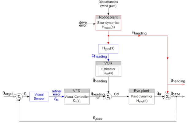
Fig. 6. Block diagram of the Oculomotor Reflexes (ORs). The visual feedback loop at the bottom (which is called the Visual Fixation Reflex (VFR)) is a position servo designed to minimize the retinal error measured εr= θtarget− θgaze, thus making the eye lock onto a contrasting target. The feedforward
controller (VOR) makes the eye compensate exactly for any dynamic changes in the robot’s heading (θheading). In Σ3, the orientation of the robot, θheading,
is added to the eye-in-robot orientation, θer, and in Σ2 the estimated heading ˆθheading is subtracted from the visual controller’s output to hold the gaze
steadily on the target despite any heading disturbances. Note that the robot controls its gaze on the basis of measurements (Ωheading, εr) that relate entirely
to its own coordinate frame: it requires no knowledge of the absolute heading (θheading) or the absolute angular target position (θtarget) shown in Figure3.
Fig. 7. Generic block diagram of the “the steering by gazing” control strategy which involves two intertwined visual (bottom loop) and inertial (upper loop) control system. The system cancels the retinal error signal εrby acting on both θheadingand θer. The three signals θer, Ωheadingand retinal error εr
(in blue) are measured in the robot’s reference frame. None of the angle data available in the laboratory reference frame are conveyed to the controller. This system can be described in terms of Main-Vernier loops [48], where the common drive signal (Cd) provides the (slow) heading feedback-loop with an error
signal and the (fast) eye dynamic loop with a set point signal for controlling the gaze (θgaze). This novel control system meets the following two objectives:
(1) keeping the gaze locked onto the visual (stationary or moving) target whatever aerodynamic disturbances (gusts of wind, ground effects, etc.) affect the robot’s body, and (2) automatically realigning the robot’s heading θheadingwith the gaze, and hence with the visual target.
locked for a total time of 37 minutes (i.e., until the battery was completely empty), in spite of the aerial disturbances caused by its own propellers and the ambient air flow. Figure 10a
shows a 17-second close up sample (from 1000s to 1017s after the start of the experiment) of the robot’s heading (the angle 0◦ corresponds to a perfect alignment of the robot with
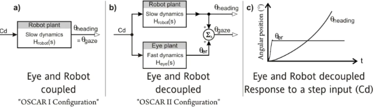
Fig. 8. a) Classical (OSCAR I) robot configuration, where the eye is coupled to the body. b) New (OSCAR II) robot configuration, where the eye is decoupled from the body. In our “Steering by gazing” control strategy, a common drive signal Cdcontrols both the eye and the robot. This common drive
signal is an angular set point for the eye (θer) and an angular error signal for the robot’s heading (θheading). c) Step response of the eye (θer) and that
of the robot’s heading θheading. When serving as an error signal controlling the robot’s (Hrobot), Cdmakes the robot rotate until Cdis cancelled; when
serving as an angular set point controlling the eye (θer), Cdmakes the eye rotate until the appropriate position is reached.
Fig. 9. Sketch of the test bed used to assess the performance of the OSCAR II robot. The robot (see figure1) was free to rotate frictionlessly about its yaw axis. It controls its heading by adjusting the rotational speeds of its two propellers differentially. OSCAR’s gaze locks onto the target (an edge), which can be shifted in the frontal plane 1m ahead. During the tracking experiments, strong aerodynamic perturbations (gusts of wind at speeds of up to 6m/s) were applied asymmetrically (i.e.,onto one propeller) by means of a ducted fan placed 20cm behind the robot.
the target).
Figure 11 stresses the importance of vision in the fixation process by showing that fixation rapidly degrades once the room light has been switched off (at time t=180s). From this moment on, the robot’s heading can be seen to drift by about 2◦within the next 10 seconds. This is due to the drift inherent to the rate gyro, which makes the gaze and hence the heading orientation loose their reference to the edge.
Fig. 10. Long term heading stabilization with respect to the stationary target (placed at the origin θtarget= 0). The OSCAR II robot was mounted
onto the shaft of a low friction miniature resolver that monitored its angular position (see figure 1). The robot, which was free to rotate about its yaw axis, successfully locked its gaze (and its heading) onto a fixed target (see fig.9) during a long (37-minute) experiment. (a) A 17-second sample of the robot’s headingwhile the robot was fixating the target. (b) Distribution of the robot’s heading computed during the first 30 minutes of the experiment. In spite of the natural aerodynamic disturbances, the standard deviation of the heading was very small (σ = 0.14◦).
C. Rejection of aerodynamic perturbations
The previous version of the OSCAR robot (OSCAR I) was prone to be easily destabilized by gusts of wind because its eye was mechanically coupled to its body. OSCAR II is a great improvement over OSCAR I, since the direction of its gaze is decoupled from its heading. The performance of the OSCAR II robot were compared, depending on whether its ORs were activated or not (inactivating the ORs on OSCAR II makes it equivalent to the former OSCAR I configuration, where the eye was fixed to the body). In a preliminary experiment [50], we gave slaps to the robot with a custom made slapping machine. In the current experiment, we used a more natural perturbation. The experimental setup used for this purpose was the same as that described in sectionIV-A, except that a ducted fan was placed 40cm behind one propeller (see figure
9). This fan generated airflow at a speed of 5.2m/s. The airflow perturbation regime was controlled via a PWM signal generated by an acquisition board. To calibrate the ducted fan, various PWM duty cycle values were applied for 10 seconds and the airspeed measured was averaged over this time. To
Fig. 11. Heading drift in the absence of a visual reference. (a) As long as the room light is on, the robot’s heading keeps locking onto the stationary edge (left part, similar to Figure 9a), thanks to the “steering by gazing control strategy” (cf.7). (b) Once the light is switched off (at time index 180s), the visual control loop becomes inefficient (see fig. 7). The retinal error input εrremains null (see the dark curve) causing the robot’s heading to be solely
controlled by the inertial control loop. The robot is unable to hold its heading steady due to the drift inherent to the rate gyro (here, the heading can be seen to drift away inexorably)
compare the performance of the OSCAR II and OSCAR I configurations, both the robot’s heading θheadingand the
“eye-in-robot” orientation θer were measured and the gaze θgaze
were reconstructed as the sum (see fig. 3)
θgaze = θheading+ θer (1)
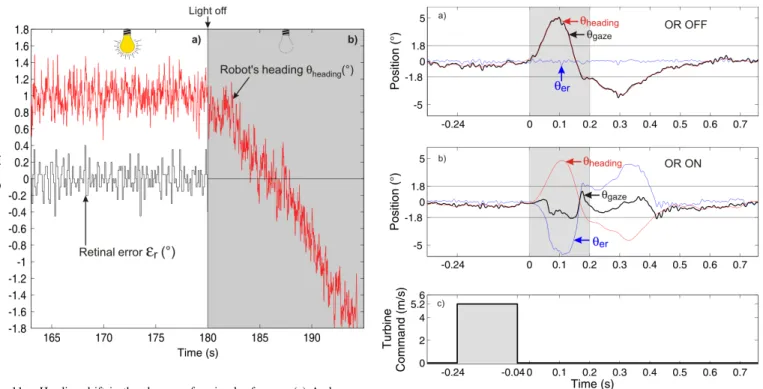
Figure12shows a close up of the robot’s, eye’s and gaze’s responses to the sudden gust of wind in the case of the OSCAR I configuration (fig.12a: Oculo-motor reflexes OFF) and the OSCAR II configuration (fig12b: Oculo-motor Reflex ON). In both experiments, the wind travel time between the turbine and the robot is 240ms. Despite the robot’s inertial feedback controller (see fig.7), the sudden wind gust creates a peak heading error of 5◦. After the 200ms long wind perturbation, the internal integrator compensates for the wind by making the contralateral propeller rotate faster. But when the wind gust stops, the propeller differential speed of rotation makes the robot react in the opposite direction, creating an error of opposite sign −3◦. It can be seen that the heading error lets the target astray from the visual FOV for a total duration of 400ms, in both OSCAR I and OSCAR II configurations. However, in the OSCAR 1 configuration (fig.12a), the gaze (equal to the robot’s heading) leaves the ±1.8◦ limits of the FOV. Visual contact with the target is lost for about 400ms with the dramatic consequence that the robot would loose the target in case of the latter would move during this 400ms period. The OSCAR II configuration by contrast makes the gaze keep within the ±1.8◦FOV limit, the robot always keeps
Fig. 12. (a) and (b) Visual fixation of a steady edge in the presence of a 200ms wind impulse by the OSCAR I configuration (without Oculomotor Reflexes (ORs)) and the OSCAR II configuration (with ORs i.e. Vestibulo-ocular Reflex (VOR) + Visual Fixation Reflex (VFR)). In the OSCAR I configuration, the gaze can be seen to lead astray the ±1.8◦ limit (width
of the FOV). Thus, the target which is steady at the position 0 gets out of the FOV and is lost for almost 400ms (0.03s until 0.4s). In the OSCAR II configuration, the “eye-in-robot” profile (θer blue curve) shows that V OR
immediately counteracts the robot rotation (θheading, red curve), so that the
gaze (θgaze, black curve) remains quasi-steady. This experiment demonstrate
that in the OSCAR II configuration, the robot can maintain visual contact with the visual target despite the strong aerial perturbation applied to its structure.
sight of the target. The mechanical decoupling of the eye associated with fast ORs clearly makes for the robustness of the visual fixation performance, by decreasing the probability for the robot to lose sight of the target.
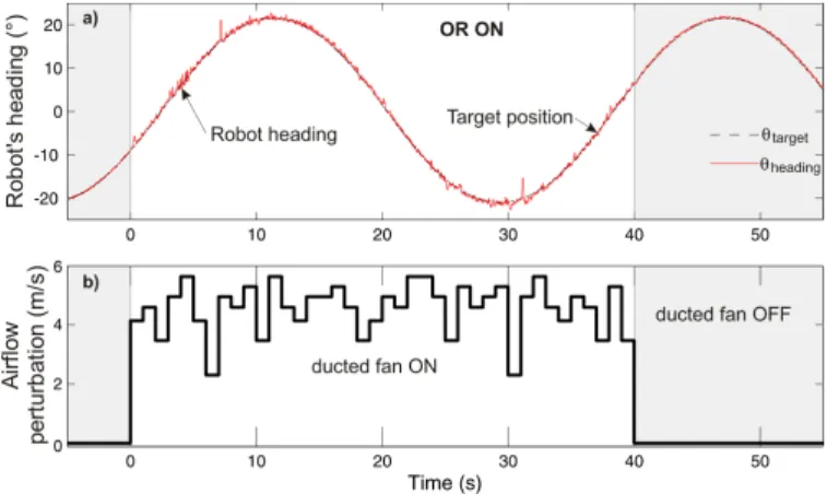
D. Visual tracking of a moving target
To further assess the robustness of the OSCAR II robot in terms of its ability to reject aerodynamic perturbations, the robot was presented with a vertical edge that was made to translate sinusoidally in a frontal plane 1m ahead (see figure
9), and the robot’s visuo-motor behaviour was tested in the presence of strong gusts of wind. The target’s translation was accurately controlled (resolution of 0.125mm) by a stepper motor driven in the microstep mode by a dSPACE board. The translation sequence was a slow sinusoid (period of 36s) of a large amplitude (78cm peak-to-peak, causing an angular excursion of 42.4◦with respect to the robot’s eye). A series of brisk random aerodynamic perturbations was applied here. Figures 13a shows the visual tracking behavior of the OSCAR II robot with its Oculomotor Reflexes (ORs) or ON (Fig.13a) during the visual pursuit of the translating target.
The robot’s heading (red continuous line in figure13a) can be seen to have followed the target throughout the whole cycle; compensating smoothly and accurately for the strong
Fig. 13. (a) Smooth pursuit of a grey edge in the presence of random wind gusts by the OSCAR II configuration (with ORs i.e. Vestibulo-ocular Reflex (VOR) + Visual Fixation Reflex (VFR)). The edge was translated sinusoidally at 0.03Hz with an amplitude of 42.4◦(peak to peak) by means of an accessory linear position servo system (see Fig.9). The maximum linear speed of the target was 6.3cm/s, corresponding to an angular speed of 3.7◦/s. The OSCAR II configuration kept on tracking the visual target consistently despite the aerial perturbations. Theses aerial perturbations sometimes makes the robot’s heading to get away from the visual target by an error angle greater than the FOV (1.8◦). However, the fast V OR maintains the gaze locked onto the visual target (see details on fig.12). Maintains the visual contact with the target made the robot faithfully follow the target.
random gusts of wind applied to one of its propellers (from 0s to 40s) and never loosing sight of the moving target. Each pulse of wind gave rise to the same kind of reaction as shown in fig. 12b. This attests that when the ORs are activated the robot manages to reject the strong aerodynamic perturbations robustly throughout the cycle with its gaze locked onto the moving target (fig. 13a).
V. CONCLUSION
The 100-g aerial demonstrator presented here is equipped with an accurate one-axis ultra-fast gaze and heading control system mimicking the highly proficient visuomotor processes at work in natural flying creatures. This system was designed to keep the robot heading stably towards a contrasting edge, despite the severe aerodynamic perturbations imposed on its body. The key to this achievement is the mechanical decou-plingbetween eye and body. The robot’s eye, which performs similar micro-scanning movements to that known to occur in flies, can be said to be a hyperacute optical Position Sensing Device (PSD) with a very limited Field Of View (FOV) (±1.8◦) [43]. Although this FOV is of a similar size to that of the human fovea, it requires only two pixels, as opposed to six million pixels. The main advantage of this minimalistic device over the visual systems classically used on robotic platforms is that it requires very few computational resources, which makes it possible to mount the whole visuo-motor processing system onboard a small aerial robot. The possible drawbacks of having such a small FOV are compensated for by the additional degree of freedom from which the robot’s eye benefits by having its gaze oriented independently of its body. The fast dynamics of the eye boost the two oculomotor reflexes which consist of:
• a Visual Fixation Reflex (VFR)
• a Vestibulo-ocular Reflex (VOR)
The fast inertial VOR stabilizes the robot’s gaze when the robot’s body is subjected to untoward perturbations. Whenever the robot’s heading is affected by a rotational disturbance, the change in θheading is measured and compensated for by the
VOR feedforward control system, which immediately triggers an appropriate counter rotation of the eye. The VOR is coupled with the VFR. The VFR endows the robot with the ability to fixate a stationary target at high accuracy for a long time (e.g. 30 min in fig.10) and to track a moving target accurately without being disturbed by strong gusts of wind (figure13b). The robot tracks a moving target as robustly as it fixates a stationary target because the VOR consistently compensates for all the disturbances to which the body is exposed. The visual fixation reflex also compensates for the inevitable drift of the rate gyro (which is used to measure the robot’s yaw speed Ωheading).
The fast dynamics of the eye (rise time as small as 19ms, fig.
15) enable it to perform fast and accurate saccadic movements. Saccades, which have been studied in detail in humans, monkeys, and many insects, make it possible to orient the fovea onto a new target. This will be the subject of our further studies. We will now describe how saccadic movements can coexist with the oculomotor performance described above. In the “steering by gazing” control strategy presented here, the ro-bustness of the gaze control system can be said to be extended to the heading control system. An aerial vehicle equipped with this system would be able to reject the aerodynamic dis-turbances encountered and to eventually realign its trajectory with the target on which the gaze remains firmly locked. This visuo-inertial heading control strategy is one step towards the development of autonomous Unmanned Air Vehicules (UAVs) and Autonomous Underwater Vehicles (AUVs). The lightness and low power consumption of the whole system would make it particularly suitable for application to Micro-Air Vehicles (MAVs) and Micro-Underwater Vehicles (MUVs) which are prone to disturbances due to untoward pitch variations, wing-beats (or body undulations or fin-wing-beats), wind gusts (or water streams), ground effects, vortices, and unpredictable aerody-namic (or hydrodyaerody-namic) disturbances of many other kinds. Lessons learned from biological creatures teach us that it is best to compensate early on for these disturbances, which was done here by using a visuo-inertial gaze stabilization system as the basis for efficient heading stabilization. Anchoring the gaze on a contrasting feature in the environment provides a robust, drift-freestarting-point for exploring the world.
APPENDIXA LOCAL CONTROLLERS
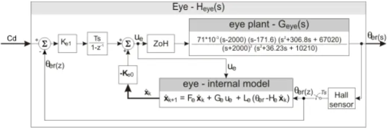
A. Control of the robot’s eye orientationθer
The dynamics of the human oculomotor system result in performance that are often said to be contradictory. On the one hand, the Extra Ocular Muscles (EOM) keep he gaze accurately fixed on a steady target [51]; and on the other hand, these muscles rotate the eye at high speed: a saccade of moderate amplitude is triggered within only about 100ms [52].
We mimicked the high performance of the human oculomo-tor system by using an unconventional “extra-ocular muscle”
Fig. 14. Block diagram of the oculo-motor control system, which servoes the “eye-in-robot” angle θerto the reference input Cd(see figure [43]). The eye’s
internal state space model uses both the command Ue(z) and the measured
angle θer(z) to estimate the four internal states of the system that include
the eye and its VCM actuator. The fifth external state is the integral of the eye’s position error, which insures a zero steady state error. The classical LQG method was used to compute the gain matrix Ke0and Ke1.
to control the orientation of the OSCAR’s eye-tube: this device consisted of a micro Voice Coil Motor (VCM) milled out of a hard disk microdrive (Hitachi or Magicstor microdrives gave equally satisfactory performance). This VCM, which was designed to control the read/write head in disk drive control systems [53], was used here to good effect to rotate the eye (see figure 3), because it gave a good trade-off between high accuracy and fast rotation. Controlling a VCM requires a position feedback loop. The robot’s visual angle θer(see fig.3)
is measured by a Hall sensor placed in front of a micro magnet (1mm3) glued to the eye-tube’s rotational axis (fig.2). A state
space approach was used to implement a controller composed of an estimator cascaded with a state-augmented control gain Ke computed using a classical LQG method. This structure
servoes the θer angle to the reference input Cd (Fig.7,8and
14 ). The state space approach adopted here gave fairly good results, despite the non-linearity of the eye plant (which was approximated by the linear model Geye(s): see C) and the
background noise present in the Hall sensor’s output signals.
Fig. 15. Closed-loop step response of the “Eye-in-Robot” angular position θer to a large (10◦) step input applied to the reference input Cd (Fig.7, 8 and14). The Voice Coil Motor (VCM) actuator (see fig.3) is controlled via a full state feedback controller which gives a settling time (Tsettle) as
small as 29ms. θer is measured by the Hall effect sensor placed in front of
a micro-magnet mounted onto the eye axle (fig.2).
The step response illustrated in Fig.15shows the very fast dynamics obtained with this closed-loop control of the “Eye-in-Robot” orientation: θer. A rise time Trise as small as 19ms
and a settling time Tsettle as small as 29ms were obtained
(as compared to 44ms in the original version: see figure 4 in [50]). In response to a large 45-deg step (not shown here), a velocity peak of 2300◦/s was reached, which is about four times higher than the 660◦/s peak reached by our former (PID) controller [50] and three times higher than the saturation velocity (600◦/s) of the human eye measured during a saccade [54]. On the whole, the robot’s oculomotor control system is practically linear, unlike the human oculomotor control system (the rise time of which typically increases with the saccade amplitude [52]).
B. Controlling the robot’s heading θh
Here again, a state space structure was used to control the robot’s heading (figure16). The robot’s state space controller is a simplified three-state model, to which an external integral state has been added. The additional integral state compen-sates for any mismatch in propeller efficiency and ensures a zero steady state error, thanks to the robustness of the LQR compensator that can cope with any non-linearities that were not initially modeled.
Fig. 16. Block diagram of the robot’s heading controller. The robot’s inner controller consists of a three-state estimator combined with a classical full state feedback law with an additional integral state. The classical LQG method was used to compute the gain matrix Kr0and Kr1.
APPENDIXB
THE HARDWARE ARCHITECTURE
A. Description of the robot electronics
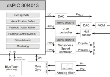
A photograph of the main electronic board is shown in fig.18. The digital electronics embedded in the robot are composed of the main microcontroller (dsPIC 30f4013) su-pervising two smaller microcontrollers (dsPIC 30f2010) (see fig.17). One of the latters controls the rotational speed of each propeller in the closed loop mode (it is part of the 1-gram dual channel speed controller board described in [39]). The other one controls the angular position of the eye θer in the closed
loop mode, according to the scheme shown in Fig.14, and drives a power analog amplifier connected to the VCM.
The main dsPIC 30f4013 is in charge of :
• extracting the retinal error εrusing an Elementary Motion
Detector (EMD)
• estimating the robot’s heading ˆθheading via the MEMS
rate gyro
• implementing the Visual Fixation Reflex (VFR)
Fig. 17. Simplified scheme of the embedded electronics. The robot is equipped with three Microchip dsPIC microcontrollers. The main micro-controller (dsPIC 30F4013) runs a multirate simulink-based program, which is in charge of the main control tasks. Two secondary microcontrollers (dsPIC 30f2010) are used to control the eye’s orientation and the propellers respectively. The main microcontroller sends the set point specifying both the eye’s angular position and the throttle of the two propellers via PWM signals. It receives two analog signals (Ph1 and Ph2) from the eye’s retina and sends an analog signal controlling the retinal micro-scanning movement to the piezo driver. A Bluetooth wireless device connected to the UART peripheral can be used by the operator to log data received from the freely moving robot and to send the robot data and start/stop instructions. This radio link also serves to reprogram the main microcontroller via the tinybld bootloader [55].
• implementing the steering control system
• driving the Piezo eye actuator
The main dsPIC therefore manages both kinds of sensory input: the visual input (the two photodiode signals) and the inertial input (the rate gyro). It also drives a high voltage amplifier used to control the piezo bender responsible for the retinal microscanning process [40]. The Bluetooth device provides a full-duplex radio link between the robot and the Matlab-PC ground station. This radio link makes it possible to remotely monitor the various variables and to reprogram the main digital controller (dsPIC 30f4013).
All embedded algorithms were developed with a custom-made Simulink blockset for dsPIC [49]. This tool can program the Microchip embedded digital controller directly from a Simulink model without having to type any code lines.
APPENDIXC TRANSFER FUNCTIONS
Fig. 18. The autopilot board of the OSCAR 2 robot. This board comprises the main microcontroller (dsPIC 30f4013) and the rate gyro (ADIS16100). All the board’s inputs and outputs are electrically isolated from the other devices (the piezo driver, VCM and sensorless speed controllers, cf. figure 15). The board is powered by a small 3.6V-100mAh (LiPo) battery.
ACKNOWLEDGMENT
The authors acknowledge the assistance of M. Boyron for designing and producing the miniature electronic boards used here, including the piezo driver, the EMD and the control systems. We thank F. Paganucci and Y. Luparini for their help with the mechanical construction of the eye and the robot and F. Ruffier and J. Serres for fruitful discussions and comments on the manuscript. The research leading to these results has received funding from CNRS and University of the Mediterranean, the French National Research Agency (ANR, RETINAE project) and the French Armament Procurement Agency (DGA) under contract n0534022.
REFERENCES
[1] J.-C. Zufferey, Bio-inspired Flying Robots: Experimental Synthesis of Autonomous Indoor Flyers, , Ed. Lausanne: EPFL/CRC Press, 2008. [Online]. Available:http://book.zuff.info
[2] A. Beyeler, J.-C. Zufferey, and D. Floreano, “Vision-based control of near-obstacle flight,” Autonomous Robots, vol. 27, no. 3, pp. 201–219, Oct. 2009.
[3] J. Conroy, G. Gremillion, B. Ranganathan, and J. Humbert, “Implementation of wide-field integration of optic flow for autonomous quadrotor navigation,” Autonomous Robots, vol. 27, no. 3, pp. 189–198, Oct. 2009. [Online]. Available: http://dx.doi.org/10.1007/ s10514-009-9140-0
[4] T. S. Collett and M. F. Land, “Visual control of flight behaviour in the hoverfly Syritta pipiens l.” Journal of Comparative Physiology A, vol. 99, no. 1, pp. 1–66, Mar. 1975.
[5] R. Kern and D. Varjù, “Visual position stabilization in the hummingbird hawk moth, Macroglossum stellatarum L.” J Comp Physiol A 182, pp. 225–237, 1998.
[6] N. Boeddeker, R. Kern, and M. Egelhaaf, “Chasing a dummy target: smooth pursuit and velocity control in male blowflies,” in Proc. R. Soc. Lond.B 270, 2003, pp. 393–399.
[7] M. F. Land and T. S. Collett, “Chasing behaviour of houseflies (fannia canicularis),” Journal of Comparative Physiology A, vol. 89, no. 4, pp. 331–357, Dec. 1974.
[8] R. M. Olberg, A. H. Worthington, and K.R.Venator, “Prey pursuit and interception in dragonfly,” J Comp Physiol A186, pp. 155–162, 2000. [9] J. H. V. Hateren and C. Schilstra, “Blowfly flight and optic flow. ii. head
movements during flight,” J. Exp Biol, vol. 202, pp. 1491–1500, 1999. [10] J. Zeil, N. Boeddeker, and J. M. Hemmi, “Vision and the organization
[11] D. Sandeman, “Head movements in flies (Calliphora) produced by deflexion of the halteres,” J Exp Biol, vol. 85, no. 1, pp. 43–60, Apr. 1980. [Online]. Available: http://jeb.biologists.org/cgi/content/abstract/ 85/1/43
[12] R. Hengstenberg, “Mechanosensory control of compensatory head roll during flight in the blowfly Calliphora erythrocephala meig,” J. Comp Physiol A, vol. 163, pp. 151–165, 1988.
[13] ——, “Control of head pitch in Drosophila during rest and flight,” in Proc. of 20th Göttingen Neurobiology Conference G. Thieme Verlag, Stuttgart. Elsner N., Richter D. (eds), 1992, p. 305.
[14] D. H. Ballard, “Reference frames for animate vision,” in Proc. 2nd Int’l. Congress of Neuroethology, Berlin, September 1989, pp. 1635–1641. [15] F. Du, J. M. Brady, and D. W. Murray, “Gaze control for a two-eyed
robot head,” in Proc 2nd British Machine Vision Conference, Glasgow. London: Springer-Verlag, 1991, pp. 193–201.
[16] N. J. Ferrier and J. C. Clark, “The Harvard binocular head,” International Journal of Pattern Recognition and Artificial Intelligence, vol. 7, no. 1, pp. 9–31, 1993.
[17] T. Yamaguchi and H. Yamasaki, “Velocity based vestibular-visual in-tegration in active sensing system,” in Proc. IEEE Intern. Conf. on Multisensor Fusion and Integration for Intelligent Systems, Las Vegas, USA, 1994, pp. 639–646.
[18] T. Shibata and S. Schaal, “Biomimetic gaze stabilization based on feedback-error learning with nonparametric regression networks,” Neu-ral Networks, vol. 14, pp. 201–216, 2001.
[19] F. Panerai, G. Metta, and G. Sandini, “Learning visual stabilization reflexes in robots with moving eyes,” Neurocomputing, vol. 48, pp. 323– 337, 2002.
[20] A. Lenz, T. Balakrishnan, A. G. Pipe, and C. Melhuish, “An adaptative gaze stabilization controller inspired by the vestibulo-ocular reflex,” IOP Bioinspiration & Biomimetics, vol. 3, p. 035001, 2008.
[21] A. Lewis, “Visual navigation in a robot using zig-zag behavior,” in Proceedings of Neural Informations Processing Systems (NIPS), 1997, pp. 822–828.
[22] P. Viola, “Neurally inspired plasticity in oculomotor processes,” in Proceedings of Neural Information Processing Systems (NIPS), 1989, pp. 290–297.
[23] J.-A. Meyer, A. Guillot, B. Girard, M. Khamassi, P. Pirim, and A. Berthoz, “The Psikharpax project: towards building an artificial rat,” Robotics and Autonomous Systems, vol. 50, no. 4, pp. 211–223, Mar. 2005. [Online]. Available:http://www.sciencedirect.com/science/article/ B6V16-4F3NY1T-2/2/ec53ab956f362ced1629259454a1f68a
[24] R. Miyauchi, N. Shiroma, and F. Matsuno, “Compact image stabilization system using camera posture information,” J. Field Robot., vol. 25, no. 4-5, pp. 268–283, 2008.
[25] X. Twombly, R. Boyle, and S. Colombano, Active Stabilization of Images Acquired on a Walking Robotic Platform. G.Bebis et al. (Eds.), ISVC 2006, LNCS 4292, 2006, pp. 851–860.
[26] R. Wagner, I. W. Hunter, and H. L. Galiana, “A fast robotic eye/head system: Eye design and performance,” in Proc. of IEEE Engineering in Medicine and Biology Society, vol. 14, 1992, pp. 1584–1585. [27] E. Maini, L. Manfredi, C. Laschi, and P. Dario, “Bioinspired velocity
control of fast gaze shifts on a robotic anthropomorphic head,” Autonomous Robots, vol. 25, no. 1, pp. 37–58, Aug. 2008. [Online]. Available:http://dx.doi.org/10.1007/s10514-007-9078-z
[28] S. Takizawa, S. Ushida, T. Okatani, and K. Deguchi, “2dof motion stabilization of biped robot by gaze control strategy,” in Intelligent Robots and Systems, 2005. (IROS 2005). 2005 IEEE/RSJ International Conference on, 2-6 Aug. 2005, pp. 1102–1107.
[29] S. Ushida, K. Yoshimi, T. Okatani, and K. Deguchi, “The importance of gaze control mechanism on vision-based motion control of a biped robot,” in Intelligent Robots and Systems, 2006 IEEE/RSJ International Conference on, Oct. 2006, pp. 4447–4452.
[30] N. J. Strausfeld, H. S. Seyan, and J. J. Milde, “The neck motor system of the fly Calliphora erythrocephala. 1. muscles and motor neurons,” J. Comp. Physiol, vol. A 160, pp. 205–224, 1987.
[31] E. L. Keller, “Gain of the vestibulo-ocular reflex in monkey at high rotational frequencies,” Vis. Res., vol. 18, pp. 311–115, 1978. [32] M. Huterer and K. E. Cullen, “Vestibuloocular reflex dynamics during
high-frequency and high acceleration rotations of the head on body in rhesus monkey,” J Neurophysiol, vol. 88, pp. 13–28, 2002.
[33] R. W. Clifford, P. C. Know, and G. N. Dutton, “Does extraocular muscle proprioception influence oculomotor control ?” Br. J. Ophtalmol, vol. 84, pp. 1071–1074, 2000.
[34] N. Dancause, M. D. Taylor, E. J. Plautz, J. D. Radel, T. Whittaker, R. J. Nudo, and A. G. Feldman, “A stretch reflex in extraocular muscles of
species purportedly lacking muscle spindles,” Exp Brain Res, vol. 180, pp. 15–21, 2007.
[35] T. Preuss and R. Hengstenberg, “Structure and kinematics of the prosternal organs and their influence on head position in the blowfly Calliphora erythrocephala meig,” J Comp Physiol A 171, pp. 483–493, 1992.
[36] A. Paulk and C. Gilbert, “Proprioceptive encoding of head position in the black soldier fly, Hermetia illucens (l.) (Stratiomyidae),” The Journal of Experimental Biology, vol. 209, pp. 3913–3924, 2006.
[37] E. Liske, “The influence of head position on the flight behaviour of the fly, Calliphora erythrocephala,” J. Insect Physiol, vol. 23, pp. 375–179, 1977.
[38] S. Viollet and N. Franceschini, “Visual servo system based on a biologically-inspired scanning sensor,” in Sensor fusion and decentral-ized control in robotics II, SPIE, vol. 3839, Boston, 1999, pp. 144–155. [39] S.Viollet, L. Kerhuel, and N. Franceschini, “A 1-gram dual sensorless speed governor for micro-air vehicles,” in Proc. IEEE MED’08, Ajaccio, France, 2008, pp. 1270–1275.
[40] S. Viollet and N. Franceschini, “A high speed gaze control system based on the vestibulo-ocular reflex,” Robotic and Autonomous System, vol. 50, pp. 147–161, 2005.
[41] N. Franceschini and R. Chagneux, “Repetitive scanning in the fly compound eye,” in Göttingen Neurobiol. Conf., Göttingen, 1997, p. 279. [42] S. Viollet and N. Franceschini, “Biologically-inspired visual scanning sensor for stabilization and tracking,” in Proceedings of IEEE IROS’99, Kyongju, Korea, 1999, pp. 204–209.
[43] ——, Super-accurate visual control of an aerial minirobot, in: Au-tonomous Minirobots for Research and Edutainment AMIRE. Pad-derborn, Germany: U. Ruckert, J. Sitte and U. Witkowski (Eds), 2001. [44] G. Westheimer, Visual hyperacuity. Berlin: Ottoson, Sensory
Physiol-ogy 1, Springer, 1981.
[45] R. H. S. Carpenter, Movements of the eyes, 2nd edt. PION, London, 1988, ch. 2 : Vestibular eye movements.
[46] G. Franklin, J. Powel, and M. Workman, Digital Control of Dynamic Systems - 3rd ed. Addison Wesley, 1998.
[47] G. B. Gauthier, J. P. Piron, J. P. Roll, E. Marchetti, and B. Martin, “High-frequency vestibulo-ocular reflex activation through forced head rotation in man.” Aviat Space Environ Med, vol. 55, no. 1, pp. 1–7, Jan 1984.
[48] B. Lurie and P. Enright, Classical feedback control with Matlab, ser. Control Engineering, M. Dekker, Ed. Marcel Dekker, 2000. [49] L. Kerhuel, “Pic and dspic rapid prototyping blockset for simulink,”
October 2008. [Online]. Available:http://www.kerhuel.eu
[50] L. Kerhuel, S. Viollet, and N. Franceschini, “A sighted aerial robot with fast gaze and heading stabilization,” in Proc. of IEEE Conf on Intelligent Robots and Systems (IROS), San Diego, CA, USA, October 2007, pp. 2634–2641.
[51] R. M. Steinman, “Voluntary control of microsaccades during maintained monocular fixation,” Science, vol. 155, pp. 1577–1579, 1967. [52] W. Becker, Vision and visual dysfunction (Vol 8). GR.H.S. Carpenter
(Ed) Macmillan Press, Ltd, 1991, ch. 5 : Saccades, pp. 95–137. [53] B. M. Chen, T. H. Lee, K. Peng, and V. Venkataramanan, Hard Disk
Drive Servo Systems 2nd Edition. Springer, Berlin, 2006.
[54] D. Robinson, “The mechanics of human saccadic eye movement,” Physiology London, vol. 174, pp. 245–264, 1964.
[55] C. Chiculita, “Tiny pic bootloader,” October 2008. [Online]. Available:
http://www.etc.ugal.ro/cchiculita/software/picbootloader.htm
Lubin Kerhuel was born near Paris, France. He graduated in microelectronics and received a mas-ter in signal processing and numerical communica-tion from the University of Nice Sophia-Antipolis, France. He worked for one year in the Neuroscience Sensorimotor Network Laboratory (LNRS), in Paris, studying inner ears through invasive experimenta-tions and behavioural studies. He received the PhD in automatics and microelectronics from the Mont-pellier II University, France, from his works on bio-inspired visual sensor and gaze-stabilisation done in the biorobotics lab, Marseille. He developed a simulink blockset for targeting microcontrollers worldwide used. He is interested in the control of minimalist aerial vehicle, helicopter or flying wing, based on visual and/or inertial sensors.
Stéphane Viollet was born in Limoges, France. He received the Master’s degree in control engineer-ing from the University of Bordeaux 1,Bordeaux, France, and the Ph.D. degree from the National Polytechnic Institute, Grenoble, France, in Septem-ber 2001. He is currently a Permanent Research Scientist with the Biorobotics Laboratory, Institute of Movement Sciences, National Center for Sci-entific Research/University of the Mediterranean, Marseille, France. His current research interests in-clude biorobotics, oculomotor control, and retinal micromovements, as well as the development of novel bioinspired visual sensors and control laws for implementation onboard autonomous flying robots.
Nicolas Franceschini was born in Mâcon, France. He graduated in electronics and control theory and received the Ph.D. degree in physics from the Na-tional Polytechnic Institute, Grenoble, France. For nine years, he was with the Max-Planck Institute for Biological Cybernetics. In 1979, he created the Neurocybernetics Laboratory,National Centre for Scientific Research, Marseille, France, and later cre-ated the Biorobotics Laboratory. His current research interests include visual sensors, in particular optic flow sensors, retinal micromovements, oculomotor control, head control, and flight control systems and their potential applica-tions to air and space vehicles.