HAL Id: inria-00528840
https://hal.inria.fr/inria-00528840v2
Submitted on 2 Nov 2010HAL is a multi-disciplinary open access
archive for the deposit and dissemination of sci-entific research documents, whether they are pub-lished or not. The documents may come from teaching and research institutions in France or
L’archive ouverte pluridisciplinaire HAL, est destinée au dépôt et à la diffusion de documents scientifiques de niveau recherche, publiés ou non, émanant des établissements d’enseignement et de recherche français ou étrangers, des laboratoires
Resiliency in Distributed Workflows
Laurentiu Trifan
To cite this version:
Laurentiu Trifan. Resiliency in Distributed Workflows. [Research Report] RR-7435, INRIA. 2010, pp.42. �inria-00528840v2�
Resiliency in Distributed Workflows
Laurentiu TRIFAN
N° 7435
Resiliency in Distributed Workflows
Laurentiu Trifan
Theme 1: Computational Models and Simulation
OPALE Project
Research Report n
o7435 -- October 2010 – 42 pages
Abstract: In this report we present a thorough study of the concept of resiliency in distributed workflow systems. We focus particularly in applying this concept in fields like numerical optimization, where any software or logical error could mean restarting the entire experiment. A theoretical study is presented along with a set of software tools for implementation directions. At the end a resilient algorithm schema is proposed for later refinement and implementation.
Key-words: Workflow, Resiliency, Distributed Systems, Fault Prediction
Centre de recherche INRIA Grenoble – Rhône-Alpes 655, avenue de l’Europe, 38334 Montbonnot Saint Ismier Téléphone : +33 4 76 61 52 00 — Télécopie +33 4 76 61 52 52
La résilience dans les systèmes de workflow distribués
Laurentiu Trifan
Thème 1: Modèles de Calcul et Simulation
Projet OPALE
Rapport de Recherche n
o7435 -- Octobre 2010 – 42 pages
Résumé: Dans ce rapport, nous présentons une étude approfondie de la notion de
résilience dans les systèmes de workflow distribué. On a comme objectif particulier l'application de ce concept dans des domaines comme l'optimisation numérique, dont les erreurs des logiciels ou logiques pourraient signifier le redémarrage de l'expéri-ence entière. Une étude théorique est présentée avec un ensemble d'outils logiciels pour la mise en œuvre. En fin, un schéma d'un algorithme de résilience est proposé pour être raffiné et mise en œuvre plus tard.
Mots-clés: Workflow, Résilience, Systèmes Distribués, Prédiction des Fautes
Centre de recherche INRIA Grenoble – Rhône-Alpes
655, avenue de l’Europe, 38334 Montbonnot Saint Ismier Téléphone : +33 4 76 61 52 00 — Télécopie +33 4 76 61 52 52
1 Introduction
The design and implementation of large scientific applications, corroborated with the large demand for computational power has led to continuously growing HPC sys-tems under the form of GRID infrastructures or clusters of computing nodes. These applications imply processing of large data sets, control flow management and execu-tion on distributed resources. To fill the gap between non-experimented scientists playing the role of users and the complexity of these large distributed systems, the need for user environments easy to configure and deploy has increased considerably [3, 13, 15, 21]. To achieve this, the HPC research community is showing a great inter-est in workflow systems. These systems provide solutions for facilitating the access to large distributed infrastructures for scientists working in domains like Bio-Informat-ics, Forecast, Pharmacy, Aeronautics and Automobiles, etc.
Departing from the ideas mentioned above, the purpose of this thesis is to build a high performance environment to be used in multidisciplinary optimization field, taking into consideration the aforementioned concepts. Design and modeling tools are distributed across different teams working in common projects but collaborating from different geographic zones. The purpose of the collaborative platform is to group all these tools under a common environment and put them at scientists' disposition by means of user friendly interfaces. Giving the distributed nature of the tools, computa-tions are also performed in a distributed manner so the platform has to take into ac-count the parallelism, asynchronous execution of tasks, fast data transfer, fault toler-ance and software resiliency [1, 15, 16, 24]. If some of these properties are already provided by the software tools we are planning to use in the platform's constitution, there are other properties not implemented yet. The originality of this thesis will reside in a deeper research study on fault tolerance and more specifically, software resilien-cy. If at hardware and system levels the fault tolerance concept has been thoroughly studied and precise implementations exist [6, 24, 27, 31], our aim is to raise the con-cept to the design and software levels. Thus we want to provide the collaborative plat-form with a resiliency system. This assures the execution of scientific experiments in a safe manner with capabilities of recovery from algorithm design errors, bad parameter values, infinite loops, service non-availability, etc.
There are a lot of workflow systems nowadays [3, 15, 21], some of them being open source like Taverna, Pegasus, Triana, YAWL, etc. For reasons explained later on, our focus has stopped on the YAWL system which we believe answers the best to our demands. Even if YAWL was designed to address business process management issues, its features providing dynamism and flexibility in execution and exception treatment weighted greatly in our decision.
In the next sections we present the theoretical aspects of the resiliency and at what level has been studied in the literature (section 2). We insist on the directions that we think are important to allocate more research study. Then we give a detailed presentation of the tools that we use to build the collaborative platform and also to test it on real scientific experiments (section 3). Having both the theoretical and practi-cal aspects exposed, the challenge is to present a strategy of
merging them together in what will be a collaborative platform. Next we come up with a schema of a resiliency algorithm, that is the goal of the project, and in the end some conclusions are drawn.
2 Theoretical Study
2.1 Taxonomy of fault tolerance in Workflow Management Systems
At the highest level Workflow systems can be characterized by a two levels ar-chitecture:
✗ Build Time level – concerned with user management and with defining and modeling workflow tasks and their dependencies.
✗ Run Time level – concerned with managing workflow executions and interac-tions with grid infrastructures through external services.
Users interact with workflow modeling tools to generate a workflow specifica-tion, which is submitted to a run-time service, often known as the workflow engine, for execution. By studying the different Grid workflow systems proposed in the recent past [3, 15, 18, 21], a set of architectural styles and designs, and engineering similari-ties (and differences) can be deduced. In the rest of this section we will present a tax-onomy of Grid workflow systems by emphasizing the fault tolerance aspect of such systems.
When executing a scientific application on a Grid infrastructure through a work-flow system, failures can occur for various reasons: hardware/system failures (network failures, resource non-availability, system out of memory) but also application failures (faulty algorithm, infinite loops, inadequate parameter values, stack overflow, runt-time exception, programming bug). The first type of failures are mostly treated by the middle-ware layer residing between the workflow environment and the Grid infra-structure. Grid workflow systems should be able to identify and handle errors and sup-port reliable execution no matter the type of failure. The different error handling pro-cedures can be divided into two main categories: task-level and workflow-level tech-niques [3]. Task-level techtech-niques mask the effects of the execution failure of tasks in the workflow, while workflow-level techniques manipulate the workflow structure such as execution flow, to deal with erroneous conditions. The main task-level tech-niques are the following:
✗ Retry – is the simplest recovery technique, as it simply tries to execute the
same task on the same resource after failure occurrence.
✗ Checkpoint/Restart – an application/task is progressively restarted from the
last good checkpoint (if available) on different resources in case of failures. The migration algorithm determines the best migration path [25, 26, 27].
✗ Replication (or over-provisioning) – is a fault tolerance mechanism where multiple copies of an application (with the same input data set) are executed in parallel. The idea is to maximize the probability of success for the application/task so that if one copy fails then another copy may succeed. This is particularly important in the presence of unreliable resources and where missing a deadline may incur a high penalty. The over-provisioning algorithm determines the best set of resources to replicate the application/task.
The above mentioned fault tolerant techniques are mostly dedicated to hardware and system failures. They can also be used for application failures but their efficiency can prove to be very weak. Here is a set of reasons for which more advanced recovery techniques grouped in the concept of resiliency have to be developed that could ad-dress this type of failures [6]:
✗ If a task fails, not because of a resource failure, but because of a failure in the task itself (e.g. run-time exception or programming bug), using the retry or migration recovery techniques will only waste valuable resources without hav-ing a chance to successfully complete.
✗ The amount of data needed to be check-pointed and the expected rate of faults for petascale and larger systems are already exposing the inadequacies of tra-ditional checkpoint/restart techniques.
✗ The most common parallel programming model, MPI, does not offer a para-digm for resilient programming. A failure of a single task often leads to the killing of the entire application. An exception is the MPI implementation for volatile resources (MPICH – V) [38].
✗ Most applications and system software are not fault tolerant nor fault aware and are not designed to confine error/faults, to avoid or limit their propaga-tion, and to recover from them when possible (except in limited cases).
✗ There is no communication or coordination between the layers of the software stack in error/fault detection and management, nor coordination for preventive or corrective actions.
✗ Errors, fault root causes, and propagation are not well understood.
✗ There is almost never verification of the results from large, long running scale simulations.
✗ There are no standard metrics, no standardized experimental methodology, nor standard experimental environment to stress resilience and compare them fair-ly.
The workflow system should be able to monitor the application's execution and detect any software error, treat it (if possible) and continue the execution in a safe manner. Since this type of failures didn't benefit of wide studies and experiments like the hardware/system failures, the research agenda should follow mainly two important tracks as stated in [6]:
✗ Extend the applicability of rollback toward more local recovery, reducing checkpoint size, error and fault confinement, dynamic error handling by applications.
✗ Fault avoidance and fault oblivious software to limit the recovery from rollback, situation awareness, system level fault prediction for time opti-mal check-pointing and migration.
In the next sub-sections we will present some guideline methods of how to pur-sue this research agenda by making use of dynamic properties, exception handling techniques and simulation based behavior prediction.
2.2 Taxonomy of Dynamicity in Workflow Systems
Scientific research is exploratory by nature. This means that a scientist can not predict from the design phase all the scenarios that his experiments will follow during execution. Instead when formulating experiments as scientific workflows, the scientist can design an initial workflow and subsequently test it with different combinations of parameters and process adaptation until a suitable solution is found. But in a static im-plementation of the workflow system this would mean restarting the whole experiment from the beginning each time a design modification or a modified parameter value is tested [14]. To avoid this overhead, the system must be flexible and accept change during run-time, thus continuing the initial thread of execution. Also in some cases, the tasks to be performed or parameters to be used at a certain point may be so depen-dent on the results provided by the previous tasks that it does not make any sense to try to preview them. The most desirable solution would be to enable the specification of the next task and their inter-dependencies as soon as the current task has finished. Nowadays, the application of computational technologies to new problems and the need to get more accurate outcomes demand the use of updated (and in some cases real-time) data inputs. The Dynamic Data Driven Application Systems (DDDAS) [2] concept entails capabilities where application simulation can dynamically accept and respond to field - data and measurements. Nevertheless, final computations and data management are going to be performed on real resources. This can involve issues such as availability, capacity, performance
limita-tions that could prevent the normal execulimita-tions of the experiment. Having a system that can address dynamically all these faulty scenarios, significantly improves the perfor-mances. Also going further, dynamicity can be a great tool to address faulty design er-rors (by modifying the thread of execution at run-time, or changing parameters' val-ues), programming errors, or other type of application errors, thus contributing to the resiliency of the system.
Dynamicity in workflow systems has introduced many requirements that can be grouped into two main categories [2]: change requirements (addressing changes to be done during scientific workflow execution) and usability requirements (how to facili-tate the performance of such changes). Here is a brief analysis of specific solutions to meet these requirements for each type.
Change Requirements:
✗ CR-1: Changes in the Workflow Abstract Description ✗ CR-2: Changes in the Abstract-To-Concrete Transformation ✗ CR-3: Changes in Data
✗ CR-4: Changes in the Resources
✗ CR-5: Changes in the Services' Instances Usability Requirements:
✗ UR-1: Monitoring ✗ UR-2: Automatic Control ✗ UR-3: Reproducibility ✗ UR-4: “Smart” re-runs ✗ UR-5: Steering
✗ UR-6: User Modifications
✗ UR-7: Adaptation from the Workflow Description
✗ UR-8: Adaptations from the Workflow Execution Environment
Currently there are precise techniques proposed to support dynamicity in work-flow systems, regrouped according to the level of action [2]:
✗ Proposals at the Modeling Language Level – these techniques are modeling
languages mechanisms used to create workflow specifications; they have to be applied at design time, but they also require appropriate processing during run-time. Here are some examples of these kind of techniques:
• Modular and Hierarchical Design – related with the aggregation of
work-flow tasks into modules that are operated as “black-boxes”, each having its own variables, constraints, event handlers, etc.
• Abstract Specification of Task Requirements – involves the description of
workflows without specifying a binding of each task to a concrete re-source or service instance, so the bindings can be added at run-time.
• Semantic Task Description – involves the semantic description of a task,
but not the concrete details about what has to be performed.
• Task Placeholders – defined as “empty tasks” that can be included in a
workflow specification during design-time and developed at run-time in accordance with the actual context.
✗ Proposals at the Execution Level – these techniques are carried out by the exe-cution system:
• Techniques Related with Fault Tolerance – already discussed in a
previ-ous section
• Workflow Refinement – re-ordering of tasks, insertion of additional
tasks, task substitution.
• Interpreted Execution
• Checkpointing – already discussed
• Provenance [2]
2.3 Resilience through Exception Handling
Extending the concepts expressed in the section concerning dynamicity, the dis-crepancies between a formal design of an activity/experiment and the real-world exe-cution can also be seen as “exceptions” [8, Chapter 5]. Traditionally, exceptions are understood as events that occur rarely. In a workflow process this characteristic of ex-ceptions can be translated in an abnormal behavior compared to the one designed by the user. Going beyond the concept of error, an exception is more like a deviation from the expected control-flow or data-flow or was unaccounted for in the original process model. Generally, the occurrence of a specific exception will be detected in the context of a work item (elementary execution element) that is currently executing. The action of dealing with an exception that has been identified is known as exception
handling describing the measures that should be taken to mitigate the exception's
ef-fects. Making an analogy, failures in the system or applications can easily be catego-rized as deviations from the normal predicted behavior. These strategies can be
ap-plied to different levels of the workflow: task-level (the lowest), block-level (set of tasks) or specification-level. The benefits of such a wide range of applicability is that it allows the isolation of a specific exception with a locally applied treatment.
Thus, extrapolating the exception handling techniques and applying them for failures, can be a good strategy for fault tolerance in workflow systems. Also, an exception can be considered a learning opportunity for the workflow execution. Signaling the abnor-mal behavior and registering the context in which
it has occurred, the exception handling technique can be incorporated in the execution-flow. Hence, if the same context happens later-on during the execution or in a differ-ent execution, the exact type of handling technique can be immediately applied. We can say that after the first occurrence the system has a-priori knowledge about the ex-ception. We will give the details regarding specific exceptions that can appear in a workflow system and their related handling techniques when we will analyze the YAWL workflow system.
2.4 Adaptive Fault Tolerance Techniques (Failure Prediction)
As we stated in section 2.1, one of the emergent fault tolerance techniques that deserves a thorough study, is fault prediction. Also known as a proactive approach, this technique takes preventive actions before failures, thereby preventing the failure occurrence and all the overhead implied by the recovery procedures. To achieve this, a workflow system needs, among other requirements, a monitoring system that must provide the information at the right level of detail in a right format. There are big pro-gresses made in failure analysis and prediction [4, 11, 39]. On the hardware side, mod-ern computer systems are designed with various features that can monitor the degrada-tion of an attribute (e.g. chip-set temperature) over time for early detecdegrada-tion of hard-ware errors. More related to our domain of interest are the predictive techniques devel-oped on the software side. They infer implicit and useful fault patterns from historical data for failure prediction. They can be classified in model-based and data-driven techniques [4]. The first approach derives an analytical or probabilistic model of the system and then triggers a warning when a deviation from the model is detected. The second approach, in combination with intelligent systems, focuses on learning and classifying fault patterns without a-priori model.
However accurate fault prediction is hardly achieved in reality. That is why
the proactive technique must always be combined with traditional reactive tech-niques (like checkpoint/restart) in order to provide a reliable solution for fault management in HPC workflow systems.
3 Software Tools
In this section we describe the software tools chosen for practical implementa-tion and testing of the research ideas. The goal is to underline those characteristics found in these tools that can fulfill the theoretical requirements presented in the previ-ous section. Since executing experiments on distributed resources involves several layers, we have chosen a specific software for each one. Thus YAWL [8] (Yet Anoth-er Workflow Language) fills the workflow design and enactment layAnoth-er through its edi-tor and engine components. ProActive supplies the middleware part fulfilling the scheduling [9] and resource management [10] tasks. For the grid computing infra
structure, Grid5000 [36] has been chosen. Other software tools are under tests, like virtual machines (Virtual Box [40]), process mining tools (ProMImport [41]), etc.
3.1 Yet Another Workflow Language (YAWL)
Based on a rigourous analysis of existing workflow management systems and workflow languages, a new workflow language called YAWL was developed. This language is based on the one hand on Petri nets, a well-established concurrency theory with a graphical representation, and on the other hand on the well-known Workflow Patterns (www.workflowpatterns.com) [8, Introduction]. The Workflow Patterns form a generally accepted benchmark for the suitability of a process specification language. Petri nets can capture quite a few of the identified control-flow patterns, but they lack support for the multiple instance patterns, the cancellation patterns and the generalized OR-join. YAWL therefore extends Petri nets with dedicated constructs to deal with these patterns. We will not go into too much detail concerning the YAWL language, but instead we will focus on those specific characteristics that treat dynamicity and ex-ceptions in workflows.
Figure 3.1 YAWL Editor Screenshot. 3.1.1 Dynamicity in YAWL
YAWL language supports flexibility through a number of constructs at design time. Like many other languages, YAWL supports parallel branching, choice, and iter-ation natively, which allow for certain paths to be chosen, executed, and repeated based on conditions and data values of the executing instance. In addition (and unlike most other languages), YAWL also supports advanced constructs such as multiple atomic and multiple-composite tasks, where several instances of a task or sub-net can be executed concurrently (and dynamically created). Another interesting feature
are the cancellation sets, which allow for arbitrary tasks (or set of tasks) to be canceled or removed from a process instance. YAWL also supports flexibility through its ser-vice oriented architecture. This means that dedicated serser-vices can be built to leverage the power of the YAWL engine, thus providing flexibility for processes in various ways. In the YAWL distribution (available for download at:
http://www.yawlfounda-tion.org/software/download) there are already a set of built-in services designed to
serve standard functions needed in a process execution (YAWL Resource Service, YAWL Worklet Selection & Exception Service, etc. - see Fig. 3.2 for the YAWL ar-chitecture), but it allows also the developing of custom services for dedicated func-tionality (Mail Service, Twitter Service, etc.). One of the most important built-in ser-vice, providing dynamic flexibility and exception-handling support for YAWL pro-cesses is the Worklet Service [8, 14]. In the rest of the subsection we will discuss only about the dynamic aspect of the service, leaving the exception-handling part for the next subsection.
Figure 3.2 YAWL Architecture (from YAWL Technical Manual).
To support flexibility, YAWL provides each task of a process instance with the ability to be linked to a dynamically extensible repertoire of actions. In this way the right action is chosen contextually and dynamically from this repertoire to carry out the task. In YAWL such an action is called a worklet, which is a small, self-contained, complete workflow process. The global description of the process is provided at de-sign time and only at run-time, when a specific task gets enabled by the engine, the ap-propriate worklet is contextually selected, using an associated extensible set of rules. New worklets for handling a task may be added to the repertoire at any time during
execution, as different approaches to complete a task are developed and derived from the context of each process instance. Notable is the fact that once chosen, that worklet becomes an implicit part of the process model for all current and future instantiations, allowing a natural evolution of the initial specification. The context of a process is merely defined by the contextual data that can be categorized as follows:
✗ Generic data (case independent) – data attributes that are considered likely to occur within any process.
✗ Case dependent with a priori knowledge – the set of data that are known to be pertinent to a particular case when it is instantiated.
✗ Case dependent with no a priori knowledge – the set of data that only becomes known when the case is active and deviations from the known process occur. One bottom-up approach to capture contextual data are Ripple Down Rules (RDR) [8, Dynamic Workflow, ch.4], which comprise a hierarchical set of rules with associated exceptions. A RDR knowledge base is a collection of simple rules of the form “if condition then conclusion” (together with other associated descriptors), con-ceptually arranged in a binary tree structure (e.g. Fig 3.3). Each node in the tree may have a false (“or”) branch and/or a true (“exception”) branch to another rule node, ex-cept for the root node, which contains a default rule and can have a true branch only. If a rule is satisfied, the true branch is taken and the associated rule is evaluated; if it is not, the false branch is taken and its rule evaluated. When a terminal node is reached, if its rule is satisfied, then its conclusion is taken; if its rule is not satisfied, then the conclusion of the last rule satisfied on the path to that node is taken. Effectively, each rule node on the true branch of its parent node is an exception rule to the more general one of its parent (that is, a refinement of the parent rule), while each rule node on the false branch of its parent node is an “else” rule to its parent (or an alternate to the par-ent rule). For example, see the selection rule tree for the Casualty Treatmpar-ent specifica-tion (Figure 3.3). The condispecifica-tion part is the rule that is evaluated, and the conclusion is the name of the worklet selected by that rule if the condition evaluates to true. For ex-ample, if the condition “fever = true” evaluates to true, then the TreatFever worklet is selected (via node 1); if it is false, then the next false node is tested (node 2). If node 2 is also false, then node 3 is tested. If node 3 evaluates to true, then the TreatAbPain worklet is selected, except if the condition in its next true node (node 7) also evaluates to true, in which case the TreatLabour worklet is selected.
If the conclusion returned is found to be inappropriate by the user for a particular case instance, a new rule is formulated that defines the contextual circumstances of the instance and is added as a new leaf node. When a new rule is added, the current case context that lead to its description is also saved as a cornerstone case along with the differences between this one and the newly created context. Rather than imposing the need for a closed knowledge base that must be completely constructed a priori, this method allows for the identification of the part of the universe that differentiates a par-ticular case as needed arises.
Figure 3.3 Conceptual structure of a Ripple-Down-Rule (YAWL User Manual).
Each task associated to the Worklet service, has its own repertoire of worklets and an associated rule tree that will decide the right worklet to be chosen for the task, when comparing the current context against the rules.
3.1.2 Exception Handling in YAWL
Following the idea from the theoretical study (section 2.3), that an exception can be seen as a deviation from the normal behavior, i.e. a form of flexibility, the excep-tion handling soluexcep-tion used in YAWL extends the more general domain of dynamicity. The Worklet Exception Service extends the capabilities of the Worklet Service to pro-vide dynamic exception handling with corrective and compensatory actions [8, Excep-tion Handling, ch.5]. The ExcepExcep-tion Service uses the same repertoire and Ripple-Down-Rules as the Worklet Selection Service. For every anticipated exception (an event not expected to occur in most instances, so excluded from the main logic) a set of repertoire-member exception handling processes are defined, known as exlets, which will be dynamically incorporated in the running process. An exlet can also con-tain a compensatory action in the form of a worklet, defined in the same manner as for the Selection Service. Each exception has also a set of rules attached that will help choosing the right exlet at run-time, according to the predicate evaluated to true. If an unanticipated exception occurs (an event for which a handling exlet has not been de-fined), either an existing exlet can be manually selected from the repertoire, or one can be adapted on the fly, or a new exlet can be defined and deployed while the parent workflow instance is still active. The method used to handle the exception and the context in which it has occurred are captured by the system and immediately become an implicit part of the parent process model. This assures the continuous evolution of the process while avoiding the need to modify the original definition.
There are nine types of exceptions that are defined by the service for handling, as detailed below:
✗ Constraint Types – Constraints are rules applied to a work item or case
imme-diately before and after execution (4 in total) of that work item or case.
✗ Time Out – Occurs when a work item has an enabled timer and the deadline
for that timer is reached.
✗ Externally Triggered – Occur not through the case's data parameters or via an engine initiated event, but rather because of the occurrence of an event in the external environment.
✗ Item Abort – A work item handled by an external program reports that the
program has aborted before completion.
✗ Resource Unavailable – Triggered by the Resource Service when an attempt
has been made to allocate a work item to a resource but that allocation is not possible for various reasons.
✗ Constraint Violation – Occurs when a data constraint has been violated for a work item during its execution (opposed to pre/post execution constraints).
When one of the above mentioned exceptions occurs, an appropriate exlet, if de-fined, will be invoked. Each exlet may contain any number of steps, or primitives. The available pre-defined primitives are the following: Remove Work Item, Remove Case,
Remove All Cases, Suspend Work Item, Suspend Case, Suspend All Cases, Continue Work Item, Continue Case, Continue All Cases, Restart Work Item, Force Complete Work Item, Force Fail Work Item, Compensate. A number of compensatory worklets
may be executed consecutively by adding a sequence of compensation primitives to an exlet. Optionally, a particular compensation primitive may contain an array of worklets, when multiple worklets are defined for a compensation primitive, which are launched concurrently as a compensation action.
In the following we will present a “Constraint Type” exception example taken from the YAWL user manual. This walkthrough uses a specification called Organ-iseConcert to demonstrate a few features of the Worklet Exception Service. The Or-ganiseConcert specification is a very simple process modelling the planning and exe-cution of a rock concert. Figure 3.4 shows the specification as it appears in the YAWL Editor.
First, ensure the Exception Service is enabled. Navigate to the YAWL Case Mgt page and upload the OrganiseConcert specification from the worklets folder of the worklet repository. Then, launch an OrganiseConcert case. As soon as the Engine launches the case, it notifies the Exception Service via a PreCaseConstraint event. If the rule set for OrganiseConcert contains a rule tree for pre-case constraints, that tree will be queried using the initial case data to determine whether there are any pre-con-straints not met by the case. In this example, there are no pre-case constraint rules de-fined, so the notification is simply ignored.
Figure 3.4 The OrganiseConcert Specification (from YAWL User Manual). Directly following the pre-case event, the Engine notifies the Service of a Pre-ItemConstraint for the first workitem in the case (in this case, Book Stadium). The pre-item constraint event occurs immediately the workitem becomes enabled (i.e. ready to be checked out or executed). Like pre-case constraint rules, pre-item rules can be used to ensure workitems have valid data before they are executed. The entire set of case data is made available to the Exception Service - thus the values of
any case variables may be queried in the ripple-down rules for any exception type rule. While there are pre-item constraint rule trees defined in the rule set, there are none for the Book Stadium task, so this event is also ignored by the service.
The Book Stadium workitem may be started in the normal fashion. This workitem captures the seating capacity, cost and location of the proposed rock concert. These may be changed to any valid values, but for the purposes of this example, just accept the default values as given (Figure 3.5).
Figure 3.5 The Book Stadium Workitem (from YAWL User Manual).
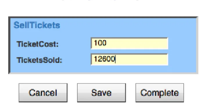
When the workitem is submitted, a PostItemConstraint event is generated for it by the Engine. There are no post-item constraint rules for this workitem, so again the event is just ignored. Then, a pre-item constraint notification is received for the next workitem (Sell Tickets). This workitem records the number of tickets sold, and the price of each ticket. Enter a price of $100 per ticket, and 12600 as the number of tickets sold, and then complete the workitem (Figure 3.6). Notice that the entered number of tickets sold (12600) is slightly more than 50% of the venue’s seating capac-ity (25000). The next workitem, Do Show, does have a pre-item constraint rule tree, and so when it becomes enabled, the rule tree is queried. The effective composite rule for Do Show pre-item tree (as viewed in the Rules Editor), is:
In other words, when Do Show is enabled and the value of the case data at-tribute “TicketsSold” is less than 75% of the seating capacity of the venue, we would like to suspend the workitem, run the compensatory worklet ChangeToMidVenue, and then, once the worklet has completed, continue (or unsuspend) the workitem. Follow-ing the logic of the ripple-down rule, if the tickets sold are also less than 50% of the capacity, then we want instead to suspend the workitem, run the ChangeToSmallV-enue worklet, and then unsuspend the workitem. Finally, if there has been less than 20% of the tickets sold, we want instead to suspend the entire case, run a worklet to cancel the show, and then remove (i.e. cancel) the case. In this example, the first rule’s condition evaluates to true, for a “Tickets Sold” value of 12600 and a seating capacity of 25000, so the child rule node on the true branch of the parent is tested. Since this child node’s condition evaluates to false for the case data, the rule evaluation is com-plete and the last true node returns its conclusion.
Figure 3.6 The Sell Tickets Workitem (from YAWL User Manual).
The result of all this can be seen in the Work Queues screen of the worklist. The Do Show workitem is marked as “Suspended” and thus is unable to be selected for starting, while the ChangeToMidVenue worklet has been launched and its first workitem, Cancel Stadium, is enabled and may be started. By viewing the log file, you will see that the ChangeToMidVenue worklet is being treated by the Exception Ser-vice as just another case, and so receives notifications from the Engine for pre-case and pre-item constraint events also. Start Cancel Stadium accepts the default values, and completes. Notice that the worklet has mapped the data attributes and values from the parent case. Next, start the Book Ent Centre workitem - by default, it contains the data values mapped from the parent case. Since we are moving the concert to a smaller venue, change the values to match those in Figure 3.7, then complete the workitem. The third workitem in the worklet, Tell Punters, is designed for the marketing depart-ment to advise fans and existing ticket holders of the change in venue. Start the workitem. Notice that the values here are read-only (since this item is meant to be a notification only, the person assigned does not need to change any values). This is the last workitem in the worklet, so when that is completed, the engine completes the case and notifies the Exception Service of the completion, at which time the service com-pletes the third and final part of the exception handling process, i.e. continuing or un-suspending the Do Show workitem so that the parent case can continue. Back at the Work Queues page, the Do Show workitem is now shown as enabled and thus is able to be started. Check it out now and notice that the data values entered in the worklet’s Book Ent Centre workitem have been mapped back to the parent case.
Figure 3.7 Effective Composite Rule for Do Shows Pre-Item Constraint Tree (from YAWL User Manual).
3.2 ProActive
ProActive (PA) is an open source middle-ware software presented as a Java li-brary, aiming to simplify the programming of multi-threaded, parallel and distributed applications for Grids, multi-core, clusters and data-centers. With a small set of primi-tives, ProActive provides an API allowing the development of parallel applications which can be deployed on distributed systems using the deployment framework. ProActive doesn't require any modification to Java or to the Java Virtual Machine, therefore allowing the deployment of applications using ProActive API on any operat-ing system that provides a compatible JVM. In the rest of this subsection we will con-centrate on the deployment framework with its two main components, PA Scheduler and PA Resource Manager.
3.2.1 ProActive Scheduler
Executing parallel tasks on distributed resources, requires a main system for managing resources and handling task executions, also known as a batch scheduler. The scheduler enables users to submit jobs, containing one or several tasks, and then to execute these tasks on available resources. The ProActive Scheduler is connected to the Resource Manager, thus providing resource abstraction. The Scheduler is accessi-ble either from a Java programming API or a command-line based job submitter. In ProActive Scheduler a job is the entity to be submitted to the scheduler, com-posed of one or more tasks. A task is the smallest schedulable entity, and will be exe-cuted in accordance to a scheduling policy on the available resources. There are two types of tasks:
✗ Java Task – its execution is defined by a Java class extending the
JavaExe-cutable class from the ProActive Scheduler API.
✗ Native Task – its execution can be any user program, a compiled C/C++ appli-cation, a shell or batch script; a native task can be specified by a simple mand line, or by a generation script that can dynamically generate the com-mand to be executed.
By default the Scheduler will schedule the registered jobs according to a FIFO policy, but if a job needs to be executed faster one must increase its priority or contact the Scheduler manager. A job can be created using an XML descriptor or the provided ProActive Scheduler Java API or also with a simple flat file. When creating a job, one can specify several parameters like: name, priority, cancelJobOnError,
restart-TaskOnError, nbMaxOfExecution, logFile, variables, genericInformation, JobClass-path, inputSpace (an URL representing an abstract (or real) link to a real data space), outputSpace. Similar to a job, a task can also have different parameters, some
of them being identical to those for a job. Some parameters specific to a task are:
Walltime (timeout), parameters (to be transferred to the executable), numberOfNodes, scripts, selectionScript, pre/post script (to be executed before and after the
executable), cleaning-script (executed after the executable or post-script).
The Scheduler infrastructure allows the user to handle files during the scheduling process, by specifying input and output data spaces. As there are default input/output spaces, users can also define their own data spaces by specifying them in the job de-scriptor. Once a job's execution ends, it is possible to obtain the result of the job.
3.2.2 ProActive Resource Manager
Nodes Sources is an entity in charge of nodes acquisition/release from particu-lar underlying infrastructures. It consists of two components: infrastructure manager and node source policy.
The infrastructure manager is responsible for communication with an infrastruc-ture, having three default implementations: Default Infrastructure Manager (used with the ProActive agent), GCM Infrastructure Manager (able to acquire/release nodes scribed in the GCM deployment descriptor), GCM Customized Infrastructure (can de-ploy/release a single node to/from the infrastructure).
Node source policy is a set of rules and conditions which describes when and how nodes have to be acquired or released. Policies use node source API to manage the node acquisition. There are 4 policies implemented which should cover the most common scenarios: static node source policy, time slot policy, “release when
sched-uler is idle” policy, “schedsched-uler loading” policy.
New infrastructure managers or node source policies can be integrated into the Resource Manager as plug-ins, like SSH Infrastructure (a basic but functional way to acquire resources through an SSH connection), PBS Infrastructure (acquires resources on an existing PBS installation). Beside this, the Resource Manager supports also the integration with the Amazon EC2, an Amazon Web Service that allows its users to use machines (instances) on demand on the cloud, but most important for us, the inte-gration with a virtualized infrastructure. Such an infrastructure runs a virtualized soft-ware and then can be used as a resource pool for Resource Manager (RM) execution. The way RM nodes belonging to a virtualized infrastructure are acquired is divided into three steps:
✗ Contact the virtual machine manager – for powering on the virtual machines
that will be used to run RM nodes.
✗ Start the RM nodes – this step requires the retrieval of the information
provid-ed in the previous step.
There are several types of virtualizing software that Resource Manager can han-dle, like VMWare products, XenServer or xVM Virtualbox. Each type of software needs a different configuration in order to communicate with the Resource Manager properly.
3.3 Grid 5000 Computing Infrastructure
Grid 5000 is a scientific instrument for the study of large scale parallel and dis-tributed systems. It aims at providing a highly reconfigurable, controllable and easy to monitor experimental platform to its users. 17 laboratories are involved in France with the objective of providing the community a testbed allowing experiments in all the software layers between the network protocols up to the applications. In addition to theory, simulators and emulators, there is a strong need for large scale testbeds where real life experimental conditions hold. The size of Grid 5000, in terms of number of sites and number of processors per site (9 sites, 1600 nodes, 23 clusters, 6200 coeurs), was established according to the scale of experiments and the number of researchers involved in the project. Since this platform is research dedicated and highly versatile in terms of applications accepted for deployment, we think that it is a good option to pass to a large scale our test platform.
Figure 3.8 Grid'5000 sites in France.
3.4 Test Cases
For testing purposes we use test-cases provided by an industry partner in the OMD2 project [12]. These are modeling and optimization applications with different levels of complexity and computation demands. The first two test cases concern a con-ditioning duct in 2D (Fig. 3.10) and 3D (Fig. 3.11) having an estimated computation time of 5min CPU and 30min CPU respectively. The third test case treats the model-ing and optimization of an engine cylinder with a considerably increased computation time of 100h CPU (Fig. 3.9). The last and most complex test case studies the aerody-namics resistance optimization of a van vehicle, with the estimated computation time of 1000h CPU (Fig. 3.12).
Figure 3.9 Input Valves. Figure 3.10 AirConditioningDuct2D.
Figure 3.11 AirConditioningDuct3D. Figure 3.12 Aerodynamics.
-150 -100 -50 0 50 100 150 200 250 300 50 100 150 200 250 300 350 Conduit d'admission P1 P2 P3 P4 P9 P10 P11 P12 P5 P6 P7 P8
4 Theory applied through Software Tools
In this section we present some practical achievements performed until now, using the software tools already described. Also, ideas for future implementations are presented. In this regard we focus on how the software tools can be extended to better answer the theoretical requirements, what other tools can be studied and used, and nevertheless how the theory can be refined in order to formulate a schema for a re-silience algorithm.
Since the final testbed must incorporate most of the tools described in the pre-vious section, the first concern was to find ways to interconnect those tools. We first started to analyze how task execution can be externalized from YAWL, knowing that the engine is only in charge of correctly scheduling and enabling the application tasks in cases and also managing the input/output data at task and net level, but not actually executing the tasks. For each and every atomic task scheduled by the engine for execu-tion, the responsibility of executing is transferred to a so-called YAWL Custom Service [37]. If a task is not associated at design time explicitly with a custom implemented service, one by default is assigned for its execution. Being part of the more general class of YAWL services, these custom services forming a delegated-execution frame-work is the extensibility cornerstone of the YAWL system.
4.1 Developing a Simple Custom Service
The first custom service developed was designed to simply execute a shell com-mand. Not so important for its functionality, the aim was to have a proof of concept of how the YAWL engine can be interconnected with a simple external application like Shell and what are the precise steps to follow. At the core of each Custom Service are the following Interface B classes available with a YAWL engine distribution:
✗ InterfaceB_EnvironmentBasedServer – a Java servlet responsible for receiv-ing event notification from the engine.
✗ InterfaceB_EnvironmentBasedClient – provides methods that allow a Custom Service to call specific end-points on the engine side.
✗ InterfaceBWebsideController – an abstract utility class that encapsulates much of the functionality of the other two classes, designed to be extended by the primary class of each Custom Service.
An overview of the various interfaces in the YAWL environment is shown in Figure 4.1. The first step is to create this primary class that has to extend InterfaceB-WebsideController. Beside a number of helper methods and data members that the service will inherit, InterfaceBWebsideController contains two abstract methods that all Custom Services must implement:
✗ public void handleEnabledWorkItemEvent (WorkItemRecord
workItem-Record) – it is called when the engine creates a new work item and places it in
the enabled state.
✗ public void handleCancelledWorkItemEvent (WorkItemRecord workItem-Record) – executed when an enabled or executing work item is cancelled by the engine.
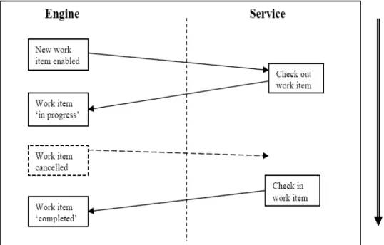
A Custom Service is responsible for every work item with which is associated, that is being checked out from the engine and in the end checked back in with the eventually updated data (Fig. 4.1). In between these two stages the developer of the Custom Service has full control. In our case this is where we make a call to the shell command with the program we want to execute. For simpler services, these two steps along with the service's functionality are completely encapsulated in the implementa-tion of the handleEnabledWorkItemEvent method. But before any of these acimplementa-tions is performed, a Custom Service must first establish a connection with the engine through two methods inherited from InterfaceBWebsideController: connect (String userID,
String password) – attempts to create a session with the engine by passing
authentica-tion credentials and returning a unique sessionHandle, checkConnecauthentica-tion (String
ses-sionHandle) – returns true if the current session handle is valid.
After the primary class is completed it will have to be bundled inside a Web Ap-plication file (war) and loaded into a servlet container (e.g. Apache Tomcat). The ba-sic structure of such a web archive looks like this:
✗ a root directory – containing all the html and jsp files used by the service ✗ a sub-directory of the root, called WEB-INF containing:
• a web.xml file – containing configuration information for the application • a sub-directory called classes – where any needed class file not present in
the jars is added (a good advise would be to include here the entire YAWL engine distribution, and eliminate afterward the unnecessary packages) • a lib sub-directory – where any jar libraries needed by the application are
to be included
Every Custom Service must include a web.xml file in its WEB-INF directory. The file contains the necessary deployment configuration values for the service. As an example, the Twitter Service's web.xml is shown in Listing 4.1 (APPENDIX A). Once registered, a Custom Service may receive XML messages from the Engine at endpoints identified by URLs derived from the base URL provided at registration. On the other hand, the Custom Service can send XML messages to the Engine at end-points identified by URLs that the Custom Service is assumed to know. A collection of Java classes included in the YAWL distribution provide several APIs
that can be used to implement the required endpoints without expecting any knowl-edge about the URL encoding and XML formatting used. Specifically, a Custom Ser-vice will use an API known collectively as Interface B to define the interactions in-volved in taking responsibility for and performing the execution of a task’s activities. Four basic interactions are particularly relevant at this stage (Figure 4.1):
Figure 4.1 Interface B Basic Interactions (YAWL Technical Manual).
4.2 Interconnecting YAWL and ProActive Scheduler
After achieving this first interconnection between the YAWL engine and a shell program, the next step is to interpose in between the ProActive Scheduler. The princi-ple of developing a Custom Service remains the same. However in the primary class, extending the InterfaceBWebsideController, the developer must replace the method in charge with the actual functionality, with the creation of all the entities necessary for a job submission. In consequence, one must obtain a scheduler interface by connecting to a running PA Scheduler. Then a job and its corresponding task have to be created. Beside this, a class extending the JavaExecutable must be defined, where all the ser-vice's functionality will be inserted (execution of a shell script in our case). This exe-cutable class will be added afterward to a JavaTask object (part of a Job object) de-scribing the task to be executed by the service. In the end the job can be submitted to the scheduler using the previously obtained interface, and the results can be extracted after execution (Fig. 4.2).
Figure 4.2 YAWL and ProActive Interconnection Scheme.
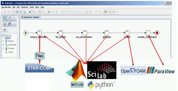
Applying the concepts of interconnection described earlier, we have deployed and executed the first two test-cases from the OMD2 project. In Figure 4.3 there is the workflow decomposition of the second case. Since the execution time of this test-case is in the order of minutes, it has only the value of a proof of concept for executing scientific applications designed in YAWL through YAWL Custom Services and ProActive. The test-case script is split into atomic execution units that are afterward associated with a YAWL task. Each execution unit is actually represented by a shell script that is performing a specific task from the global test-case. The call of such an execution unit script will be wrapped in a ProActive Task and at its turn in a ProActive
Job. The Custom Service is responsible for contacting the ProActive Scheduler,
build-ing the ProActive Job and launchbuild-ing it through the default ProActive resource
Manag-er. A set of parameters are specified for each YAWL task in order to indicate to the
Custom Service some useful information like:
✗ command – the name of the script file to be invoked
✗ dir – the directory in which the script files are located on the executing system ✗ result – a variable that will store the result of the execution (usually a message
The YAWL Custom Service will map these parameters, will execute the com-mand in the specified directory and will return a status message as a result. The result of the experiment can be seen in Figure 4.4, created using the paraview tool from OpenFoam that is invoked in the 6thtask of the YAWL workflow.
Figure 4.3 YAWL workflow for test-case nr.2 from OMD2 project.
4.3 Deploying Computing Nodes on a Virtualized Infrastructure
Another domain of special interest is in resource managing and more specifically in the Virtualized Infrastructure of the PA Resource Manager. First of all, benefiting from an infrastructure based on virtual machines allows rapid deployment tests with-out being necessary to have a real distributed platform available. Even more, when we'll be ready to deploy our workflow platform on Grid 5000 for example, it will be a lot easier to deploy virtual machines on the resources, with already installed services, thus avoiding the installation of software tools directly on the nodes. We will skip the pure technical details of the process and instead we will only expose the major steps to follow in order to use such an infrastructure. Until now we used the GUI (Fig. 4.5) provided by ProActive, for Resource Manager configuration and VirtualBox (VB) for the virtual machine (VM) software [40].
✗ Install and prepare VirtualBox – this step includes the installation of the VB
software, its configuration and the creation of a virtual machine on the re-sources we want to use for execution.
✗ Register a new service on the newly created virtual machine – in this step an
already created script for node creation and registration must be registered as a service on the new VM so that it starts automatically when the machine is turned on.
✗ Prepare the host environment – refers to a set of servers that must be started
on the host environment (VB server, message router, rm script) and also a set of configuration information that must be provided to these servers in order to correctly deploy the virtual nodes.
Figure 4.5 Virtual Infrastructure NodeSource Creation Dialog (from Resource Manager Documentation)
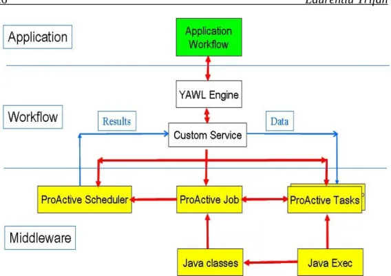
In Figure 4.6 is presented a global schema of the path followed by a task for execution. The YAWL engine checks out the task to a custom service. An instance of a ProActive Scheduler is obtained that invokes a dedicated ProActive Resource Man-ager. This Resource Manager has already deployed a Virtualized Infrastructure that is being used for executing jobs coming from the scheduler. Using this Virtualized Infra-structure, our goal is to build the foundation of the distributed aspects of the collabora-tive platform.
Figure 4.6 Global Schema of a Collaborative Platform using a Virtualized Infrastructure.
4.4 Towards a Resilience Algorithm
Until now we have talked only about features that are used for interconnecting the software tools with the purpose of forming a collaborative platform. In the follow-ing we focus on how exactly aspects of resilience can be practically addressed with the available tools. The final goal is to sketch a schema of a resilience strategy that with time will evolve in a precise algorithm.
4.4.1 Checkpoint – strategy and implementation
No matter how the final resilience algorithm will look like, checkpointing will play an important role in its definition. A lot of studies have been performed on imple-menting efficient checkpoint/recovery algorithms [25, 26, 27, 28, 29, 31, 32, 33, 35]. For the theoretical basis we will take as a starting point the Asymmetric cascading
checkpoints [1] strategy with the heuristic rules defined by the user. This means that
according to his knowledge about the critical parts of his application, a user can speci-fy at design time which tasks are critical and should be checkpointed or, on the con-trary, which one can be skipped. If the nature of the application allows, he can also specify some automatic rules like: no output backup for join operations, only one out-put backup for fork operations, etc. For the practical implementation, one idea would be to use the available functionality provided by YAWL. A new function has been cre-ated in YAWL to extract the current state information for a running specification us-ing the InterfaceB. The followus-ing information can be obtained through such a process:
✗ All the running cases of a given specification and their marking
✗ All the data values associated with each case
✗ Information about enabled work items
✗ Information about executing work items and the resources in use
4.4.2 Failure Prediction
Since in the near future scientific applications will reach the level of exascale in terms of needed resources, the basic checkpoint/recovery procedure will be insuffi-cient, as already stated in the Theoretical Study section. A failure prediction mecha-nism is almost indispensable to provide the necessary level of resilience for such com-plex applications. From the literature [4] we find out that these predictive methods are mostly based on data and process mining. A good starting point in this direction is the analysis of the ProM software tool [8, Process Mining and Simulation, ch.17], which is a framework for process mining. Even if from the characteristics presented in the manual seems not the perfect tool for run-time failure prediction, studying its func-tionality will be helpful in terms of data extraction from YAWL, data analysis, and process behavior prediction. The basic idea behind ProM is to create a process simula-tion model that accurately reflects the real process, using three types of data sources extracted from YAWL:
✗ Design information – a YAWL file containing the static design information
for a particular process model, including the control and data flow, initial data values, and resource assignment strategies.
✗ Historical information – an MXML log file providing historical information
about a process in the form of event logs.
✗ State information – current state file providing data values, timestamps and
re-source information for currently running cases of a given specification.
By merging the above three sources of information into a simulation model, it is possible to construct an accurate model based on observed behavior rather than a man-ually constructed model. Moreover, the current state information supports a “fast for-ward” capability, in which simulation can be used to explore different scenarios with respect to their effect in the near future.
Using failure prediction methods can be useful in deciding when and where
to place a checkpoint during the execution of an application. In this way we can improve the heuristic strategy of checkpointing the application, which is mostly static, by using also run-time decisions, more accurate for the current running case. Using the same concepts as ProM, a run-time failure prediction strategy is to
de-velop some meta-learning procedures for failure patterns. This way, when a failure oc-curs, the system will capture the context of the application (data values, previously ex-ecuted tasks, type of failure, failure recovery technique). The information gathered
in this way will be used later on during execution to recognize patterns of failure by comparing the current context with previous failure contexts, and decide whether enough symptoms exist to predict a failure in the near future. If the
an-swer is affirmative, preventive measures can be taken to avoid the failure (e.g. chang-ing a parameter value, or switchchang-ing to a different resource or some kind of user
interaction and if this is not possible, a checkpoint can be placed so that the recovery process becomes faster.
4.4.3 Resilience through Exception Handling
The exception service implemented in YAWL can be an important tool in the study of workflow resilience (section 2.3). It can provide means for failure detection, using the many types of exceptions (failures) that is able to recognize and it can also contribute to the failure-pattern learning procedure using the handling techniques and compensation processes provided by the service. Exceptions can be triggered both when the actual failure occurs, applying a recovery process predefined or dynamically conceived, but it can also alert the system when a failure pattern matches the current context, applying the associated preventive handling technique. The exception service can also be used for triggering the static checkpoints designated by the user at design time. Therefore by checking a data constraint, the workflow system can identify if it's the case to execute a checkpoint of the application.
4.4.4 Raw Algorithm Schema
After having presented all these research directions for workflow resilience, we define a raw schema of a resilience algorithm that with time must get refined towards a well specified algorithm ready for implementation and testing. The schema can be divided in two major parts: design-time and run-time. Here are the basic steps that we propose:
1. The user defines portions of the application (individual tasks or set of tasks) that need special attention. Let's call them checking points or adaptation points.
2. A set of a priori known failures (or exceptions) are defined through RDR rules, with an associated handling technique.
3. The user can also specify at design-time parameters that can be dynamically adapted for failure avoidance (considered non-critical parameters) or tasks that can be skipped (non-critical tasks) for the same reason (considered error prone).
4. According to the specifications made at design-time, during execution the sys-tem will check at every adaptation point the failure possibility (using a predic-tive algorithm to be defined) and decide whether:
1. continue execution
2. try to adapt the context and continue execution 3. perform a checkpoint and continue execution 4. migrate execution flow to a different resource
5. backtrack to a previous checkpoint and ask for corrective action from the user
5. Whenever a known or unknown failure occurs, learn the context in which it has occurred and register the exception type and other meta-data. If a recovery technique exists, apply it, if not define one (automatically or manually). The registered context data will be used later on in the predic-tion algorithm.
5 Conclusions
Workflow systems will play an important role in managing large scale comput-ing infrastructures for scientific applications. But the continuously growcomput-ing trend in number of computing nodes, combined with the increasing complexity of scientific applications renders these systems extremely exposed to failures, regardless the nature of the failure. This requires the concept of resiliency, meaning that the system should be able to detect the failure and dynamically recover so that the execution is per-formed in a safe manner. It requires also that the system supports a dynamic behavior when executing the application. Taking this into account, we showed that YAWL workflow system with its two services, Selection and Exception Services, is the appro-priate choice. The decision was also influenced by the YAWL's service oriented archi-tecture. With the possibility to develop Custom Services, the interaction with external applications becomes a lot easier. This is illustrated through the Custom Service de-veloped to realize the interactions between YAWL and ProActive for a set of shell scripts executions running an industrial test case. The outcome will be to implement a collaborative platform incorporating all the levels involved: scientific applications, workflow enactment system, middleware software, distributed computational infra-structure and users.
The proposed research directions for implementing resiliency in such a platform are the following:
✗ Efficient Checkpoint/Recovery algorithm using heuristic rules. ✗ Exception handling techniques as a way to detect and treat failures.
✗ Failure prediction using failure patterns constructed from historical data and current state.
✗ Combining the above mentioned strategy for an enhanced resiliency of the system.
The provided test cases from Renault assure the necessary complexity to accu-rately test the platform and its resiliency algorithm. Grid'5000 computational HPC in-frastructure provides the required level for large scale test-cases.
6 Acknowledgments
This study is supported by the French Agence Nationale de la Recherche (ANR) for the OMD2 project (Distributed Multi-Discipline Optimization) grant ANR08-COSI-007.
7 Bibliography
[1] Toan Nguyen, Laurentiu Trifan , Jean-Antoine Désidéri. “Resilient Workflows for Compu-tational Mechanics Platforms”. WCCM/APCOM, Sydney, July 2010.
[2] Manuel Caeiro-Rodriguez, Thierry Priol and Zsolt Németh. “Dynamicity in Scientific Workflows”. CoreGRID Technical Report, 31 August 2008.
[3] Jia Yu and Rajkumar Buyya. “A Taxonomy of Workflow Management Systems for Grid Computing”. GRIDS Laboratory Department of Computer Science and Software Engineering, University of Melbourne, Australia. ACM SIGMOD Record, 2005.
[4] Zhiling Lan and Yawei Li. “Adaptive Fault Management of Parallel Applications for High-Performance Computing”. IEEE TRANSACTIONS ON COMPUTERS, VOL.57, NO.12, DE-CEMBER 2008.
[5] Gopi Kandaswamy, Anirban Mandal and Daniel A. Reed. “Fault Tolerance and Recovery of Scientific Workflows on Computational Grids”. Eighth IEEE International Symposium on Cluster Computing and the Grid, 2008.
[6] International EXASCALE Software Project. ROADMAP 1.0. http://www.exascale.org/me-diawiki/images/a/a1/Iesp-roadmap-draft-0.93-complete.pdf.
[7] Zong Wei Luo. “Checkpointing for Workflow Recovery”. Large Scale Distributed Informa-tion System Lab, The University of Georgia, Athens, GA 30602.
[8] Arthur H.M. Ter Hofstede, Wil M. P. van der Aalst, Michael Adams, Nick Russell. “Mod-ern Business Process Automation: YAWL and its Support Environment”. Springer 2010. [9] The OASIS Research Team and ActiveEon Company. “ProActive Scheduling” - Manual. INRIA, Université Nice, CNRS, 2010.
[10] The OASIS Research Team and ActiveEon Company. “ProActive Resource Manager” - Manual. INRIA, Université Nice, CNRS.
[11] Jiexing Gu, Zimming Zheng, Zhiling Lan, John White, Eva Hocks, Byung-Hoon Park. “Dynamic Meta-Learning for Failure Prediction in Large-Scale Systems: A Case Study”.