HAL Id: cea-02479171
https://hal-cea.archives-ouvertes.fr/cea-02479171
Submitted on 14 Feb 2020
HAL is a multi-disciplinary open access
archive for the deposit and dissemination of
sci-entific research documents, whether they are
pub-lished or not. The documents may come from
teaching and research institutions in France or
abroad, or from public or private research centers.
L’archive ouverte pluridisciplinaire HAL, est
destinée au dépôt et à la diffusion de documents
scientifiques de niveau recherche, publiés ou non,
émanant des établissements d’enseignement et de
recherche français ou étrangers, des laboratoires
publics ou privés.
ICRH coupling optimization and impurity behavior in
EAST and WEST
G. Urbanczyk, L. Colas, X. Zhang, W. Helou, Y. Zhao, J. Hillairet, X. Gong,
E. Lerche, G. Lombard, Q. Ming, et al.
To cite this version:
G. Urbanczyk, L. Colas, X. Zhang, W. Helou, Y. Zhao, et al.. ICRH coupling optimization and
impurity behavior in EAST and WEST. 23rd topical conference on radiofrequency power in plasmas,
May 2020, Hefei, China. �cea-02479171�
ICRH coupling optimization and impurity behavior in
EAST and WEST
G. Urbanczyk
1, 2, L. Colas
1, X.J. Zhang
2, W. Helou
1, Y.P. Zhao
2, J. Hillairet
1, X.
Z. Gong
2, E. Lerche
3, 4, G. Lombard
1, Q.C. Ming
2, M. Goniche
1, Z. Ling
2, P.
Mollard
1, V. Bobkov
5, X.D. Yang
2, O. Meyer
1, L.N. Lu
2, J. Gunn
1, C. Yan
2, C.
Desgranges
1, J.M. Bernard
1, T. Zhang
2, F. Clairet
1, B. Pégourié
1, R. Dumont
1, W.
Tierens
5, D. Van Eester
3, F. Durodié
3, J.G. Li
2, EAST and WEST Teams
1 CEA, IRFM, F-13108 Saint Paul-Lez-Durance, France.
2 Institute of Plasma Physics, Chinese Academy of Sciences, Hefei 230031, People’s Republic of China 3
LPP-ERM/KMS, TEC partner, Brussels, Belgium
4 CCFE, Culham Science Centre, Abingdon, Oxfordshire OX14 3DB, UK 5 Max-Planck-Institut für Plasmaphysik, Boltzmannstr. 2, 85748 Garching, Germany
Abstract. This study compares experimental observations on the two challenges of Ion Cyclotron Resonance Heating
(ICRH), namely the coupling of waves to the plasma and the enhanced plasma surface interactions in EAST and WEST medium size tokamaks.
In WEST, Lower Hybrid (LH) power helps improving ICRH coupling. In both machines experiments reveal that fueling from the midplane not only helps to couple waves from nearby antennas like in other devices, but also has an impact on the scrape-off layer (SOL) density in regions that are not magnetically connected to the valves. Localized midplane nozzle valves allow similar (in WEST) or better (in EAST) coupling compared to poloidally distributed valves. Core density control requirements for long-pulse operation, in particular in L-mode regime, however limit the amount of gas that can be injected.
During ICRH impurities can contaminate the plasma to a level detrimental for the operation, e.g. 100% of ICRH power radiated on WEST. In WEST, tungsten (W) production measured by visible spectroscopy increases on all the observed objects during ICRH compared to a reference phase without ICRH. On some components (antenna side limiters, baffle, divertor) the rise is larger than with a similar LH power. The relative contribution of each object and physical process (RF-sheaths, fast ion ripple losses) to core contamination yet remains poorly known. Comparing antenna limiters with W-coating vs low-Z materials would help quantifying the role of these components. In EAST, the core W content, measured by EUV spectroscopy in presence of divertor sources only, is correlated with the total injected power, either from ICRH or LH. Since 2018 the LH guard limiter tiles were W-coated. Their contribution to the core W content appears more important than divertor sources, when the magnetically connected ICRH antenna is powered. Two-strap ICRH antennas magnetically connected to W components at the midplane already compromise high performance operations.
1. INTRODUCTION
Ion Cyclotron Resonance Heating (ICRH) is used in both the Experimental Advanced (EAST) (Fig. 1a) [1] and the full tungsten (W) Environment (WEST) Superconducting Tokamaks (Fig. 1b) to heat H minority in Deuterium plasmas [2]. H minority scheme can allow thermal ions to absorb up to half of the injected power. ICRH systems have been able to couple about 1MW per antenna, with indications of wave absorption. Meanwhile, ICRH heating can prevent heavy impurity accumulation similarly to broad ECRH [3]. In order to benefit from ICRH in the core, waves must be coupled to the plasma from antennas whose location at the edge is subject to a trade-off between (1) efficient coupling and (2) impurity generation which will be successively discussed in this paper.
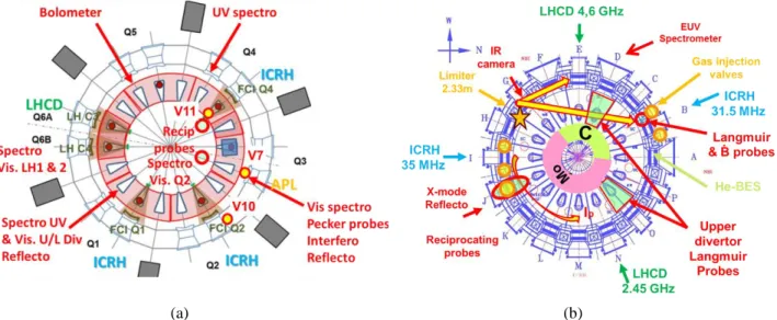
(a) (b)
FIGURE 1. WEST (a) and EAST (b) top view with diagnostics of interest for the study, LH and ICRH antennas, and fueling
valves in each device with top (V11 in WEST) poloidally distributed (V10 in WEST, I and B port in EAST) and nozzle valves at midplane (V7 in WEST and J-port in EAST)
All experiments presented were performed in L-mode combining Lower Hybrid Current Drive (LHCD) from two launchers and ICRH from two antennas. Stable loading however remains difficult in both machines. This is certainly due to a general lack of time for properly commissioning antennas before increasing gradually the power, but also because of the inherent complexity of physical processes specific to ICRF waves, such as mutual coupling, or the excitation of the so-called Radiofrequency (RF) sheath. Poor coupling, leads to the excitation of sheath potential, which results in electric fields, which can induce ExB density convections, and therefore locally modify the coupling efficiency … Solving coupling issues can then require to think of all phenomena self-consistently [4]. In addition to JET [5] and ASDEX Upgrade [6] results in H-mode, we will show how local gas injection can be used and combined with LH power to improve ICRF waves coupling in EAST and WEST L-mode discharges. In EAST and WEST, coupling at constant heating power was compared for several similar quantities of gas injected from different valves (Fig. 1).
The second challenge of ICRH is to apply a maximum of power by keeping low the levels of impurity (in particular high-Z) and radiation. ICRH-induced Plasma Surface Interactions (PSI) can be attributed to near or/and far field effects, both of them relying on RF sheath excitation. Near field effects refer to PSI in regions either close or magnetically connected to ICRF antennas around which slow waves can directly excite RF sheaths whereas we will talk of far field elsewhere. We will therefore start presenting far field-induced PSI on the high field side of EAST, and on the divertor of WEST. EAST divertor will then be discussed more specifically. Finally near field effects will be addressed exploiting different diagnostics in each device.
2. COUPLING OPTIMIZATION
WITH LOCAL GAS INJECTION AND LOWER HYBRID POWER
ICRF waves coupling basically define the efficiency by which power can be launched in the plasma (Rc = 2 Ptrans
Z0²/V max² [7]). If the coupling is very poor, large RF currents or voltage arise in the antenna preventing launching
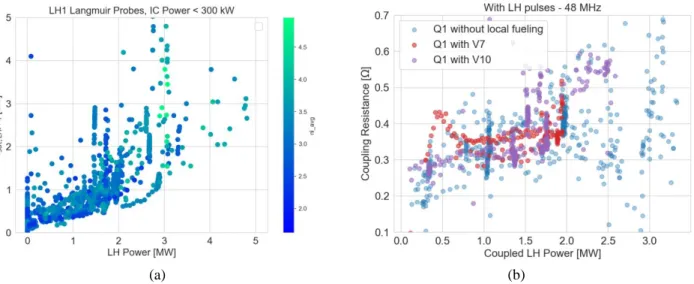
high RF power. Note all the power going into the plasma is not necessarily absorbed, such that it is important not to confuse wave coupling with wave’s absorption that will be discussed in the next section. In order to propagate, ICRF fast waves need a minimal density that is often higher than these in front of the antennas. Waves must therefore tunnel through an evanescence layer, and the aim of this section is to explain how this layer can be shortened. The first way to do it is to put the antenna closer to the plasma, but this is limited by heat loads and impurity issues. The second most efficient way is to increase the plasma density but this is in practice limited by Greenwald’s value over which plasma can disrupt. The third most efficient way is to increase wave frequency [8], but this is in practice also dictated by the scenario. We also found that increasing the LH power can help increasing density in the SOL more than in the core Fig.2a and therefore the coupling efficiency of ICRF antennas. It is known that as more power is injected, more goes in the SOL and contributes to ionizing neutrals and increasing electrons
(a) (b)
FIGURE 2. (a) Ratio of ion saturation current measured by Langmuir probes fixed on LH launchers corners (proxy of SOL
density) over the linearly integrated density from interferometry (proxy of core density) and (b) Q1 ICRF antenna loading plotted against LH power for WEST C3b campaign shots and different valves (Fig. 1a).
density [9], however we do not yet know precisely the mechanism by which LH in particular can help increasing density at the edge.
Finally, another way to improve ICRF loading is to fuel the plasma using valves at proximity of ICRF antennas. In JET [5] and ASDEX Upgrade [6], best coupling improvements at given gas rate were obtained by injecting gas at the midplane nearby ICRF antennas and the effect was relatively local toroidally (Table 1). In EAST, injections at the midplane is also the best solution (J-port in Fig. 1b), but unlike in JET and ASDEX, it did not only have an impact on the toroidally nearby antenna (I-port) but also on the other antenna (B-port) that is at the very opposite of the torus, far and not magnetically connected to the valve. Therefore in EAST, local gas injection at the midplane seems to have a global effect. This is not clearly understood yet, but several hypotheses are possible such as the weak pitch angle (long connection length), or maybe the position of LH launchers ~90° toroidally away from each ICRF antenna [7] where large amount of neutral gas could be ionized when passing in front of each launcher.
Parameters
JET
ASDEX-U
EAST
WEST
f ICRH [MHz]
42
30 - 36,5
34 - 35
55 - 57
k|| [m
-1] (π phas)
6,6
8
14
9
n
e,cut-off[10
18m
-3]
2
5 -- 4
9 -- 6
9
Cut-Off position
SOL
SOL
SOL
Confined reg°
B
T[T] / I
p[MA]
2,7 / 2,5
2 /0.8 - 2.5 /0.8
2,5 / 0,5
3,7 / 0,5
P
additionnalNBI
NBI
LH
LH
Confinement
H - mode
H - mode
L - mode
L - mode
Local Gas flow [e/s]
0,5 - 2 x 10
220,5 - 1 x 10
228 - 11 x 10
201 - 8 x 10
20Best Solution
Midplane
Midplane
Midplane
-
Effect
Local
Local
Global
-
TABLE 1. Tokamaks and ICRF heating system parameters
In WEST so far, no significant improvement was observed with local injection compared to other injection (top). This can be explained by the facts that unlike in others devices, not only very tiny quantities of gas were injected, but the ICRF wave cut-off layer is not in the SOL but in the confined region. It is therefore understandable that small quantities of gas did not have much influence on the cut-off position. Another important point is that valves located at the midplane are only a good solution if they are radially retracted enough to let neutral gas diffuse before being ionized (~20cm behind antenna limiters), like in ASDEX, JET or EAST. Putting the valves too close from the plasma, like valves distributed poloidally along EAST antennas limiters or midplane nozzle valve on WEST
Antennas Protection Limiter (APL) can behave like a source of impurity. Gas injected directly in a region of relatively high Te does not have time to spread and is prematurely ionized, inducing large density increase locally, sometimes impurity sources or/and antenna arcing.
3. ICRH-RELATED IMPURITY SOURCES
ICRF plane waves can propagate under two eigenmodes with substantially different properties; the Slow Wave (SW) with non-negligible electric field component parallel to magnetic field and the Fast Wave (FW) which electric field component is perpendicular to magnetic field. SW parallel electric field is known [7, 11, 12, 13, 19] for exciting RF sheath on PFCs and induce deleterious PSI effects. In most tokamaks SOL plasma, the SW is evanescent such that it cannot propagate far from where it is excited. We will therefore refer to PSI observations related to direct excitation of the SW as near field effects. The FW must propagate up to the ion cyclotron resonance layer and heat core plasma. However, in scenarios with poor sinle-pass absorption, non-negligible amount of power be carried by FW up to PFCs far away from the antenna. As FW reflects on PFCs (actually an evanescent FW transmitted beyond a cut-off layer reflects on a PFC) part of the power is converted into SW and RF sheath are excited. We will then refer to PSI observation resulting from this type of mechanism as far field effects. We first discuss far-field effects on EAST high field side wall and WEST divertor target. Then we will present observations made on EAST divertor, mostly attributed to near field effects. Finally we will show examples of near field impacts on low field side PFCs either close or magnetically connected to active ICRF antennas. Details on the effects influence on WEST operation are further discussed under [10], while a very complete overview of this topic can be found under [11] and reference therein. Note experimental approaches are substantially different in both tokamaks; WEST has a full tungsten environment [2] but is equipped of many visible spectroscopy lines of sight [12] allowing relative comparison of impurity sources, whereas multiplicity of materials in EAST can be used to extract relatively local information on PSI with Extreme Ultraviolet (EUV) spectroscopy [13]. So far, WEST visible spectroscopy data were not absolutely calibrated such that relevant information can already be extracted from qualitative variations but quantitative comparison of different sources was not yet possible. We also acknowledge that EUV spectroscopy is not the most appropriate diagnostic for impurity sources study, but since temperature and density profiles did not significantly change along EAST experiments, temperature effects on impurities brightness and transport are assumed negligible.
3.1 FAR FIELD EFFECTS
In order to observe effects of the so called “far field”, one must be sure that there is almost no possible magnetic connection to an active ICRF antenna, which can be pretty restrictive in tokamaks like EAST and WEST having two ICRF antennas occupying two different toroidal positions and with relatively low pitch angle (cf BT/Ip in Table 1). In
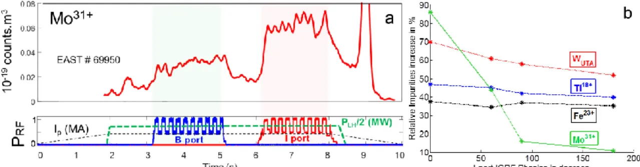
addition, far field can be hard to observe in devices with high single pass absorption like ASDEX Upgrade [14] while they tend to play a bigger role in smaller devices like Alcator C-Mod [15]. In the H minority heating scheme, ICRF wave absorption efficiency changes with the isotopic ratio. In EAST, the hydrogen concentration is often too high due to strong materials outgassing, and it can get lower with the help of daily lithium coating. On the contrary, before 2019 in WEST, the hydrogen concentration was often too low, since all materials were relatively new and that almost no hydrogen was injected due to the fact that piezo valves are not designed to inject tiny quantities. In both EAST and WEST, far field effects were therefore observed in scenarios with relatively poor absorption efficiencies. Unlike most metal species in EAST, a correlation was found between the Molybdenum (Mo31+) line intensity measured by EUV spectroscopy and the I-port antenna phasing (Fig. 3b). Since Mo is very unlikely to come from the low field side walls – not only because the density is too low to allow significant PSI but also because it should have also react when powering the B-port ICRF antenna – Mo was suspected to come from the high field side wall facing I-port (Fig. 1b). Lacking of appropriate diagnostic for measuring any relevant quantity at the high field side wall, modelling with TOMCAT [16] and EVE [17] codes were made to test this assumption. As the phasing goes from dipole (180°) to monopole (0°), modelling not only predict a degradation of the single-pass absorption from 55 down to 15%, but also an increase of the parallel component of the electric field at the high field side (Fig. 4). These results are then consistent with a far field-induced Mo source located at the high field side wall facing I-port.
FIGURE 3. (a) Time traces of Mo31+ brightness (EUV spectroscopy) by successively powering each ICRF antenna of EAST (b) Different metal species brightness evolution along I-port antenna phasing scan.
(a) (b)
FIGURE 4. Real and imaginary parts of the parallel component of the electric field computed with TOMCAT code [16] for
(a) dipole (180°) and (b) monopole (0°) phasing of the I-port ICRF antenna in EAST
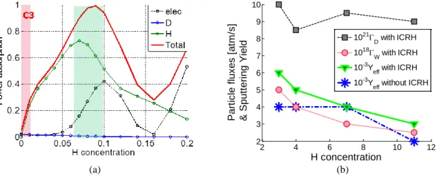
In WEST, simulations with TOMCAT [16] predict that a hydrogen concentration of 7% is optimal for ICRF wave absorption (as shown by the green region in Fig. 5a). However the H concentration was in practice very hard to control and was often too low during C3 campaign (as shown by the red region in Fig. 5a). It was still possible once to explore different H concentration in discharges only heated with ICRH, and observations made on the inner divertor target with visible spectroscopy are represented in Fig. 5b. Each point is the result of several Lines Of Sight (LOS) averages on a time interval of interest. D and W atom fluxes are estimated from calibrated brightness of DIδ
and WI respectively pondered by S/XB coefficients taken for SOL temperatures of about 20eV measured by divertor Langmuir probes (ex : ГD ≈ DIδ x S/XBDIδ). ГW / ГD is interpreted as a proxy of the effective sputtering yield.
As the H concentration increases, we see that it does not have much impact on sputtering in ohmic case as seen on the blue series. However in presence of ICRH, we see that both the sputtering and the tungsten outflux decrease as if ICRF absorption improves consistently with H concentration, and less power reaches the divertor target and excites RF sheath. This is another example of far field excitation on WEST divertor. Note far field effects could for instance be totally suppressed if 100% single pass absorption can be fulfilled, which rarely happens, but is expected to improve as the size of the device increases
In EAST though, even if the absorption is not optimal such that far field certainly somehow has some impact in the divertor region, most observations are correlated with magnetic connections to active antenna and therefore attributed to near field effects [18, 19].
(a) (b)
FIGURE 5. Evolution along H concentration scan of (a) the ICRF power absorption efficiency computed with TOMCAT code
and (b) the deuterium and tungsten atom fluxes on inner divertor target measured by visible spectroscopy; the ratio of tungsten over deuterium fluxes is used as a proxy of the effective sputtering yield and plotted with and without ICRH in WEST.
3.2 NEAR FIELD EFFECTS
In EAST divertor, RF modification of the floating potential is recorded by Langmuir probes magnetically connected to active antenna. It has typically been observed that the magnetic field lines passing in front of active ICRF antennas are negatively biased while those connected to surfaces behind limiter leading edge are positively biased [18]. Despite these observations holding in both upper and lower single null configurations, these potential rectification do not seem deleterious in terms of PSI. On the contrary, based on observation of the W continuum, it has been shown that PSIs in the divertor region are the result of the total injected power rather than ICRH [19]. Species either close (Fe from antennas Faraday screens) or with strong magnetic connection to active ICRF antenna (Ti plates) however show better correlation with ICRH settings, which is the results of near field effects on antenna surrounding.
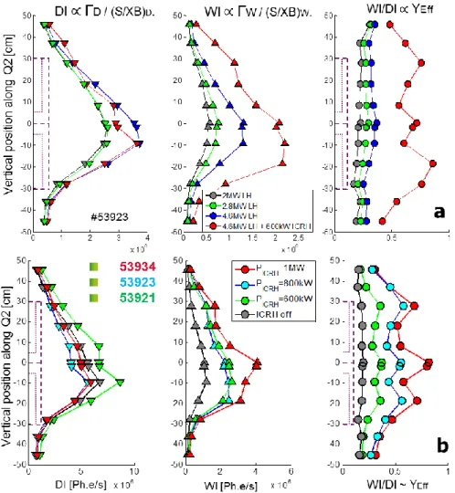
In WEST, poloidal profiles of DI, WI intensities and their ratio are plotted along Q2 ICRF antenna limiter height in Fig. 6. DI, WI and their ratio are respectively interpreted as a proxy of the neutral tungsten outflow, the deuterium ions influx, and effective sputtering yield. As shown in Fig. 6a by grey, green and blue profiles, while deuterium flux increases a little with LH, tungsten outflow increases more, resulting in a linear increase of the sputtering yield along the whole limiter. The red series shows the deleterious influence of ICRH on the tungsten outflow, likely due to RF sheath non-linear excitation leading to sputtering yield increase preferentially on antenna corners and center. Note that for the same amount of power coupled, Yeff increases much more with ICRH than with LH.
Fig. 6b shows that near field effects only get worse as ICRH power increases up to 1MW. Similar increase is observed on other magnetically connected objects (to a smaller extent as connection length increases), like the APL which could also constitute an important impurity source. Absolute calibration and dedicated experiments allowing comparisons with UV spectroscopy will yet be necessary to conclude on each source contribution to core contamination. 2 4 6 8 10 12 2 3 4 5 6 7 8 9 10 Part ic le flux es [ at m /s ] & Sput tering Yield H concentration 1021D with ICRH 1018W with ICRH 10-3Y
eff with ICRH
10-3Y
FIGURE 6. Poloidal profiles of DI, WI intensities and their ratio are plotted along Q2 ICRF antenna limiter height
for different LH (a) and ICRH (b) power in WEST
Before 2018, W was only in the upper divertor region of EAST. At that time the intensity of the W continuum was 8 times larger in an Upper Single Null (USN) than in a similar Lower Single Null (LSN) ohmic discharge. In 2018, LH limiters in EAST were changed from carbon to tungsten, then only 3 times more W was found in USN than in LSN discharges. From this USN/LSN comparison with and without W sources at the midplane, and using simple assumptions, one can estimate that in ohmic discharges, LH limiters already contribute to 25% of the core W contamination [20]. This ratio will likely increase significantly as the ICRF antenna magnetically connected to the W limiters is powered.
In discharges heated with ICRH, no quantitative estimation was possible yet, but we can already tell that the B-port antenna magnetically connected to LH limiters plays a dramatic role; W content is for instance multiplied by 6 as 3.5MW from NBI are replaced by 300kW from ICRH B-port (magnetically connected) and by 10 if the ICRH power is increased up to 750kW. As a consequence and because ICRF settings cannot be much further optimized with only two toroidal straps, B-port antenna is presently incompatible with high power long discharges. These observations advice against having 2-strap ICRF antenna with passive limiters magnetically connected to high-Z impurity sources at the midplane.
CONCLUSION AND PROSPECTS
Beyond putting antenna closer to the plasma, increasing plasma density and waves frequency, increasing the LH power and injecting gas locally from valves located as close as possible to the midplane and radially retracted behind antenna limiter can help. The role of LH is not yet clearly understood but will be subject to further investigation in future experiments. Advantages of single nozzle over poloidally distributed valves were observed in
EAST but not in WEST. These tools to optimize ICRF coupling are however often subject to limitations and trade off with impurity production.
To study ICRH-related impurity sources, biggest difficulty consist in disentangling near from far field effects and quantify their respective contribution to plasma contamination. Far field effects were observed both in EAST high field side wall and WEST inner divertor target. These effects correlate with poor ICRF wave absorption efficiency and could therefore be mitigated by achieving for instance better control of the H concentration in WEST, and exciting spectrum with higher k|| in EAST. Note the higher k||, the better the absorption, but the worse the coupling. Therefore mitigating far field effects can somehow also be constrained by coupling issues and trade-off with near field effects. Near field effects can be seen in regions magnetically connected to active ICRF antenna. In some cases, near field effects has not deleterious influence on plasma surface interactions like in EAST divertor. However in most cases and in particular on limiters, near fields lead to significant increase of potentials, ions effective sputtering yield, and impurity production. It is still very challenging to quantify each source contribution to core contamination, especially in WEST which is a full tungsten environment. In EAST though, situations with and without tungsten sources at the midplane can be compared. The result is that building antennas with only two toroidal straps and passive limiters magnetically connected to W located at the midplane should be avoided. Considering limited lifetime of low-Z materials coating, and operational constrains in future devices like ITER or CFETR, more speculative solutions can be explored to simultaneously allow good coupling and little impurity production such as active limiters or travelling wave antennas [21].
ACKNOWLEDGMENTS
The whole EAST ICRH team, colleagues in charge of reciprocating probes and IRFM GMICS team are warmly acknowledged.
This work has been carried out within the framework of the the French Federation for Magnetic Fusion Studies (FR-FCM) and EUROfusion Consortium and has received funding from the Euratom research and training program 2014-2018 and 2019-2020 under grant agreement No 633053. The views and opinions expressed herein do not necessarily reflect those of the European Commission.
This work was supported partly by National key research and development program (grant nos 2016YFA0400600 and 2016YFA0400601). This work was supported partly by National Magnetic confinement Fusion Science Program (grant nos 2015GB101001). This work was also supported partly by the National Natural Science Foundation of China under grant nos 11675213, 11375235.
REFERENCES
1. X.Z. Gong et al. “Advances in EAST long pulse H-mode experiment with dominant RF heating and current drive” this conf
2. Bourdelle et al. Nucl. Fusion 55 (2015) 063017 3. M. Sertoli et al. Physics of Plasmas 24, 112503 (2017) 4. W. Zhang et al. “Influence of ELMs on ICRF” this conf 5. P. Jacquet et al. Nucl. Fusion 56 (2016) 046001. 6. W. Zhang et al Nucl. Fusion 56 (2016) 036007 7. G. Urbanczyk et al 2019 Nucl. Fusion 59 066023
8. W. Helou et al, “Pre-characterization tests and commissioning of the WEST MW-level load-resilient ICRF launchers” this conf
9. M. Kocan. “Ion temperature measurements in the scrape-off layer of the Tore Supra tokamak” PhD Th.2009 10. L. Colas et al, “First application of ICRF waves on WEST plasma scenario”, this conf
11. V. Bobkov et al, Nuclear Materials and Energy 12 (2017) 1194–1198. 12. Meyer et al. Rev. Sci. Instrum. 89, 10D105 (2018)
13. L. Zhang et al 2015 Rev Science Instruments, 123509 14. V. Bobkov et al. Nucl. Fusion 50 (2010) 035004
15. S. Wukitch et al Journal of Nuclear Materials 390–391 (2009) 951–954 16. D. Van Eester and E. Lerche. Plasma Phys. Control. Fusion 55 (2013) 055008 17. R. Dumont, Nuclear Fusion 49, 075033 (2009)
18. R J Perkins et al 2019 Plasma Phys. Control. Fusion 61 045011 19. G. Urbanczyk et al. Nuclear Materials and Energy 17 (2018) 274–278 20. Colas private communication