HAL Id: tel-03008637
https://tel.archives-ouvertes.fr/tel-03008637
Submitted on 16 Nov 2020HAL is a multi-disciplinary open access archive for the deposit and dissemination of sci-entific research documents, whether they are pub-lished or not. The documents may come from teaching and research institutions in France or abroad, or from public or private research centers.
L’archive ouverte pluridisciplinaire HAL, est destinée au dépôt et à la diffusion de documents scientifiques de niveau recherche, publiés ou non, émanant des établissements d’enseignement et de recherche français ou étrangers, des laboratoires publics ou privés.
Docteur de l’Université Pierre et Marie Curie
École doctorale Physique et Chimie des Matériaux (ED397)
Titre de la thèse
Modeling of irradiation effect on the plasticity of α-Iron using
dislocation dynamics simulations
Plasticity through multi-scale modeling
Soutenance publiquement le 12 Juin 2019
Devant un jury composé de :
David RODNEY Professeur (HDR) Université Lyon1 Président Charlotte BECQUART Professeur (HDR) UMET-Lille Rapporteur Frédéric MOMPIOU Chargé de Recherche (HDR) CEMES-CNRS Rapporteur Matthieu MICOULAUT Professeur (HDR) Sorbonne Université Examinateur Ghiath MONNET Ingénieur de Recherche (HDR) EDF-MMC Examinateur Benoit DEVINCRE Directeur de Recherche (HDR) CNRS-ONERA Directeur de thèse Laurent DUPUY Ingénieur de Recherche CEA-SRMA Encadrant
glissement dévié et le maclage/antimaclage comme étant essentiels pour reproduire les interactions individuelles de dislocation-boucle. Les simulations de la dynamique des dislocations sont réalisées à l’aide d’un code nodal 3D appelé NUMODIS, où les développements récents dans ce code sont présentés. Un des caractéristiques de ce code est sa capacité à gérer et contrôler les collisions entre les segments des dislocations. Cela se fait au moyen en utilisant un ensemble d’algorithmes génériques avec un minimum de règles locales.
Mots clés: dynamiques des dislocations; dynamiques moléculaires; plasticité
cristalline; simulation
Abstract: This work aims to reproduce the individual interactions between screw
dis-locations and radiation-induced loops using dislocation dynamics in good agreement with molecular dynamics simulations. Such agreement is characterized by reproduc-ing the dynamics of the reaction and obtainreproduc-ing the critical resolved stress to overcome the obstacles. This approach provides the mean to calibrate our dislocation dynamics code with parameters from the molecular dynamics simulations. Consequently, it permits to perform massive simulations at the mesoscopic scale. In this scope, this work consists of two parts, an identification of the energetic model and identification of elementary mechanisms. In the first part we propose a procedure to calibrate the line tension based on Orowan’s mechanism using a sensibility study. In the second part, we have identified the cross-slip and twining/anti-twinning mechanisms to be essential to reproduce the individual dislocation-loop interactions. The dislocation dynamics simulations are done using a 3D nodal code called NUMODIS, where the recent developments in this code are presented. The uniqueness of this code is its ability to manage and control collisions and core reactions between dislocation segments. This is done through a set of generic algorithms with the minimum amount of local rules.
Having a calm place of work with kind people is essential for concentrating and advancing in one’s career. Many thanks to the members of SRMA/LC2M; Christian Robertson, Ludovic Vincent, Cathy Fidal, Nathalie Palayan, Louis Ziolek. PhD students and Post-Docs, Jérôme, Bertrand, Espoir, Sebastien, Kulbir, Ali Charbal, Yang Li, Emilie, and the cigarette partner Liang Huang. Special thanks to Wassim Kassem, not just a colleague but also a true friend. I’m grateful for all the help in the domain of molecular dynamics and other advice you gave me, and for the good moments we had attending events in Paris.
Special thanks for Ghiath Monnet from EDF and XY. Liu from LANL for the fruitful discussions. Despite the small communications we had, though they helped me a lot for this PhD.
The head of Iman1 project and my dear friend Zaid Abu Dayeh, thank you for all the discussions we had on high performance computing. Also, To my friends from Grenoble; Oraib Khitan, Ahmad Omar, Hayssam AbdelSalam, Khalil Hajraoui and Mohcin. To my second family in France; Léon, Ahmed Sredi ,Wafa, Malik M, Rania, Fadous, Hussam, Mutaz, Tasneem, Rostom, Aya, Jordan, Malak and Abdullah.
It was impossible to write this acknowledgment without mentioning the good fellas from CEA and the group of Homeless PhD students, Post-Docs and employees, especially, Livia, Monika, Oscardo, Alessia, Bianca, Shatha, Anshuman, Aninda, Sandra, Ben, Alberto, Anestis and Hector (9.7). Thanks for all the good moments we had together, no PhD is fun without all of you.
My childhood friends; Laith, Ibrahim and my friends from JUST Izz, Maen, Emilious and el Haddadi. I want to say that a true friendship lasts forever, this one survived at least til this moment, cheers.
Finally, the biggest support in my life, my family. To my mom Kholoud and my dad Yahia, my little sisters Rand and Layan. You were always there for me no matter what, all your words helped me through these years away from home.
References . . . 6
Chapter 1 : State of the art 8 Introduction . . . 9
1.1 Steel in the nuclear industry . . . 9
1.2 Generalities on the RPV steel . . . 11
1.2.1 RPV as a primary component in nuclear reactors . . . 11
1.2.2 Chemical composition and heat treatment . . . 12
1.2.3 Microstructure of the RPV . . . 14
1.3 Mechanical behavior of RPV . . . 16
1.4 Dislocations and plastic deformation . . . 18
1.4.1 Dislocations in general . . . 19
1.4.2 Cross-slip mechanism . . . 19
1.4.3 Twinning and anti-twinning directions . . . 20
1.5 Radiation-induced defects . . . 21 1.5.1 Copper-rich precipitates . . . 24 1.5.2 Cavities . . . 26 1.5.3 Solute Cluster . . . 28 1.5.4 Radiation-induced loops . . . 29 1.6 Conclusion . . . 42 References . . . 43 Chapter 2 : Methodology 49 Introduction . . . 50
2.1 NUMODIS: a nodal DD code . . . 52
2.1.1 Discretization of dislocation line . . . 53
2.2.1 Nodal mobility laws . . . 62
2.2.2 Core reactions in NUMODIS . . . 63
2.3 Conclusion . . . 74
References . . . 75
Chapter 3 : Identification of DD model parameters 77 Introduction . . . 78
3.1 Periodic boundary conditions . . . 78
3.2 Thermally activated glide . . . 79
3.2.1 Double-kink model in DD simulations . . . 79
3.2.2 Implementation in NUMODIS . . . 80
3.2.3 Validation of the model . . . 83
3.3 Line tension calibration . . . 85
3.3.1 Introduction . . . 85
3.3.2 Theoretical background . . . 86
3.3.3 Simulation technique . . . 88
3.3.4 Simulation results . . . 90
3.3.5 Discussion and concluding remarks . . . 93
3.4 Conclusion . . . 97
References . . . 99
Chapter 4 : Confrontation of MD and DD simulations 103 Introduction . . . 104
4.1 Interaction of screw dislocation with h1 0 0i loops . . . 104
4.1.1 Reactions ending with the restoration of the original loop . . . 105
4.1.2 Reactions ending in a helical turn formation . . . 110
4.1.3 Conclusion . . . 114
4.2 Interaction of screw dislocation with 1/2[1¯11] loop . . . 116
4.2.1 Reactions ending with the planarization of the original loop . . . . 117
1.2 Schematic diagram of the nuclear island composed of a RPV connected to four steam generators, four coolant pumps and one pressurizer . . . 12 1.3 Continuous cooling transformation diagram of the RPV . . . 14 1.4 Bainitic microstructure of 16MND5 RPV steel observed with optical
micro-scope and SEM . . . 15 1.5 SEM observation of carbides in the RPV formed by a chemical segregation
during the solidification process showing austenitic intra-granular sites and at inter-granular site in the ferrite . . . 15 1.6 Stress-strain curve for 16MND5 steel at different temperatures under a
strain rate of 5 × 10⁻⁴ s−1 . . . 16 1.7 Ductile and brittle fracture morphology of RPV steel . . . 17 1.8 Evolution of the ductile-brittle Charpy transition curve in irradiated and
unirradiated states of RPV steel under a fluence of Φ = 4.65 × 10¹⁹ n/cm2 17 1.9 Irradiation effect on the yield stress as function of strain of pure iron at T
= 320 K . . . 18 1.10 Schematic diagram of the formation process of edge and screw dislocations
in crystalline materials . . . 19 1.11 A screw dislocation part in a curved dislocation undergoes a cross-slip
process to a secondary plane . . . 20 1.12 Arrangement of atoms in twinning / anti-twinning in BCC metals . . . 20 1.13 Principle crystallographic orientations in crystals. The twinning and
anti-twinning directions of each plane are indicated as (T) or (AT) . . . 21 1.14 Microstructural evolution of the number density as function of neutron dose
of different types of radiation-induced defects for several alloy compositions using different characterization techniques . . . 22 1.15 Microstructural evolution of radiation-induced defects for different alloy
compositions using different characterization techniques at dose = 0.1 dpa . 23 1.16 The obstacle strength of the different types of defects in the investigated
alloys and the hardening contribution of each defect in function of the hardening measured by tensile tests . . . 24 1.17 Concentration profile of Cu precipitates with distance using atomic probe
to-mography of binary iron-copper alloy (Fe-1.4%Cu) irradiated with neutrons at 288 ◦C . . . 25 1.18 MD results of the strengthening due to Cu precipitates as function of their
diameter and temperature . . . 26 1.19 MD result of the temperature influence on the critical shear stress of an
1.24 TEM images of the microstructure of RPV steel at different irradiation doses. SIA loops are only observed for high irradiation dos > 0.2 dpa . . . 30 1.25 Evolution of density and diameter of dislocation loops as function of the
dose when irradiated at T = 340 K . . . 31 1.26 Schematic representation of the initial configuration of the interaction
between an edge dislocation and a hexagonal loop . . . 32 1.27 Different stages of static MD simulation at T = 0 K between edge dislocation
and a hexagonal loop of 37 SIAs. A glissile superjog is formed as a result of this interaction . . . 32 1.28 Different stages of dynamic simulation at T = 300 K between edge dislocation
and a hexagonal loop of 331 SIAs . . . 33 1.29 Temperature effect on the critical shear stress for static and dynamic
simulations for loops of different sizes . . . 34 1.30 Configuration C2 of MD simulation result of the interaction between edge
dislocation and a square SIA loop introduced in the middle of the glide plane. A double superjog is formed in this mechanism . . . 34 1.31 Dislocation dynamics results of the C2 configuration . . . 34 1.32 Configuration C4U of MD simulation result of the interaction between edge
dislocation and a square SIA loop . . . 35 1.33 Dislocation dynamics results of the C4U configuration . . . 35 1.34 Comparison of the stress-strain curve for MD and DD results for C2, C4U
and C5 configurations . . . 35 1.35 Geometrical configuration of the simulation box that contains a screw
dislocation and SIA loops of different orientations . . . 36 1.36 Schematic representation of the first step of the interactions between a
screw dislocation and square radiation-induced loops of 128 SIAs in α-iron at different temperatures . . . 37 1.37 Snapshots of reaction A3 between a screw dislocation and a square SIA
loop of at 300 K using MD simulations. The original loop is restored at the end of this reaction . . . 38 1.38 Interactions steps between a screw dislocation and a SIA loop at 300 K, the
original loop is absorbed as helical turn and restored when the dislocation breaks away . . . 39 1.39 Normalized critical stress as function of temperature for loops of different
orientations and number of SIAs . . . 39 1.40 Interaction mechanism between screw dislocation and loop of 37 SIAs using
2.3 Description of the nodal discretization of dislocation lines in NUMODIS . . 53 2.4 Forces acting on a dislocation according to the line tension model . . . 55 2.5 Schematic representation of the discretization of topological operations on
dislocation segments . . . 59 2.6 Schematic representation of the concept of periodic boundary condition . . 60 2.7 Illustration of the problem of dislocation auto-annihilation induced by PBC
in DD simulation . . . 61 2.8 A susceptible splittable node i (in black color) with n connections . . . . . 63 2.9 Illustrative example of the verification of any geometrical incompatibilities
when the connections of the splittable node have different or similar glide planes . . . 64 2.10 Schematic representation of a split into one virtual node where the splittable
node is transformed into a virtual node . . . 65 2.11 Schematic representation of split options of initial configuration of four
connections into two virtual nodes . . . 65 2.12 Schematic representation of split options for an initial configuration of four
connections into three virtual nodes . . . 65 2.13 Schematic representation of a split option for a node of five connections,
where Burgers vector of the connections and the virtual junctions are indicated 67 2.14 Schematic representation of an oscillation process between consecutive time
steps for an example case of split option . . . 69 2.15 Schematic diagram of a Lomer-Cottrell junction . . . 70 2.16 The KV = F matrices divided into sub-matrices of similar characters
(splittable, non-splittable nodes) to facilitate the calculation of the Schur complement . . . 71 2.17 Schematic representation of a configuration where created node interacts
with one of the connections of the other node . . . 72 2.18 Schematic representation of a split option for a node of three connections . 73 3.1 Schematic representation of the implementation of the minimum image
convention concept in NUMODIS where different number of layers can be chosen for nodal force calculations . . . 78 3.2 Formation of a double-kink on a screw dislocation using MD simulation . . 79 3.3 Thermally activated glide algorithm implemented in NUMODIS . . . 81 3.4 Schematic representation of two different cases treated by the screw segment
detection algorithm (a) curved dislocation line (b) continuous dislocation loop 82
3.5 Schematic representation of the configuration of a zero length screw dislo-cation segment . . . 83 3.6 Simulation result of the propagation of Frank-Read source of using
NU-eter a0 . . . 92
3.13 Normalized Orowan stress vs the harmonic mean of inter-obstacle length and obstacle diameter . . . 93 3.14 Comparison between simulation results and Equation (3.13) prediction for
the 1000 combinations of parameters taken from Table (3.1) and tested in the present study . . . 94 3.15 Comparison between critical Orowan stress as function of the inter-obstacle
distance L for obstacle of D = 2 nm found using MD and BKS model and DD model in Equation (3.13) . . . 95 4.1 Illustration of the DD simulation volume used to reproduce Terentyev et al.
simulations between a screw dislocation and a square SIA loop . . . 105 4.2 Visualization of the first interaction between a screw dislocation and 128
SIAs loop (case A3 in Terentyev et al.) as reproduced in DD simulations . 106 4.3 Snapshots of the interaction between a screw dislocation and 128 SIAs loop
of (case A3 in Terentyev et al.) using DD simulations . . . 107 4.4 Visualization of the split node reaction selected in the case (A3) when 3
nodes reactions are considered in the DD simulations . . . 108 4.5 Visualization of the successful creation of the first half of the reaction
observed in the MD simulation with the DD simulations thanks to the split option into three nodes . . . 109 4.6 Snapshots of the interaction of a screw dislocation in case (A3) when the
cross-slip is manually produced . . . 110 4.7 Snapshots of the interaction between a screw dislocation and a 128 SIAs
loop (case B3 in Terentyev et al.) as regarded in DD simulations . . . 110 4.8 Snapshots of the interaction between a screw dislocation and a 128 SIAs
loop (case B3 in Terentyev et al.) as reproduced with DD simulations . . . 111 4.9 Snapshots of the initial configuration of the interaction between a screw
dislocation and a 128 SIAs loop (case C3 in Terentyev et al.) as observed in DD simulations . . . 112 4.10 Snapshots of the interaction between a screw dislocation and a 128 SIAs
loop (case C3 in Terentyev et al.) as regarded in DD simulations . . . 113 4.11 Visualization of the node to be pinned in order to prevent the creation of a
split option in the (1 3 2) plane in case C3 . . . 114 4.12 Snapshots of the critical and final configurations of the interaction between
node algorithm proposes different split options . . . 119
4.18 Snapshots of the interaction between a screw dislocation and 271 SIAs loop 121 4.19 DD simulation of the planarization mechanism manually produced to show
the outcome of MD simulation for this reaction (a) side view, (b) top view 122 4.20 Visualization of the transformation of the hexagonal loop into a helical turn
after the appearance of the first h1 1 1i segment . . . 123 4.21 The 37 SIA loop is completely transformed into a helical turn of segments
with burgers vectors h1 1 1i segments . . . 123 4.22 Visualization of the configuration after the complete disappearance of the
original dislocation . . . 124 4.23 Visualization of the final stage of the reaction between a screw dislocation
and a 37 SIA loop . . . 124 4.24 Snapshots of the interaction between a screw dislocation and 37 SIAs loop
in a large simulation box . . . 125 4.25 Interaction between a screw dislocation and 37 SIAs loop when the viscosity
on physical nodes is increased to 30 MPa.ns in the screw direction . . . 126 4.26 Comparison of the critical shear stress between MD and DD simulations
for the interaction of a screw dislocation with a hexagonal loops of 37, 127 and 271 SIAs . . . 127 4.27 Configuration of the super-jog on an edge dislocation as a result of the
interaction with a square loop . . . 128 4.28 Flow stress as function of initial dislocation velocity in the case of a straight
and jogged edge dislocations . . . 129 4.29 Visualization of the interaction between a screw dislocation with a hexagonal
loop with the same simulation conditions as in Liu et Biner . . . 130 4.30 Stress-strain curve of the interaction between a screw dislocation with a
loop of 37 SIAs using our MD simulations with Ackland 2004 potential . . 131 4.31 Glide path of a screw dislocation in iron at different velocities at 300 K
using MD simulations with Ackland et al. potential . . . 132 4.32 Glide of a screw dislocation in iron at 300 K at different velocities in MD
simulations using Ackland 2004 potential . . . 133 4.33 Glide of a (z-axis) screw dislocation as function of time . . . 134 4.34 Schematic representation of a BCC unit cell of iron with lattice parameter
a0 equal 0.2856 nm . . . 134
4.35 Glide of a (z-axis) screw dislocation as function of time . . . 135 4.36 The flow stress of a screw dislocation for different glide planes in BCC iron.
3.1 Energy and geometrical simulation parameters we explored to calculate the Orowan stress . . . 90 3.2 List of the adjusted parameters in DD simulations to reproduce the MD
results for iron at 300 K . . . 98 3.3 Identification of mobility law parameters in iron at 300 K. The drag
coeffi-cients and the friction stress of different glide systems are indicated . . . . 98 4.1 Split options of node (A) in Figure (4.2b) at the time step after the collision
between a screw dislocation and a square loop . . . 106 4.2 Split options of node (A) shown in Figure (4.2b) after the collision between
a screw dislocation and a loop . . . 108 4.3 Split options at the time step after the collision between a screw dislocation
with a square loop (case B3) . . . 111 4.4 Split options tested at the collision between a screw dislocation with a
square loop (case C3) . . . 113 4.5 Split options tested at node (1) in Figure (4.17) at the time step before the
beginning of the formation of the helical turn for the reaction of a screw dislocation with a hexagonal loop of 127 SIAs . . . 119
DFT Density Functional Theory DOF Degree of Freedom
DPA Displacement Per Atom EAM Embedded Atom Method FCC Face Centered Cubic FEM Finite Elements Method LWR Light Water Reactors MD Molecular Dynamics
MMM Materials Multi-scale Modeling PBC Periodic Boundary Condition PKA primary knocked atom
PWR Pressurized Water Reactor RPV Reactor Pressure Vessel SEM Scanning Electron Microscope SIA Self-Interstitial Atoms
TEM Transmission Electron Microscopy
component in nuclear power reactors, since it contains the core and it is connected to steam generators and other structural elements. In addition, the RPV serves as the second barrier against irradiation, the first being the fuel cladding, therefore it should maintain its integrity during normal conditions and in case of accidents [1]. A schematic diagram of a nuclear power plant and the pressure vessel is shown in Figure (1).
Figure 1 – Schematic diagram of the major components of a nuclear power plant of a pressurized water reactor. The RPV is situated inside the confinement, where fuel and
control rods are indicated [2].
In pressurized water reactors (PWR), the RPV is designed to operate under a high pressure of 155 bar and a temperature around 300◦C [3]. During its lifetime, it is subjected to microstructural changes due to the presence of highly energetic fast neutrons. The microstructural damage occurs when such neutrons collide with atoms of the RPV. Atoms collided with neutrons are then displaced from their lattice site position in a relatively short time of few ps. This process leads to a continuous generation of radiation-induced defects such as self-interstitial atoms (SIA), clusters of solute atoms and voids [4]. Displacement
per atom (dpa) is the unit used to describe the irradiation damage in the material. It
represents the average number of lattice position change per atom and it was first proposed by Norgett et al. in [5].
(a) (b)
Figure 2 – (a) Irradiation effect on stress-strain curve of polycrystalline Fe [7]. (b) Irradiation effect on the ductile to brittle transition temperature of iron [8].
One of the major design basis accidents in a nuclear reactor is the loss of coolant accident (LOCA) from the primary cooling circuit. When the DBT temperature decreases due to irradiation, in case of a LOCA for example, the temperature of the RPV might drop to values below the DBT temperature. It leads therefore to the initiation of a brittle fracture in the RPV. Hence, it is important to provide the end-users (operators) and decision makers with accurate models that describes the microstructural evolution of the RPV. Such models are used to predict the residual lifetime of the existing nuclear reactors to ensure safe operation in conformity with national and international regulations.
Irradiation effects on the RPV and internal steels was the core topic of successive European projects such as LONGLIFE, PERFECT and PERFORM 60. This study is part of a sequel project called SOTERIA. It stands for "Safe long-term operation of light water reactors based on improved understanding of radiation effects" [9]. This project is focused on the radiation-induced defects and microstructural heterogeneities using a combination of experimental and modeling work. In order to achieve the goals of SOTERIA, a materials multi-scale modeling (MMM), from atomic to macroscopic scale, is adopted. MMM is necessary to provide the means to understand the different phenomena that occur in the material due to irradiation.
their Burgers vector relative to the dislocation line, screw or edge dislocations, where a dislocation of mixed character can also exist [10]. In body-centered cubic (BCC) metals, yield stress is affected by the thermally activated motion of screw dislocations. The temperature above which the lattice resistance vanishes is identified as the athermal transition temperature (Ta) and it is found to be 340 K in α-Fe [11–13]. Because of this
phenomenon, screw dislocations have a lower mobility at low and moderate temperatures and the deformation process is mainly controlled by their movement rather than edge dislocations.
In the case of interactions between dislocations and radiation-induced loops, molecular dynamics (MD) results show that the nature of the interactions does not depend only on the character of the dislocation (edge or screw), but also on the type of the defect, its size and the strain rate [14]. Interactions with screw dislocations have a high critical yield stress compared to those with edge dislocations. In this work, we concentrate on studying the interactions of screw dislocations with radiation-induced loops for the reasons mentioned before.
Irradiation defects are generated through rapid cascades in the RPV. These cascades take place in short length and time scales and they have consequences on the long-term at the macroscopic scale [15]. Displacement cascades have been extensively studied using atomistic simulation methods (ab-initio or molecular dynamics) [16]. Nevertheless, these methods lack the capacity to perform simulations at representative volumes relatively close to the macroscopic scale. Therefore, a materials multi-scale modeling is adopted to provide the link between different physical phenomena and processes at different time and space scales. A typical scheme of multi-scale modeling is shown in Figure (3).
Figure 3 – Time-length scale in the materials multi-scale modeling from atomistic to macroscopic scale. The upper half shows the experimental techniques, while the lower half
represents different simulation techniques (after SOTERIA) [9]
Materials multi-scale modeling aims to provide the link between different physical phenomena occurring at different time and space scales, which ultimately result in the macroscopic mechanical properties. The range of multi-scale modeling spans from atomistic to the macroscopic scale. More specifically, time scale spans from 10−15 seconds to few minutes at the laboratory scale, while the space or length scale ranges from 10−12 m3 to few cm3. At each scale, there are different experimental techniques that provide an insight
of the plasticity. The extracted information from each scale can be passed to the superior scale as input parameters.
Among the different simulation techniques is the ab-initio method1. It provides
a precise evaluation of the structure and energy of defects such as their formation and migration energies. Such values are not only used in some analytical models at the macroscopic scale, but also in Monte-Carlo simulations (cf. Fu et al. in [18]) and cluster dynamics (cf. Barouh et al. in [19]). In addition, ab-initio method helps in the development of semi-empirical interatomic potentials that can be used in molecular dynamics simulations.
At a larger scale of few nanometers, classical molecular dynamics provides an insight on the elementary deformation processes in materials by solving the equations of motion at the atomic scale2. These calculations are based on semi-empirical interatomic potentials,
such as EAM potentials (ex: [20–22]).
At the mesoscopic scale comes the dislocation dynamics, it represents an intermediate level linking the atomic scale to the level of continuum mechanics of mono/polycrystals [23]. It is based on linear elastic theory, in which dislocations are moving in an elastic continuum medium [24]. DD technique is a powerful tool to gain an insight into crystal plasticity
1Latin word which means "from the beginning" [17].
seconds, respectively. Crystal plasticity laws are used in FEM. The results of FEM help in deriving polycrystalline plasticity laws that describe the deformation at the macroscopic scale [25].
This work was performed using a 3D nodal DD code developed at CEA, CNRS and INRIA, called NUMODIS which stands for NUmerical MOdeling of DISlocations [26]. The originality of this work lies in the attempt to reproduce the individual interactions of "screw dislocations" with radiation-induced defects in DD in a good agreement with prior MD studies. This approach ensures the validity of our results when performing massive simulations. The latter is used to predict plasticity at a larger scale using complex geometries of junctions and radiation-induced defects, showing the power of DD to handle such calculations.
Organization of manuscript
This thesis is organized in the following way:
Chapter 1 is a literature review of the most important topics related to the scope of this
work. It consists of a general description of the steel used in French RPV concerning its chemical composition, metallurgical and mechanical properties. A description of radiation-induced defects and their effect on the mechanical properties of RPV steel is then made. The importance of screw dislocations in controlling the deformation mechanism in RPV steel is also underlined. Finally, results from available molecular dynamics studies are presented for later comparison with dislocation dynamics.
Chapter 2 is an overview of our methodology to compare dislocation dynamics to
molecular dynamics and how to transfer information through different scales. This chapter provides a detailed description of the code NUMODIS used for this work, with particular focus on one of the most important features; the nodal split algorithm.
Chapter 3 is dedicated to the description of the modifications and models implemented
in the code to reproduce molecular dynamics results using our dislocation dynamics code.
Chapter 4 represents the core of this thesis. In this chapter we present the work done to
reproduce each individual interaction between a screw dislocation and radiation-induced loops. In particular, interaction with h1 0 0i square SIA loops of different orientations and 1/2[1 1 1] hexagonal SIA loops of different size. We present the details of each interaction and how to reproduce it correctly with DD in NUMODIS.
[6] U. Messerschmidt, Dislocation dynamics during plastic deformation, vol. 129. Springer Science & Business Media, 2010.
[7] M. Victoria, N. Baluc, C. Bailat, Y. Dai, M. Luppo, R. Schaublin, and B. Singh, “The microstructure and associated tensile properties of irradiated fcc and bcc metals,”
Journal of nuclear materials, vol. 276, no. 1-3, pp. 114–122, 2000.
[8] C. Bouchet, B. Tanguy, J. Besson, and S. Bugat, “Prediction of the effects of neutron irradiation on the Charpy ductile to brittle transition curve of an A508 pressure vessel steel,” Computational materials science, vol. 32, no. 3, pp. 294–300, 2005.
[9] SOTERIA, “Safe long-term operation of light water reactors based on improved understanding of radiation effects,” 2015.
[10] W. D. Callister, D. G. Rethwisch, and others, Materials Science and Engineering: an
Introduction, vol. 7. Wiley New York, 2007.
[11] L. Kubin, Dislocations, Mesoscale Simulations and Plastic Flow, vol. 5. Oxford University Press, 2013.
[12] J. Kumagai, S. Takaki, S. Suzuki, and H. Kimura, “Temperature Dependence of Work Hardening in High Purity Iron Single Crystals,” Materials Transactions, JIM, vol. 31, no. 2, pp. 118–128, 1990.
[13] A. Keh and S. Weissmann, “Electron microscopy and strength of crystals,”
Inter-science, New York, vol. 231, 1963.
[14] D. Bacon, Y. Osetsky, and D. Rodney, “Dislocation–obstacle interactions at the atomic level,” Dislocations in solids, vol. 15, pp. 1–90, 2009.
[15] T. D. d. l. Rubia, “Irradiation-induced defect production in elemental metals and semiconductors,” Annual Review of Materials Science, vol. 26, no. 1, pp. 613–649, 1996.
[16] D. J. Bacon, A. F. Calder, and F. Gao, “Defect production due to displacement cascades in metals as revealed by computer simulation,” Journal of Nuclear Materials, vol. 251, pp. 1–12, Nov. 1997.
[17] A. Stevenson, Oxford dictionary of English. Oxford University Press, USA, 2010. [18] C.-C. Fu, J. Dalla Torre, F. Willaime, J.-L. Bocquet, and A. Barbu, “Multiscale
modelling of defect kinetics in irradiated iron,” Nature materials, vol. 4, no. 1, p. 68, 2005.
[22] B. Jelinek, S. Groh, M. F. Horstemeyer, J. Houze, S. G. Kim, G. J. Wagner, A. Moitra, and M. I. Baskes, “Modified embedded atom method potential for Al, Si, Mg, Cu, and Fe alloys,” Phys. Rev. B, vol. 85, pp. 245102–245102, June 2012.
[23] V. Bulatov and W. Cai, Computer Simulations of Dislocations, vol. 3. Oxford University Press, 2006.
[24] J. P. Hirth and J. Lothe, Theory of dislocations. Krieger Pub. Co, 1982.
[25] F. Dunne and N. Petrinic, Introduction to computational plasticity. Oxford University Press on Demand, 2005.
1.2 Generalities on the RPV steel . . . . 11 1.2.1 RPV as a primary component in nuclear reactors . . . 11
1.2.2 Chemical composition and heat treatment . . . 12
1.2.3 Microstructure of the RPV . . . 14
1.3 Mechanical behavior of RPV . . . . 16 1.4 Dislocations and plastic deformation . . . . 18 1.4.1 Dislocations in general . . . 19
1.4.2 Cross-slip mechanism . . . 19
1.4.3 Twinning and anti-twinning directions . . . 20
1.5 Radiation-induced defects . . . 21 1.5.1 Copper-rich precipitates . . . 24 1.5.2 Cavities . . . 26 1.5.3 Solute Cluster . . . 28 1.5.4 Radiation-induced loops . . . 29 1.6 Conclusion . . . . 42 References . . . 43 8
properties of the RPV steel and the difference between irradiated and unirradiated states at the macroscopic scale. The origin of the mechanical degradation of the RPV steel is then related to the presence of radiation-induced defects. We focus mainly on self-interstitial loops and precipitates for the sake of this study. Comparison of the interactions between radiation-induced defects and dislocations using either molecular dynamics or dislocation dynamics is finally presented.
1.1
Steel in the nuclear industry
Nuclear energy proved itself as a reliable and efficient technology that provides a stable source of energy. Many countries adopted the nuclear technology not only for electricity generation, but also for research purposes. The total capacity of nuclear energy is around 383 GW(e) and delivers around 2410 TW(e).h of electricity supply in 31 countries around the world [1]. There are several types of nuclear power reactors, in this study we concentrate on the pressurized water reactors. PWR is the most predominant design and it represents around two-thirds of world’s nuclear reactors [1].
The selection process of nuclear reactors materials is of a specific importance. Due to irradiation effect, nuclear power plants are subjected to a unique operation environment that differs from any other application. Hence, certain properties are required for the selected materials to ensure a safe long term operation of the nuclear reactors [2]. These requirements are listed below:
• Mechanical properties; strength, ductility, toughness and structural integrity. • Production; machinability, fabricability, compatibility, availability and cost. • Thermal properties; heat transfer, thermal stability.
• Chemical properties; stability, corrosion resistance. • Neutronic properties; irradiation stability.
Different grades of steels are widely used in nuclear power plants. Steels are mostly used for structural materials such as the steam generators, piping, reactor pressure vessel and internals. They have a great resistance against internal and external stresses while maintaining the integrity of the structure. Regarding their thermal properties, they show a good stability against deformation at high temperatures. In terms of production, iron exists in immense amount and it has a competitive cost and availability compared to other metals. Steels manufacturers have wide experience with steel fabrication and machining. In addition to the above mentioned properties, the need for a material able to withstand the harsh irradiation environment made steels a viable option in the nuclear industry [2].
Crystal structure BCC BCC FCC Microstructure Ferrite, Bainitic Ferrite, Bainitic Austenitic
Main alloying elements Mn, Si Mn, Mo, Ni, Cr ∼10%Ni, ∼18%Cr Yield stress (MPa) 250-450 250-450 ∼200
Toughness/Ductility High High Very high
DBT Yes Yes No
Irradiation resistance N/A Moderate High Corrosion resistance Risk for FAC Moderate High
Components Secondary piping Vessel Pressurizer RPV liner piping, Pump
The nuclear reactor coolant system transfers the generated heat in the reactor core to the turbines. Its main function is to maintain the temperature of the fuel within limits to avoid any meltdown. Light water is used as a coolant and a moderator in PWRs. Water circulates under a pressure of around 155 bars (15.5 MPa). The existing pressure prevents water from boiling before it reaches the steam generators.
Ferritic or low alloyed steels are commonly used to produce reactor pressure vessels and the pressurizer [5]. Although these components are less exposed to irradiation damage than the fuel, their mechanical behavior remains crucial during the lifetime of the nuclear reactor. One of the major problems that encounters nuclear engineers is the ductile-brittle
transition phenomenon. Below this specific temperature, the material undergoes a brittle
fracture instead of a ductile one [3]. This phenomenon might be detrimental in case of accidents such as loss of coolant accidents [5].
Austenitic stainless steels are a good choice for components in direct contact with water due to their corrosion resistance properties. Furthermore, they are mainly used in components of moderate and high exposure to irradiation e.g. primary piping, pumps and steel liner inside the RPV [2]. Generally, austenitic steels are like other face-centered cubic (FCC) crystals, they do not exhibit a ductile to brittle transition. Nevertheless, Mullner et al. reported that DBT is observed in some types of austenitic steels of specific compositions at certain temperatures [6].
1.2.1
RPV as a primary component in nuclear reactors
The RPV is considered as the primary component of the reactor coolant system. The RPV consists of a thick-walled cylinders stacked on top of each other and two hemispheres all welded together. One hemisphere is in the bottom and the other on the top. The latter contains openings for the control rod driving system. The RPV is coated inside with a stainless steel liner of small thickness for purposes of anti-corrosion protection. The vessel contains the reactor core which is composed of fuel assemblies, control rods and supports internal structures. It is shown as a cut-away in Figure (1.1).
Figure 1.1 – Schematic diagram of the reactor pressure vessel and the internal components including fuel and control rods (after Kok 2009) [5].
The nuclear island is composed of the RPV connected to four steam generators, reactor coolant pumps and one pressurizer. The aforementioned components are connected to the RPV through inlet and outlet nozzles located on its upper half. A schematic diagram of the nuclear island is depicted in Figure (1.2).
Figure 1.2 – Schematic diagram of the nuclear island. The reactor pressure vessel is connected to four steam generators. A reactor coolant pump is connected to each steam
generator, while only one pressurizer is connected to the hot leg of one steam generator (after Kok 2009) [5].
The size of the pressure vessel is inversely related to the power density of the reactor. For example, a pressurized water reactor has a smaller vessel than a boiling water reactor [7]. Several aspects must be taken into account in the design process of a PWR pressure vessel [2]:
• geometry, specify its height, external and internal diameter, top and bottom geometry, internal configuration of structural supports and the location of penetrations of inlets and outlets.
• operating conditions, including maximum temperature and pressure in steady-state and in case of accidents or transient-state.
• mechanical degradation due to irradiation conditions in terms of swelling and creep. • ease of access for refueling, inspection and maintenance.
1.2.2
Chemical composition and heat treatment
The RPV is made with industrial low alloyed steel 16MND5 of bainitic structure. The French RPV is similar to the A508CL3 (forged) pressure vessels used in US reactors. The chemical composition of French RPV steel as specified by the French code of design and construction (RCC-M) is indicated in Table (1.2) [8]. Each alloying element has a specific effect on the microstructure and the final properties of the pressure vessel.
different temperatures between 1000 and 1300 ◦C [9]. In order to obtain the desired
bainitic-ferritic microstructure, three distinct phases of heat treatments are applied to the initial forged pieces as follow [10, 11]:
• Homogenization phase:
– Slow cooling in the furnace after the forging process until 350◦C. – Austenization at 900 - 950 ◦C during at least 6 hours.
– Quenching in water down to 350 ◦C during 20 - 42 minutes.
– Annealing at 650 ◦C during at least 6 hours for stress relief purposes.
– Cooling inside or outside the furnace.
• Enhancement of the mechanical properties:
– Austenization at 865 - 890 ◦C during 3 - 6 hours, to obtain a fine grain size.
– Quenching in water during 58 - 62 minutes, this gives the desired bainitic
structure.
– Annealing at 635 - 655 ◦C during 5 hours and half to remove internal stresses.
– Cooling inside or outside the furnace.
• Tempering phase:
– by reheating the vessel up to 615 ◦C and maintaining the temperature for 10 hours followed by slow cooling at 20 ◦C/h. This phase is necessary to increase
the toughness of the steel and for stress relief in the welding zones.
The initial temperature of the ingot and the cooling rate during quenching from the austenitic phase is the main factor to obtain the bainitic-ferritic microstructure. The resulting microstructure is described using the continuous cooling transformation diagram (CCT) as in Figure (1.3). A unique CCT diagram exists for each alloy. The bainitic microstructure is formed using a moderate cooling rate, slower than that used to form martensite and faster than that to form pearlite. Bainite is formed of two distinct categories, upper and lower bainite [3].
Figure 1.3 – Continuous cooling transformation diagram of the RPV. Based on the cooling rate and the initial temperature of the ingot, three microstructures are identified
in this diagram, martensite, bainite and ferrite-bainite. The blue arrows indicate the different cooling rates of the inner and outer sides of the RPV due to its considerable
thickness (after Raoul 1999) [12].
Since the RPV has a considerable thickness of more than 20 cm, the inner and outer sides are subjected to different cooling rates. This has an an effect on the resulting microstructure of the RPV, which is discussed in the following section.
1.2.3
Microstructure of the RPV
The microstructure of the RPV steel is not homogeneous along its thickness. Since the RPV has a thick-walled geometry, it is subjected to different cooling rates at the inner and outer surfaces. The outer shell cools down at a rate of ∼ 1-2 ◦C/s which leads to a totally bainitic microstructure. On the other side, the core cools down at a slow rate of ∼ 0.1-0.2 ◦C/s. The bainitic structure, in general, consists of a dislocation-rich ferrite with carbides grouped in carbon-enriched clusters. Upper bainite is comprised of lath bundles, while lower bainite is in the form of individual plates. [13]. Observations of the bainitic microstructure of 16MND5 RPV steel is done by optical microscope and scanning electron microscope (SEM). Observations using these techniques are shown in Figure (1.4) [14].
(a) (b)
Figure 1.4 – Bainitic microstructure of 16MND5 RPV steel. Observed with (a) optical microscope, (b) SEM at lower scale. The dark constituent is a bundle of bainitic ferrite
laths, while the lighter phase is made of carbides (after Hausild 2002) [14].
As can be seen from Figure (1.4), the microstructure of bainitic steels looks like the martensitic steel. It is therefore hard to be distinguished only by images, even when high resolution microscopy techniques are used. The similarities in the morphology are due to the existence of laths of different orientations.
During the previously described heat treatment of the RPV steel, it is possible to form carbon rich zones in form of cementite (FexC), where x ranges between 2-3. More precisely,
it is formed by a chemical segregation during the solidification process [15]. Observation of the carbides in the RPV steel using SEM in the inter-granular and intra-granular sites is shown in Figure (1.5).
Figure 1.5 – SEM observation of carbides in the RPV formed by a chemical segregation during the solidification process. (1) at austenitic intra-granular site (2) at inter-granular
site in the ferrite (after Carassou 2000) [16].
Carbide segregation phases contribute to the degradation of the mechanical properties of the RPV steels, because they are considered as susceptible zones for crack initiation [17].
centered cubic crystallographic structure, the stress-strain relation is therefore affected by temperature. Such relation is shown in Figure (1.6) for 16MND5 RPV steel under a strain rate of 5 × 10⁻⁴ s−1 [18].
Figure 1.6 – Stress-strain curve for 16MND5 steel at different temperatures under a strain rate of 5 × 10⁻⁴ s−1 (after Libert 2007) [18].
As can be seen in Figure (1.6), the yield stress increases when temperature decreases. Furthermore, the fracture stress decreases when temperature increases due to the ductile to brittle transition. The transition temperature between the thermal and athermal regimes was reported to be around 300 K at a strain rate of 10−4 s−1. DBT temperature is closely related to the strain rate [15, 18]. The fracture morphology of the RPV steel of a brittle and ductile fractures is shown in Figure (1.7).
(a) (b)
Figure 1.7 – Fracture morphology of RPV steel (a) brittle fracture (after Bouchet et al. 2005) [21], (b) ductile fracture (after Tanguy et al. 2008) [22].
Due to the existence of DBT phenomenon, the temperature of the RPV should be maintained above a certain value to ensure the structural integrity of the RPV. The DBT temperature increases when the irradiation dose increases and it exhibits a shift of the upper shelf energy as illustrated in Figure (1.8).
Figure 1.8 – Evolution of the ductile-brittle Charpy transition curve in irradiated and unirradiated states of RPV steel. Results for irradiated state are done under a fluence Φ = 4.65 × 10¹⁹ n/cm2. ∆T
56J is the reference temperature for Charpy energy as specified
by the French nuclear authority (after Bouchet et al. 2005) [21].
Embrittlement due to irradiation can be characterized using the Charpy test. In French nuclear reactors, the reference temperature for DBT temperature is taken when the average rupture energy equals 56 joules [21]. As mentioned before, a degradation in the mechanical properties occurs due neutron-induced embrittlement. The yield stress is observed to increase when the irradiation dose increases.
Figure 1.9 – Irradiation effect on the yield stress as function of strain of pure iron at T = 320 K (after Victoria et al. 2000) [23].
The increase in the yield stress leads to a substantial hardening of the material. Stress-strain curves can be fitted using Ramberg–Osgood correlation [24]:
ε = σ
E + 0.002( σ σ0.2
)n (1.1)
where E is the Young’s modulus, σ0.2 is the equivalent yield stress at 0.2% elongation
and n is the hardening exponent. The latter is a fitted parameter that describes the knee sharpness in the stress-strain curve with respect to irradiation.
In summary, the ductile to brittle transition is observed in RPV steel. The DBT temperature increases with irradiation, the material therefore might be fragile at high temperatures. This could be detrimental in case of accidents in nuclear reactors. In sections (1.4, 1.5), we present a review of dislocations, their relation to mechanical deformation and the origin of the irradiation effect on the mechanical properties at microscopic scale.
1.4
Dislocations and plastic deformation
This PhD thesis, among many other dissertations written by students such as [19, 20, 25, 26], discusses the role of dislocations in the mechanical deformation of materials. Moreover, basic information about the theory of dislocations can be found in general textbooks such as [3, 27–29]. We dedicate this section to remind of the most important basic concepts of dislocations that are discussed in the following chapters.
displacing part of the crystal in opposite directions relative to each other. It has a Burgers vector parallel to the dislocation line. In addition, a dislocation of mixed character can also exist. Such dislocation is by definition a partial superposition of dislocation with edge and screw character. The formation process of edge or screw dislocations is explained in Figure (1.10).
Figure 1.10 – (a) Model of a simple cubic lattice, the atoms are represented by filled circles, (b) positive edge dislocation DC formed by inserting an extra half-plane of atoms
in ABCD, (c) left-handed screw dislocation DC formed by displacing the faces ABCD relative to each other in direction AB, (d) spiral of atoms adjacent to the line DC in (c)
(after Hull et Bacon 2001) [28].
1.4.2
Cross-slip mechanism
The cross-slip is known phenomenon for screw dislocations where the dislocation may deviate in a cross-slip plane. The dislocation Burgers vector is along the intersection of the primary and the cross slip planes. A simple illustration of such process is depicted in Figure (1.11).
Figure 1.11 – A screw dislocation part in a curved dislocation undergoes a cross-slip process to a secondary plane (after Hull et Bacon 2001) [28].
1.4.3
Twinning and anti-twinning directions
Experiments performed on single crystals made of pure iron by Spitzig and Keh in 1970 [30] and Molybdenum by Him, Lau and Dorn in 1972 [31] showed asymmet-rical deformation processes around {1 1 2} planes in BCC metals. This feature, called twinning/anti-twinning, can be related to the atomic asymmetry around these planes as illustrated by Figure (1.12) (e.g. Chaussidon 2007). If we imagine cutting the crystal in two parts along the (1 1 2) plane, this asymmetry makes shifting the upper-part with respect to the lower part along the b vector more difficult that in the opposite direction. This argument can be extended to the motion of h1 1 1i screw dislocations in {1 1 2} planes, which is clearly asymmetrical along h1 1 0i directions.
Figure 1.12 – Illustration of the origin of twinning / anti-twinning directions for h1 1 1i screw dislocations: (left) Atomic structure of BCC as seen from a [1 1 1] direction. Along
this direction, the BCC structure can be seen as the superposition of three atom strings as highlighted by three colors (green, blue, red), shifted by b/3 along the [1 1 1] direction. (right) Atomic structure as seen from the side. The atomic arrangement is not symmetric
{1 1 2} planes (after Chaussidon 2007) [32].
Figure (1.13) shows the possible twinning and anti-twinning {1 1 2} planes associated to a [1 1 1] screw dislocation with both a line vector and Burgers vector pointing outwards. This phenomenon has also a direct influence on the ability of screw dislocations to cross-slip between {1 1 0} planes (dashed green line in Figure 1.13) under an applied resolved shear stress (e.g. Chaussidon 2007). In a nutshell, these screw dislocations will effectively avoid
Figure 1.13 – Principle crystallographic orientations in crystals. The twinning and anti-twinning directions of each plane are indicated as (T) or (AT) respectively (after
Chaussidon 2007) [32].
1.5
Radiation-induced defects
In this section, we present the different types of radiation-induced defects. We mainly focus on the self-interstitial atom loops and precipitates, because of their high density and obstacle strength. Moreover, we present different molecular dynamics studies of the interaction between dislocations and radiation-induced defects. A comparison between MD and DD is also done for some interactions.
Microstructural defects are continuously generated in RPV through rapid cascades (few ps) at a fine scale (few nm) when subjected to fast neutron flux [33]. When an energetic particle collides with an atom, the latter might be knocked out from its lattice position. The first displaced atom is then called a primary knocked atom (PKA). The PKA might travel to an interstitial site creating a vacancy behind. If the PKA has a high energy, it might launch a cascade and create a large agglomeration of knocked atoms. Such nuclear reactions between lattice atoms and neutron irradiation occur in the RPV steel. After certain reactions, atoms transmutation can also take place which produce a new metal atom, or gas such as Hydrogen or Helium [33].
Radiation damage is generally described in terms of displacements per atom from their lattice positions as proposed by Norgett et al. [34]. Atoms of the RPV in light-water reactors (LWR) normally has a displacement rate of 0.03 dpa/yr. In addition, dpa in
Figure 1.14 – Microstructural evolution of the number density as function of neutron dose of different types of radiation-induced defects for several alloy compositions using different
characterization techniques (after Meslin et al. 2010) [36].
In general, transmission electron microscopy (TEM) is used to observe the radiation-induced loops and dislocations [28]. Other techniques can be used to characterize different radiation-induced defects. Atom probe tomography (APT), scanning electron microscopy and positron annihilation spectroscopy (PAS) are examples of such characterization techniques.
The characterization of radiation-induced defects provides information on the size and concentration. In the following, we present the effect of each type of defects on the mechanical properties. Lambrecht et al. in [37] investigated the size and concentration of radiation-induced defects in pure iron and in different alloys including the RPV alloy. The contribution of each type of radiation-induced defects to the hardening process is shown in Figures (1.15, 1.16).
(a) (b)
Figure 1.15 – Microstructural evolution of radiation-induced defects for different alloy compositions using different characterization techniques at dose = 0.1 dpa. (a) obstacle
size, (b) Defect concentration (after Lambrecht et al. 2010) [37].
In case of low irradiation dose, radiation-induced loops are not observed in RPV steel. However, Lambrecht et al. suggested that there are invisible loops in the RPV steel. Such invisible loops have a high obstacle strength factor (as presented in Equation 1.2) and contribute to the hardening process following the equation [37].
∆σ = αM µb√N.d (1.2)
where α represents the obstacle strength, M is Taylor factor = 3.06, µ is the shear modulus = 71.8 GPa and b is the Burgers vector = 0.249 nm. N is the number density of radiation defects and d is the mean size. The values of N and d are obtained from the experimental methods.
The contribution of each defect to the hardening process is a function of the obstacle strength and their density as shown in Figure (1.16). SIA loops have a high obstacle coefficient α in Equation (1.2) compared to other defects. Although SIA loops have a high obstacle strength, their contribution to hardening is lower than the precipitates. This is because the latter have a much higher density than the SIA loops.
(a) (b)
Figure 1.16 – (a) The obstacle strength from Equation (1.2) of the different types of defects in the investigated alloys. (b) the hardening contribution of each defect in function of the hardening measured by tensile tests (after Lambrecht et al. 2010) [37].
Radiation-induced defects have a substantial influence on the mechanical properties of the RPV steel [38, 39]. For example, embrittlement and fracture, hardening, swelling and creep. At the operation temperature of a RPV, the embrittlement is attributed to the presence of solute cluster and point defects cluster. The latter consists of dislocation loops or cavities [38, 40–42].
The four types of radiation-induced defects are discussed in the following.
1.5.1
Copper-rich precipitates
Although Copper is present only in minor concentrations in the composition of the RPV steel, it tends to form nanometric defects under the influence of irradiation. Other alloying elements form precipitates as well e.g. Ni, Mn, Si and Cr. However, Buswell et al. show that Cu precipitates are found to be pure [43]. Other experimental (cf. Pareige et
al. [44]) and modeling (cf. Odette et al. [45]) studies show that other alloying elements
are concentrated at the Cu-Fe matrix interface. The morphology of such precipitates is revealed using atom probe tomography. Figure (1.17) shows the pure precipitates in irradiated binary iron-copper alloy (Fe-0.7%Cu, Fe-1.4%Cu) at 288 ◦C.
Figure 1.17 – Atomic probe tomography of binary iron-copper alloy (Fe-1.4%Cu) irradiated with neutrons at 288 ◦C (a) concentration profile of Cu precipitates with distance through the precipitate (b) cluster of Cu atoms (after Pareige et Auger 1994) [44].
Odette et al. reported that Cu precipitates have a size of about 1.5 nm and a concentration of around 1024/m3 when steel is irradiated at 1019 n.cm−2 and 290 ◦C [45].
The crystallographic structure depends on the size of the precipitate. The precipitates might undergo a martensitic transformation from BCC to FCC when the size increases [46]. The previous finding is coherent with prior studies obtained with atomistic simulations (cf. Bacon et Osetsky in [47]). The martensitic transformation is also reported by Harry
et Bacon, when a screw dislocation interacts with Cu precipitates [48].
Copper precipitates are considered as a pinning source to the dislocation motion. Bacon and Osetsky 2003 and 2004 studied the contribution of Cu precipitates to the mechanical strengthening at the atomic level. The mechanism of dislocation-precipitate interaction depends on the size of the Cu precipitate. For small diameters, no climb or martensitic transformation is observed. For large diameters, the observed reactions are non-conservative and the production of vacancy and interstitial point defects is observed. Such interaction is found to cause the precipitate to change its crystallographic structure and lead to possible climb of the dislocation [47, 49]. The relation between the critical shear stress (CSS) and the size of the precipitates and temperature is given in Figure (1.18a)
(a) (b)
Figure 1.18 – MD results of the strengthening due to Cu precipitates (a) CSS as function of Cu precipitate diameter for different lengths of the dislocation, (b) CSS as function of temperature for different sizes of the Copper precipitates (after Bacon et al. 2004) [47].
1.5.2
Cavities
Vacancies are known to migrate to sinks in the crystal at high temperature and irradiation dose. They agglomerate in a three dimensional manner and form cavities of large geometry [50–52]. Cavities can be divided into two types, bubbles and voids, depending on gas content and pressure. Bubbles are Helium gas atoms generated by (n,α) reaction with boron atoms in the steel. Commonly, the nanometric cavities have a nearly spherical morphology. It is suggested that their shape is influenced by the presence of alloying elements [53, 54].
Cavities are generally considered as strong obstacles to the motion of dislocations. Thus, they have a higher contribution in the hardening process [40, 55]. Several studied of cavities using MD and DD simulations are found in literature [56–58]. Osetsky et al. studied the effect of temperature on the critical shear stress of an edge dislocation to overcome a 2 nm cavity. The latter study was performed using atomistic simulations. The result is shown in Figure (1.19). As the temperature increases, the critical shear stress continuously decreases.
Figure 1.19 – MD result of the temperature influence on the normalized critical shear stress of an edge dislocation to overcome a periodic array of voids of 2 nm size (after
Osetsky et al. 2005) [59].
Terentyev et al. in [55] also studied the temperature effect on CSS of an edge dislocation to overcome a periodic array of voids in α-iron using molecular dynamics. The configuration is shown in Figure (1.20). Two different interatomic potentials [60, 61] are used for comparison.
Figure 1.20 – Interaction of an edge dislocation with a periodic array of voids in α-Fe using quasi-static MD simulations based on Ackland 2004 interatomic potential at T = 1 K. Black and green lines represent the critical configuration of dislocation line
shape in the glide plane for voids with D = 2 nm and (L + D) = 21 or 41 nm respectively (after Terentyev et al. 2008) [55].
The normalized CSS as function of temperature for different sizes of voids is shown in Figure (1.21).
Figure 1.21 – CRSS as function of temperatures of the interaction between edge dislocation with voids of 1 or 2 nm diameter for different interatomic potentials as
in [60, 61] using static and dynamic MD simulations (after Terentyev et al. 2008) [55].
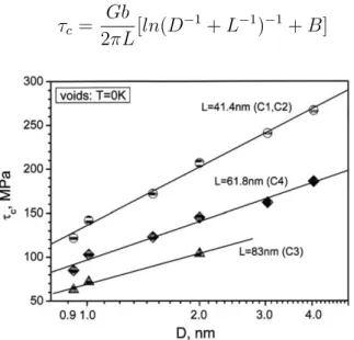
In a static simulation study at 0 K, Osetsky and Bacon investigated the critical shear stress dependence on void’s size and regular mean spacing as shown in Figure (1.22). It is clear that the critical shear stress is directly related to the size of the void. However, it is inversely proportional to the center-to-center spacing for a periodic row of voids in a crystal. Such dependence is formally predicted with Equation (1.3) [62]:
τc = Gb
2πL[ln(D
−1
+ L−1)−1+ B] (1.3)
Figure 1.22 – Dependence of the critical shear stress, τc using static MD simulations at T = 0 K on void’s diameter and dislocation length (after Osetsky et al. 2003) [40].
1.5.3
Solute Cluster
Solute atoms might be alloying elements intentionally added to adjust certain properties of materials. They can also be impurities from the elaboration process, or they
might act as sinks trapping solute atoms or cause them to repel. An extensive description of the formation process of solute clusters and their microstructural evolution under irradiation is reported in Vincent 2006 [65].
Becquart et Domain reported that the interaction between solute atoms and point defect (SIAs or vacancies) in iron has elastic and chemical parts. The size and the electronic structure of solute clusters determine the predominant effect. The elastic effect is found to be predominant for large clusters. The chemical effect is more important in case of different electronic structures between solute clusters and the matrix [42].
Pascuet et al. studied the segregation of solute atoms around an edge dislocation dipole using MD. They also investigated the effect of solute atoms on the pinning of dislocation lines [66]. A visualization of such segregation is shown in Figure (1.23).
Figure 1.23 – Solute atoms distribution around an edge dislocation dipole. The chemical composition of the alloy is Fe-0.7%Ni-1.4%Mn. The segregation temperature is 300 K. The dislocation dipole is presented in black lines, while colors of solute atoms are: Cu in
green, Mn in violet and Ni in red (after Pascuet et al. 2017) [66].
The segregation of solute atoms at the dislocation core plays an important role in the mobility of dislocations. The latter is reduced due to the presence of solute clusters that act as strong obstacles for edge dislocations [66].
1.5.4
Radiation-induced loops
There are two types of dislocation loops based on their formation mechanism. Loops are formed either due to a collapse of atomic planes over an agglomeration of vacancies, or by a set of self-interstitial atoms. Only the latter are observed in the RPV and they are
Figure 1.24 – TEM images of the microstructure of RPV steel at different irradiation doses. SIA loops are only observed at high irradiation dose > 0.2 dpa
(after Zinkle et Singh 2006) [50].
The majority of observed dislocation loops are interstitials and have a Burgers vector equal to 1/2[1 1 1] in {1 1 1} planes. MD simulations show that the lowest energy configuration of dislocation loops is for Burgers vector 1/2h1 1 1i with segments in h1 1 2i directions [68]. Other studies showed the existence of square dislocation loops of Burgers vector equal to h1 0 0i in the h1 0 0i or h1 1 0i directions [50, 69–71]. This configuration is most observed at high temperatures [72]. The evolution of density and size with radiation damage in dpa is depicted in Figure (1.25a) [50].
(a) (b)
Figure 1.25 – Experimental observation of the evolution of density and diameter of dislocation loops as function of displacement damage (dpa) when irradiated at T = 340 K
(after Zinkle et Singh 2006) [50].
Molecular dynamics is used to investigate the effect of loop’s size and orientation on the interaction mechanism with screw of edge dislocations. In the following, three main MD studies are discussed. The first study is focused on edge dislocations, while the second and third studies are focused on screw dislocations.
All of these studies used an interatomic potential for pure iron by Ackland et al. [61]. This interatomic potential is fitted to ab-initio simulations using the embedded atom
method (EAM). There are many other potentials used in the literature depending on
the chemical composition of the studied material [60, 73, 74]. However, the interatomic potential of Ackland et al. provides a better prediction of the dislocation core structure in good agreement with ab-initio simulations [41, 75, 76].
Interaction between edge dislocations and SIA loops
There are several factors that determine the nature of the interaction between a dislocation and a loop, such as the strain rate, the character of the dislocation (screw or edge), size and orientation of the loop [77]. Interactions between edge dislocations and radiation-induced defects are widely studied in literature compared to that of screw dislocations. A summary of such interactions in iron are found in Granberg 2016 and in Bacon et al. 2009 [38, 78].
A study by Bacon et al. shows the interaction between an edge dislocation with a hexagonal loop with b =1/2[1 1 1] and 1/2[1 1 1] of 37 and 331 SIAs. The EAM interatomic potential used in this study is Ackland et al. in [61]. They performed static and dynamic simulations at T = 0 K and at different temperatures in the range between 100-450 K. The applied strain rate in this study is 107 s−1. The initial configuration is shown in Figure
Figure 1.26 – Schematic representation of the initial configuration of the interaction between a b =1/2[1 1 1] edge dislocation and a b =1/2[1 1 1] hexagonal loop used in MD simulations. The applied shear direction is indicated with arrows on the top and bottom
of the simulation box (after Bacon et al. 2006) [79].
The primary results of static simulations at T = 0 K shows that the loop of 37 SIAs is transformed into a superjog of the same Burgers vector as the dislocation. The formation of the superjog in this case is done through the change of the crowdion axis of the loop from [1 1 1] to the [1 1 1] direction. A visualization of such interaction mechanism is also shown in Figure (1.27). In this case, the dislocation-superjog combination is glissile and can glide along the plane of the original dislocation.
Figure 1.27 – Different stages of static MD simulation at T = 0 K between an edge dislocation and 1/2[1 1 1] hexagonal loop of 37 SIAs. A glissile superjog is formed as a
Figure 1.28 – Different stages of dynamic simulation at T = 300 K between edge dislocation and a 1/2[1 1 1] hexagonal loop of 331 SIAs (after Bacon et al. 2006) [79].
A summary of the critical stress for different temperatures for small and large loops of 37 and 331 SIA, respectively, is shown in Figure (1.29). Two main results can be noted from this figure; i) temperature has nearly no effect on the critical stress for small loops of 37 SIAs, ii) for large loops of 331 SIAs, the critical stress decreases when temperature increases, iii) the critical stress of large loops is higher than that for small loops regardless of the temperature.
![Figure 1.1 – Schematic diagram of the reactor pressure vessel and the internal components including fuel and control rods (after Kok 2009) [5].](https://thumb-eu.123doks.com/thumbv2/123doknet/12878276.369819/28.892.284.610.566.967/figure-schematic-diagram-reactor-pressure-internal-components-including.webp)
![Figure 1.6 – Stress-strain curve for 16MND5 steel at different temperatures under a strain rate of 5 × 10 −4 s −1 (after Libert 2007) [18].](https://thumb-eu.123doks.com/thumbv2/123doknet/12878276.369819/33.892.236.655.466.716/figure-stress-strain-curve-different-temperatures-strain-libert.webp)


![Figure 1.11 – A screw dislocation part in a curved dislocation undergoes a cross-slip process to a secondary plane (after Hull et Bacon 2001) [28].](https://thumb-eu.123doks.com/thumbv2/123doknet/12878276.369819/37.892.256.635.136.397/figure-dislocation-curved-dislocation-undergoes-process-secondary-bacon.webp)


![Figure 1.28 – Different stages of dynamic simulation at T = 300 K between edge dislocation and a 1/2[1 1 1] hexagonal loop of 331 SIAs (after Bacon et al](https://thumb-eu.123doks.com/thumbv2/123doknet/12878276.369819/50.892.281.611.299.595/figure-different-stages-dynamic-simulation-dislocation-hexagonal-bacon.webp)
