HAL Id: tel-00783316
https://tel.archives-ouvertes.fr/tel-00783316
Submitted on 1 Aug 2013
HAL is a multi-disciplinary open access archive for the deposit and dissemination of sci-entific research documents, whether they are pub-lished or not. The documents may come from teaching and research institutions in France or abroad, or from public or private research centers.
L’archive ouverte pluridisciplinaire HAL, est destinée au dépôt et à la diffusion de documents scientifiques de niveau recherche, publiés ou non, émanant des établissements d’enseignement et de recherche français ou étrangers, des laboratoires publics ou privés.
Rheology and Magnetolysis of Tumor Cells
Biran Wang
To cite this version:
Biran Wang. Rheology and Magnetolysis of Tumor Cells. Biological Physics [physics.bio-ph]. Univer-sité Nice Sophia Antipolis, 2012. English. �tel-00783316�
UNIVERSITE DE NICE-SOPHIA ANTIPOLIS - UFR Sciences
Ecole Doctorale en Sciences Fondamentales et Appliquées
T H E S E
pour obtenir le titre de
Docteur en Sciences
de l'Université de Nice-Sophia Antipolis
Discipline: Physique
Présentée et soutenue par
Biran WANG
Rheology and Magnetolysis of Tumor Cells
Thèse dirigée par
: Georges BOSSISSoutenue le : 4-Décembre-2012
Jury :
Dr. Alain Ponton Directeur de recherche (Rapporteur) Dr. Olivier Sandre Chargé de Recherche (Rapporteur) Dr. Georges Bossis Directeur de recherche
Dr. Christophe Di-Giorgio Maître de conférences Dr. Pierre Vierling Directeur de recherche Dr. Andrey Zubarev Professeur
A
CKNOWLEDGMENTS
I would like to express my gratitude to my supervisor, Georges BOSSIS, for supporting me over the years, and for giving me so much freedom to explore and discover new areas of biophysics. I appreciate his vast knowledge and skill in many areas and his assistance in writing reports. My co-supervisor, Pierre VIERLING, has also been very supportive to me. To each of them I owe a great debt of gratitude for their patience, inspiration and friendship. A sincere acknowledgment goes to the external reading committee, Alain Ponton, Olivier Sandre and Andrey Zubarev, thanks to their availability and effort in reading my work.
The research that has gone into this thesis was very enjoyable. The “sixth floor” has provided an excellent environment for my research. I spent many enjoyable hours with the team; I cannot find words to express my gratitude to them, Alain, Aladine, Alexandrza, Audrey, Cecilia, Jacques, Olga, Pascal, Pavel, Romain and all the visitors, what a hot ambience!! We’ve chatted about politics, broken news and of cause also the latest ideas about experiences over a cup of coffee. Without this rich environment, I doubt that many of my experiences would have come to fruition.
I am indebted to my many colleagues in “downtown” LPMC, who supported me, first of all, the two directors of laboratory, Gérard and Fabrice, who received me very kindly.
I wish to thank the members of Administrative department of LPMC, Denise, Christine C, Christine B and Nathalie, which helped me a lot about administrative stuffs, since I’m a Chinese, I have ten times more administrative papers than the other colleagues; without them, I couldn’t finish my thesis in time, or ever could not start.
And of course, thanks go also to the member of technical services, mechanical workshop, chemical workshop, electrical workshop and computer department, without their help, lots of experiences would not be realized. A special memory goes to our respectable colleague, Dédé, who helped me a lot for the mechanical realization; he was really “a diamond of the first water”.
I would also like to thank the other members of LPMC, who helped me to make the transition from process engineer to biophysicist, and I appreciate that.
I would like to thank my many friends and colleagues at LCMBA, with whom I have had the pleasure of working over the years. These include Céline, Nicolas, Christophe and all the members of the LCMBA.
Thanks also to my family in China, who have been extremely understanding and supportive of my studies. I feel very lucky to have a family that shares my enthusiasm for academic pursuits.
Finally, I would especially like to thank my beautiful wife Juan, who has encouraged me so much over the years, and my adorable son Zhidao, who has given me biggest smell of the world every day, and my little Amy, who came out in time for her dad’s viva voce, it was them who given me the motivation to finish this thesis.
R
ÉSUMÉ COURT
(F
R
.
E
N
)
Les nanoparticules magnétiques peuvent être utilisées pour détruire des cellules cancéreuses. La connaissance des propriétés rhéologiques de ces cellules permet de modéliser le mouvement des particules sur la surface des membranes et de mieux comprendre les mécanismes en jeu. Une première approche fut d'utiliser des microsondes magnétiques pour déterminer les propriétés viscoélastiques du milieu cellulaire. Puis une technique plus directe à l'aide d'un AFM a été utilisée. Nous avons à cet effet développé une méthode générale d'analyse du mouvement de la pointe AFM pour les étapes d'indentation et de relaxation, ce qui permet une détermination plus précise des paramètres rhéologiques de cellules et en particulier de la lignée Hep-G2. La modélisation du comportement viscoélastique des cellules a ensuite permis de calculer l'indentation de ces cellules par des particules magnétiques soumise à un gradient de champ magnétique. Des nanoparticules de fer en forme de fuseau, recouvertes d'or, ainsi que des nanofibres de cobalt ont été synthétisées au laboratoire. Nous avons montré que l'application d'un champ magnétique de basse fréquence (quelques Hz) sur ces nanoparticules de fer pouvait "in vitro" détruire des cellules cancéreuses mais que, par contre, un champ constant n'avait pratiquement aucun effet. En s'appuyant sur la modélisation de l'indentation, on montre que seule la formation de clusters de particules peut expliquer ces résultats. A coté de la magnétolyse par voie mécanique, nous avons montré qu'il était aussi possible d'utiliser l'importante hystérésis magnétique des nanoparticules de cobalt pour le traitement par hyperthermie de cellules cancéreuses à des fréquences aussi basses que 10 kHz.
Magnetic nanoparticles can be used to destroy cancer cells. The knowledge of the rheological properties of the cancer cells allows to model the motion of the particles at the surface of the membrane and to get a better understanding of the mechanisms. A first approach was to use magnetic microprobes to determine the viscoelastic properties of a gel that represent the tumor cells. Then a more convenient AFM method has been employed. We have carried out a more general analysis of the AFM tip motion which contains both the indentation and relaxation steps, allowing a better determination of the rheological parameters, in particular of cancer cell called Hep-G2. The knowledge of the viscoelastic behavior of these cells allowed us to predict their indentation by magnetic particles submitted to an alternative field gradient. The synthesis of some of these particles such as: spindle-type iron and gold core-shell nanoparticles, and cobalt nanoneedles were carried out in our laboratory. We proved that the application of an alternative magnetic field of low frequency (a few Hertz) in the presence of magnetic microparticles was able "in vitro" to destroy cancer cells, and a constant magnetic field was far less efficient than an oscillating one. Based on the indentation model, we proposed that the magnetic field induces the formation of clusters of particles which are then large enough to damage the membranes of the cells. Besides magnetolysis by mechanical way we have also shown that cobalt nanoneedles presented an important hysteresis cycle which can be used for hyperthermia treatment of cancer cells at frequencies as low as 10 kHz.
A
BSTRACT
Magnetic nanoparticles can be used to destroy cancer cells by applying an external magnetic field at high frequency, which produces a local heating due to the lag between the magnetization and the field. More recently, some works have concluded that it was also possible to destroy the membranes of the cell thanks to a mechanical damage caused by the oscillating motion of the magnetic nanoparticles. The knowledge of the rheological properties of the cancer cells allows to model the motion of the particles at the surface of the membrane and to get a better understanding of the mechanism, which come in play. A first approach was investigated based on the use of magnetic microprobes whose motion can be followed with a videocamera; although giving a good representation of the viscoelastic properties of a gel, it is difficult to apply on biological cells. A more convenient method lies on the use of atomic force microscopy (AFM) by looking at the relaxation of the force when a constant position of the AFM head is maintained or at the evolution of the indentation when a constant force is maintained. In both cases the analysis rests on the hypothesis that the motion of the probe inside the tissue before the relaxation step is realized in a time, which is much smaller than the characteristic relaxation time of the material. In this study we carry out a more general analysis of the probe motion, which contains both the indentation and relaxation steps, allowing a better determination of the rheological parameters. This analysis contains a correction of the Hertz model for large indentation and also a correction due to the finite thickness of the biological material; it can be applied to determine the parameters representing any kind of linear viscoelastic model. This approach is then used to model the rheological behavior of one kind of cancer cell called Hep-G2. For this kind of cell, a power law model does not well describe the low and high frequency modulus contrary to a generalized Maxwell model.
The knowledge of the viscoelastic behavior of the cells allowed us to predict the indentation of cells by magnetic microparticles submitted to an alternative field gradient. The synthesis of some of these particles such as: spindle-type iron and gold core-shell nanoparticles, and cobalt nanoneedles, were carried out in the LPMC. We proved that the application of an alternative magnetic field of low frequency (a few Hertz) in the presence of magnetic nanoparticles was able "in vitro" to destroy cancer cells. Also it was shown that a constant magnetic field was
far less efficient than an oscillating one. The mechanical model of indentation of the cell by the particles has demonstrated that the indentation by a single particle, in our experimental conditions, was in the range of the nanometer. Using an AFM tip as indenter, the lysis of the membrane needed amplitudes of indentation at least one order of magnitude larger. The explanation, which is proposed, based on observations under microscope before and after the application of the field, is that the magnetic field induces the formation of clusters of particles, which are then large enough to damage the membranes of the cells.
Besides magnetolysis by mechanical way we have also shown that cobalt nanoneedles presented an important hysteresis cycle, which can be used for hyperthermia treatment of cancer cells at frequencies as low as 10 kHz, compared to a few hundred kHz in usual conditions.
T
ABLE OF
C
ONTENTS
ACKNOWLEDGMENTS ... I RÉSUMÉ COURT (FR. EN) ... III ABSTRACT ... IV LIST OF ILLUSTRATIONS ... IX LIST OF TABLE ... XIII
1. INTRODUCTION (FR. EN) ... 1
2. STATE OF THE ART ... 3
2.1. CANCER ... 3
2.1.1. Tumor, cancer, metastasis ... 3
2.1.2. Number and cost about cancer ... 4
2.1.3. Classic treatments of cancer ... 5
2.1.4. Hyperthermia therapy ... 6
2.1.5. Magnetic hyperthermia ... 8
2.1.6. Composition of tumor cell ... 10
2.2. RHEOLOGY ... 10
2.2.1. Stress, strain and strain rate ... 10
2.2.2. Newtonian fluid, Hookean solid and yield stress ... 12
2.2.3. Maxwell model and Kelvin-Voigt Model ... 14
2.2.4. More complex model ... 16
2.3. MAGNETIC NANOPARTICLES ... 18
2.4. ATOMIC FORCE MICROSCOPY (AFM) ... 18
2.4.1. Basic principles ... 19
2.4.2. Force spectroscopy ... 20
3. USE OF MAGNETIC PARTICLES TO PROBE THE RHEOLOGY ... 22
3.1. MOTION OF A FIBER IN A NEWTONIAN FLUID ... 22
3.1.1. Experimental setup ... 22
3.1.2. Rotation ... 23
3.1.3. Translation of a probe in magnetic field gradient ... 34
3.2. VISCOELASTIC MODEL ... 38
3.2.1. Materials and experimental setup ... 40
3.2.3. Use of a microprobe to obtain the rheological properties ... 43
3.2.4. Summary of the results with Carbopol ... 52
3.3. DISCUSSION AND CONCLUSION ... 52
4. RHEOLOGICAL PROPERTY OF CANCER CELL BY AFM ... 54
4.1. INTRODUCTION ... 54
4.2. MATERIALS AND METHODS ... 56
4.2.1. Cancer cells ... 57
4.2.2. Force spectroscopy with AFM ... 59
4.3. MICRORHEOLOGY WITH A SPHERICAL INDENTER ... 62
4.3.1. Time dependent Hertz model ... 62
4.3.2. Corrections to the Hertz model... 65
4.3.3. Penetration of a sphere in viscoelastic medium ... 68
4.3.4. Deriving the material properties ... 71
4.4. RESULTS ... 72
4.4.1. Response function G(t) of the cells Hep G2 ... 76
4.5. CONCLUSIONS ... 83
5. SYNTHESIS OF MAGNETIC PARTICLES ... 85
5.1. SPINDLE-TYPE IRON@GOLD CORE-SHELL NANOPARTICLES ... 85
5.1.1. Introduction ... 85
5.1.2. Experimental synthesis ... 86
5.1.3. Surface modification of iron particles... 89
5.1.4. Results and discussion ... 90
5.1.5. Synthesis of pegylated Fe@Au NPs and characterization ... 96
5.2. COBALT NANOFIBERS ... 97
5.2.1. Polyol method... 98
5.2.2. Description of synthesis and results ... 98
5.3. IRON AND IRON OXIDE PARTICLES ... 101
5.3.1. Iron particles ... 101
5.3.2. Iron oxide particles ... 103
5.4. CONCLUSIONS ... 104
6. MECHANICAL DAMAGE INDUCED BY AN ALTERNATING MAGNETIC FIELD ... 105
6.1. INTRODUCTION ... 105
6.2. MATERIALS AND METHODS ... 107
6.2.1. Experimental Setup ... 108
6.4. THEORY... 115
6.4.1. Generalization of the Hertz theory ... 118
6.5. DISCUSSION ... 120
6.6. CONCLUSIONS ... 124
7. MAGNETIC HYPERTHERMIA ... 126
7.1. INTRODUCTION ... 126
7.2. EXPERIMENTAL SETUP, MATERIAL AND METHODS ... 127
7.3. DETERMINATION OF THERMAL PROPERTIES... 128
7.3.1. Effective thermal conductivity ... 128
7.3.2. (Mass) Specific heat capacity ... 129
7.4. ENERGY DISSIPATED BY HYSTERESIS ... 130
7.5. SOLIDWORKS SIMULATION OF TEMPERATURE RISE... 134
7.5.1. Results for the heating power ... 136
7.5.2. Power produced by the rotation of the particles ... 139
7.5.3. Simulation of the heating of a tumor ... 141
7.6. CONCLUSION ... 142
8. CONCLUSION AND PERSPECTIVES(EN. FR) ... 144
L
IST OF
I
LLUSTRATIONS
FIG.2-1:A PLOT OF MAGNETIZATION M AGAINST MAGNETIC FIELD H CALCULATED USING A THEORETICAL MODEL. ... 9
FIG.2-2:AXIAL STRESS IN A PRISMATIC BAR AXIALLY LOADED ... 11
FIG.2-3:SHEAR STRESS IN A PRISMATIC BAR.THE STRESS IS NOT NECESSARILY UNIFORM. ... 11
FIG.2-4:TWO-DIMENSIONAL GEOMETRIC DEFORMATION OF AN INFINITESIMAL MATERIAL ELEMENT ... 12
FIG.2-5 :MODEL OF A NEWTONIAN FLUID, A DASHPOT ... 13
FIG.2-6 :MODEL OF AN ELASTIC SOLID, A SPRING ... 13
FIG.2-7 :MODEL OF A YIELD STRESS, A SWITCH ... 14
FIG.2-8 :MAXWELL MODEL, A DASHPOT AND A SPRING IN SERIES ... 14
FIG.2-9 :MODEL OF KELVIN-VOIGT, A DASHPOT AND A SPRING IN PARALLEL ... 15
FIG.2-10 :MODEL OF BINGHAM, A DASHPOT AND A SWITCH IN PARALLEL ... 16
FIG.2-11 :SCHEMATIC REPRESENTATION OF THE ZENER MODEL ... 17
FIG.2-12 :SCHEMATIC OF MAXWELL-WIECHERT MODEL ... 17
FIG.2-13:BLOCK DIAGRAM OF ATOMIC FORCE MICROSCOPE ... 19
FIG.3-1 :EXPERIMENTAL SETUP ... 23
FIG.3-2.COMPARISON OF THE DIFFERENT MODELS USED FOR THE HYDRODYNAMIC TORQUE ... 25
FIG.3-3 :A ROD-LIKE FIBER IN A NEWTONIAN FLUID UNDER AN ALTERNATIVE MAGNETIC FIELD ... 26
FIG.3-4:SCHEMATIC VIEW OF THE FIBER AT THE INTERFACE OF TWO FLUIDS ... 28
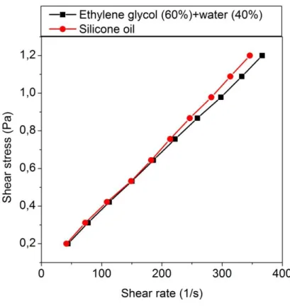
FIG.3-5 :RHEOLOGICAL PROPERTY OF SILICONE OIL AND OF THE MIXTURE OF ETHYLENE GLYCOL (60%) WITH WATER ... 29
FIG.3-6.MAGNETIZATION CURVE M= F (H), FOR A PURE NICKEL FIBER, THE RED DOTS REPRESENT THE MAGNETIZATION CYCLE AT LOW FIELD AMPLITUDE AFTER THE MAGNETIZATION AT HIGH FIELD ... 30
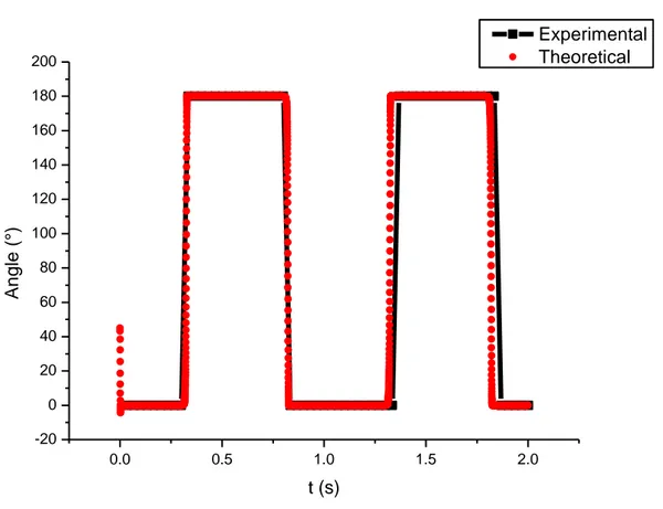
FIG.3-7.COMPARISON OF EXPERIMENTAL AND THEORETICAL ANGULAR ROTATION, FOR F=1HZ,H=31G ... 31
FIG.3-8.OSCILLATION ZONE IN THE PLANE, Γ, NORMALIZED FREQUENCY F* ... 33
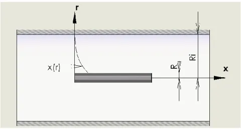
FIG.3-9.SIMPLIFIED EXPERIMENT SETUP FOR TRANSLATION (LEFT), ONE FIBER IN A VISCOUS FLUID UNDER A MAGNETIC FIELD GRADIENT (RIGHT) ... 35
FIG.3-10 :MEASUREMENT OF MAGNETIC FIELD GRADIENT ... 37
FIG.3-11 :THE TRANSLATIONAL MOTION OF A MAGNETIC FIBER VERSUS TIME ... 38
FIG.3-12:SIMPLIFIED EXPERIMENTAL SETUP, EXPERIENCE WITH THE COBALT PLATE BONDED TO GLASS SLIDE, ON CARBOPOL ... 41
FIG.3-13:SHEAR STRESS/SHEAR RATE OF CARBOPOL, MEASURED BY ROTATIONAL RHEOMETRY; THE BLUE LINE IS A BINGHAM FIT OF THE DECREASING STRESS WITH B=70PA AND =16.7PA ... 42
FIG.3-14:STORAGE MODULUS G’ AND LOSS MODULUS G” OF CARBOPOL ... 43
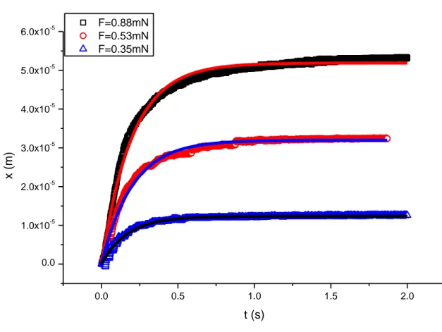
FIG.3-15:DISPLACEMENT OF THE IRON BALL VS. TIME, AND FITTING CURVE, FOR DIFFERENT FREQUENCIES AND FIELD ... 47
FIG.3-16:MEASUREMENT SETUP OF THE MAGNETIC FORCE, HERE FOR A THIN SLICE OF COBALT; RIGHT FIGURE IS THE MAGNETIC FORCE AS A FUNCTION OF THE DISTANCE(FITTED BY AN EXPONENTIALLY DECREASING FUNCTION) ... 48
FIG.3-18: THE NICKEL FIBER TOURING BY CARBOPOL IN A GLASS TUBE ... 50
FIG.3-19:THE DISPLACEMENT OF THE NICKEL FIBER VERSUS TIME ... 51
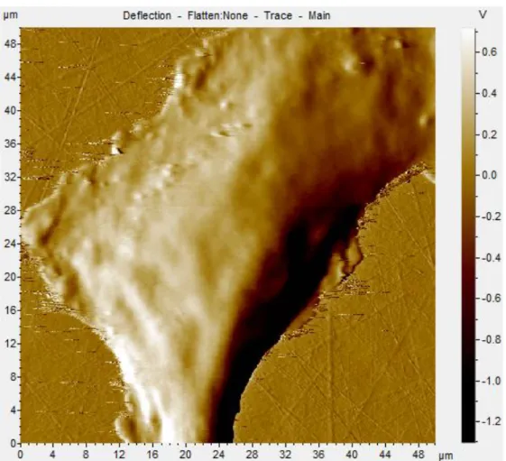
FIG.4-1:AN AFM IMAGE OF HEP G2 ... 57
FIG.4-2:AN AFM IMAGE OF BNLCL.2 ... 58
FIG.4-3:THE ORGANIZATION OF ACTIN (LEFT) AND MICROTUBULES (RIGHT) OF HEP G2 SHOWN BY FLUORESCENT MICROSCOPY ... 59
FIG.4-4:AFM SPHERICAL PROBE FOR RHEOLOGICAL STUDY ... 60
FIG.4-5:LEFT IS AN INDENTATION CYCLE; RIGHT IS THE METHOD FOR THE DETERMINATION OF THE CONTACT POINT AND OF THE FORCE/INDENTATION CURVE.UPPER GRAPH: EXPERIMENTAL FORCE VERSUS TIME.LOWER GRAPH: MOTION OF THE CANTILEVER HEAD VERSUS TIME... 62
FIG.4-6:MODELING OF SPHERICAL AFM PROBE CONTACT WITH CANCER CELL SURFACE,R IS THE RADIUS OF THE PROBE, H THE INDENTATION OF THE PROBE ... 63
FIG.4-7:SCHEMATIC REPRESENTATION OF THE GENERALIZED MAXWELL MODEL ... 64
FIG.4-8:CALCULATION OF THE FORCE WITH RESPECT TO THE INDENTATION USING ABAQUS, THE HERTZ MODEL AND THE GENERALIZED HERTZ MODEL IN THE CASE OF AN INFINITE ELASTIC PLATE AND OF A 10µM THICKNESS PLATE ... 67
FIG.4-9:CALCULATION OF THE FORCE WITH RESPECT TO THE INDENTATION IN A VISCOELASTIC MEDIUM WITH A SPHERICAL PROBE MOUNTED ON A SPRING USING THE SOFTWARE ABAQUS ... 69
FIG.4-10:COMPARISON BETWEEN FEM RESULT AND THE SOLUTION OF EQ.(4.29) FOR THE INDENTATION VERSUS TIME IN DISKS OF DIFFERENT THICKNESSES ... 70
FIG.4-11:MAXIMUM AND AVERAGE STRESS WITH RESPECT TO THE INDENTATION DEPTH FOR A PURELY ELASTIC MEDIUM; THE DIAMETER OF THE BEAD IS 5µM AND THE THICKNESS OF THE LAYER IS 10µM; THE INSERT IS THE RATIO OF MAXIMUM STRESS TO AVERAGE STRESS ... 71
FIG.4-12 THE MAP OF YOUNG'S MODULUS OF BNLC2 ... 74
FIG.4-13:AFM TOPOGRAPHY OF HEP G2 CELL, THE POINT A TO G ARE THE PLACE WHERE THE MEASUREMENTS HAVE BEEN CARRIED OUT ... 75
FIG.4-14:YOUNG’S MODULUS VERSUS INDENTATION VELOCITY.IN THE INSERT: FORCE VERSUS INDENTATION FOR TWO DIFFERENT VELOCITIES (V=100µM/S AND 100NM/S) AND THEIR FIT BY EQ.(4.22) ... 76
FIG.4-15:APPLIED FORCE (IN RED) VERSUS TIME DURING AN INDENTATION WITH A VELOCITY: V=0.25µM/S AND A MAXIMUM INDENTATION DEPTH: HS=1.08µM .THE BLUE TRIANGLES REPRESENT A FIT WITH A POWER LAW FOR G(T) AND THE BLACK CIRCLES A FIT WITH A ONE BRANCH MAXWELL MODEL ... 77
FIG.4-16:RAPID INDENTATION: APPLIED FORCE VERSUS TIME DURING AN INDENTATION WITH A VELOCITY: V=250µM/S.RED DOTS REPRESENT A FIT WITH 3 PARAMETERS (THE ZENER MODEL) FOR G(T) AND THE BLUE TRIANGLES A FIT WITH 5 PARAMETERS (TWO MAXWELL BRANCHES) ... 78
FIG.4-17:SAME CONDITIONS AS IN FIG.4-16COMPARISON BETWEEN A FIT WITH TWO MAXWELL BRANCHES AND A FIT WITH A POWER LAW ... 81
FIG.4-18:FREQUENCY DEPENDENCE OF THE REAL PART OF THE SHEAR MODULUS:G'() DEDUCED FROM THE FIT OF G(T) BY DIFFERENT MODELS.BLACK LINE: POWER LAW MODEL (EQ.(4.44)), REDLINE:MAXWELL MODEL WITH TWO BRANCHES (EQ.(4.42)),BLUE LINE:MAXWELL MODEL WITH THREE BRANCHES ... 82
FIG.5-2:FURNACE SCHEME OF -FE2O3 PARTICLES’ REDUCTION INTO Α-FE(0)NPS. ... 89
FIG.5-3:TEM PICTURES OF (A) Α-FE2O3 AND (B) Α-FE(0)NPS.(C)IR SPECTRUM OF Α-FE2O3(BLACK LINE) AND Α-FE(0)NPS (RED LINE) ... 91
FIG.5-4:EDX SPECTRUM OF FE@AU NPS, INSET SEM IMAGE OF ACICULAR FE@AU NPS ... 92
FIG.5-5:(A)MAGNETIZATION CURVE OF Α-FE,(BLACK SQUARED DOTS)(B)MAGNETIZATION CURVE OF FE@AU,(RED TRIANGULAR DOTS) ... 93
FIG.5-6:CONFOCAL MICROSCOPY 3D-PICTURE OF FE@AU-S-PEG5000-FLUORESCEIN NPS IN EMISSION MODE (GREEN CHANNEL).THE BOUNDING BOX DISPLAYS XYZ COORDINATE SYSTEM AS WELL AS UNITS (SCALE IN µM). ... 97
FIG.5-7:EXPERIMENTAL SETUP FOR THE SYNTHESIS OF COBALT NANOPARTICLES ... 99
FIG.5-8:THE TEM IMAGE OF COBALT NANOWIRES. ... 100
FIG.5-9 MAGNETISATION CYCLE OF COBALT NANOPARTICLES;H IS IN OERSTED ... 101
FIG.5-10: THE SEM IMAGES OF BASF PARTICLES ... 102
FIG.5-11MAGNETIZATION CURVE OF BASF PARTICLES (HQ GRADE) ... 102
FIG.5-12:SEM VIEW OF IRON OXIDE PARTICLES ... 103
FIG.5-13:MAGNETIZATION CURVE OF IRON OXIDE PARTICLES ... 103
FIG.6-1:EXPERIMENTAL SETUP ... 108
FIG.6-2:UPPER GRAPH:MEASUREMENT OF MAGNETIC FIELD VS. DISTANCE BETWEEN MAGNET AND CELLS.LOWER GRAPH: MAGNETIC FIELD VS. TIME FOR A FREQUENCY OF 2HZ) ... 110
FIG.6-3:THE RESULT OF MORTALITY TEST BY FLOW CYTOMETRY, WITHOUT FIELD (LEFT) AND WITH FIELD (RIGHT) ... 113
FIG.6-4:THE RESULT OF MORTALITY TEST, WITH SPINDLE-TYPE NANOPARTICLE ... 114
FIG.6-5:THE RESULT OF MORTALITY TEST WITH SPHERICAL MICROPARTICLE.THE LOWER POINTS AT ZERO HZ ARE THE REFERENCE RESULTS WITH NO FIELD APPLIED ON THE MAGNETIC PARTICLES; THE UPPER POINTS AT 0HZ CORRESPOND TO AN EXPOSURE TO THE CONSTANT MAXIMUM FIELD ... 114
FIG.6-6:CONICAL PARTICLES ... 116
FIG.6-7:A SCHEMATIC OF THE ZENER MODEL ... 117
FIG.6-8:COMPARISON BETWEEN EQ.(6.19) AND FEM RESULTS FOR A ZENER MODEL WITH THE PARAMETERS G0=210PA,G1= 181PA, Τ1=5.6S ... 118
FIG.6-9:AMPLITUDE OF THE OSCILLATION VERSUS ΩΤ UPPER CURVE SPHERICAL PARTICLE; LOWER CURVE SPINDLE LIKE PARTICLE ... 119
FIG.6-10:A CONICAL AFM PROBE, WITH THE SAME OVERALL DIMENSION AS A SPINDLE TYPE MAGNETIC PARTICLE... 121
FIG.6-11:INDENTATION WITH A CONICAL TIP DURING 20MN (UPPER PART)RESULT AFTER WAITING 15MN AND 1H (LOWER PART) ... 122
FIG.6-12:THE RESULT OF MORTALITY TEST BY SPHERICAL TIPS ... 123
FIG.6-13:THE PHOTO OF SPHERICAL PARTICLES AND CELLS BEFORE (UPPER PART) AND AFTER (LOWER PART) THE APPLICATION OF THE OSCILLATING FIELD, AVERAGE CELL DIAMETER IS 25µM THE BLUE STAINING INDICATES THE DEATH OF THE CELL ... 124
FIG.7-1 :EXPERIMENTAL SETUP FOR HYPERTHERMIA ... 127 FIG.7-2:COMPARISON BETWEEN MAXWELL MODEL AND THE NUMERICAL RESULT OF MERCIER ET AL FOR THE RELATIVE THERMAL
FIG.7-3:HYSTERESIS LOOP, THE DISSIPATED ENERGY IS THE AREA UNDER RED LINE MINUS THE AREA UNDER BLUE LINE.HERE FOR
COBALT NANOWIRES ... 130
FIG.7-4:HYSTERESIS LOOP OF COBALT NANOWIRES AT DIFFERENT FIELDS ... 131
FIG.7-5:HYSTERESIS LOOP OF IRON OXIDE AT DIFFERENT FIELDS ... 132
FIG.7-6:THE FITTING OF DISSIPATED ENERGY VERSUS MAGNETIC FIELD, TO EXTRAPOLATE THE DISSIPATED ENERGY ... 133
FIG.7-7:SIMULATION BY SOLIDWORKS, UPPER LEFT: CREATION OF MODEL, UPPER RIGHT: MESHING; LOWER FIGURE: THE RESULT OF SIMULATION ... 135
FIG.7-8:TEMPERATURE RISE VERSUS TIME, COMPARISON OF EXPERIMENTAL AND SIMULATION RESULTS FOR IRON OXIDE POWDER WITH AND WITHOUT ETHANOL, THE CONDITIONS OF EXPERIMENT: F=5 KHZ,H=12KA/M ... 137
FIG.7-9:INCREASE OF TEMPERATURE VERSUS TIME, THE COMPARISON OF EXPERIMENTAL AND SIMULATION RESULT OF COBALT POWDER, SAME CONDITION AS IN FIG.7-8 ... 138
FIG.7-10:TEMPERATURE RISE OF COBALT NANOWIRES POWDERS VERSUS TIME, FOR DIFFERENT FREQUENCIES OF THE APPLIED MAGNETIC FIELD (5,10,20 KHZ) ... 138
FIG.7-11.POWER DISSIPATED BY ROTATION FOR 0=30°H=12KA/M MR=250KA/M.=10PA.S THE BLUE LINE IS THE LIMIT PREDICTED BY EQ.(7.15) ... 141
FIG.7-12:SIMULATION OF HYPERTHERMIA IN CANCER TREATMENT, THE LEFT FIGURE REPRESENTS A TUMOR OF 1CM3 IN A SPHERICAL ENVIRONMENT (DIAMETER OF 10CM)OF WATER, THE RIGHT FIGURE IS THE RESULT OF SIMULATION (CROSS-SECTIONAL VIEW)AFTER 2MN ... 142
L
IST OF
T
ABLE
TAB.2-1:ESTIMATED GROSS MOLECULAR CONTENT OF A TYPICAL 20 MICROMETER HUMAN CELL ... 10
TAB.3-1: THE VALUE OF THE PARAMETERS USED TO CALCULATE THE VELOCITY ... 37
TAB.3-2 SUMMARY OF THE RESULTS OBTAINED WITH THE 3 MICROPROBES AND CONVENTIONAL RHEOMETRY... 52
TAB.5-1:MAGNETIC PROPERTIES OF FE AND FE@AU NPS DETERMINED FROM HYSTERESIS LOOPS ... 93
TAB.7-1:DISSPATED ENERGY FROM EQ.(7.6); LEFT IS IRON OXIDE AND RIGHT IS COBALT NANOWIRES... 132
TAB.7-2:THE TABLE OF MATERIAL PROPERTIES FOR SIMULATION ... 136
1.
I
NTRODUCTION
(F
R
.
E
N
)
知己知彼 百战不殆
«Qui connaît son ennemi comme il se connaît, en cent combats ne sera point défait» - 孙子兵法- Sun Tzu, L'Art de la guerre
Le cancer est l’ennemi public N° 1 de la société, de nombreuses stratégies ont été développées pour lutter contre lui, l’une d’entre elles est basée sur l'utilisation de nanoparticules magnétiques. Des nanoparticules magnétiques peuvent se lier à la membrane cellulaire, si leur surface a été recouverte de ligands appropriés. En utilisant un champ magnétique alternatif, il est possible de faire tourner les particules et /ou leur aimantation interne, ce qui entraîne une dissipation d'énergie et un échauffement local qui peut être utilisé pour détruire les tumeurs. Néanmoins, l'hyperthermie est difficile à réguler parce que les cellules tumorales ne sont que légèrement plus sensibles à l'élévation de température que les cellules saines. L'utilisation de nanoparticules allongées à la place de nanoparticules sphériques pourrait permettre de combiner l'effet thermique et l'endommagement mécanique.
Comme l'indique le titre de cette thèse, Rhéologie et magnétolyse des cellules tumorales, ce travail a deux objectifs principaux. La première porte sur l'étude des propriétés rhéologiques des cellules tumorales, et le second sur l'utilisation de nano/micro particules magnétiques pour détruire ces cellules.
Il y a un célèbre proverbe chinois de Sun Tzu, ancien général chinois, stratége et philosophe auteur de L'Art de la Guerre, qui dit: «Qui connaît son ennemi comme il se connaît, en cent combats ne sera point défait. »
Dans le but de combattre cet ennemi qu'est la cellule tumorale par des moyens de microécanique, la première partie de ce travail porte sur la manière d'obtenir des informations
mouvement de microsondes pour obtenir leurs propriétés rhéologiques. Dans une première approche en utilisant un fluide newtonien, nous avons suivi le mouvement d'une aiguille en présence d'un champ alternatif et comparé ce mouvement angulaire avec un modèle micromécanique qui prédit l'intensité du champ magnétique et la fréquence nécessaires pour obtenir un mouvement oscillatoire des aiguilles. Nous avons également utilisé le mouvement de translation sous un gradient de champ magnétique pour mesurer la viscosité. Ensuite, nous avons étudié le mouvement de petites sondes magnétiques (sphère, fibre et plaque) dans un milieu viscoélastique montrant qu'il était possible d'obtenir les propriétés viscoélastiques d'un gel par cette méthode décrite dans le chapitre 3.
Bien qu’elles soient réalisables en principe, ces expériences sont difficiles à conduire à l'échelle de cellules avec des particules de l'ordre du micron; il est plus facile d'utiliser des particules microniques attachées au cantilever d’un AFM afin de mesurer les propriétés viscoélastiques de cellules tumorales. Cette méthode et les résultats obtenus sont présentés au chapitre 4.
La deuxième partie de ce travail est consacrée à l'utilisation de micro ou nanoparticules magnétiques dans le but de détruire les cellules soit mécaniquement, soit par un effet thermique. Le chapitre 5 décrit la synthèse et la caractérisation de ces particules. Dans le chapitre 6, nous étudions l'effet sur la mortalité des cellules cancéreuses, d'un gradient de champ alternatif appliqué sur les microparticules qui ont sédimenté sur la surface des cellules. Dans le dernier chapitre, nous avons examiné la possibilité d'élever la température des cellules avec des nanoparticules d’environ 100 nm, plus grandes que celles d'un ferrofluide (environ 10 nm) qui sont généralement considérées pour des applications d'hyperthermie, mais encore assez petites pour diffuser à l'intérieur du tissu tumoral.
«If you know the enemy and know yourself, you need not fear the result of a hundred battles. »
Sa Tzu, The Art of War
Cancer is the N°1 public enemy for the society and numerous strategies have been developed to fight against it. One of them is based on the use of magnetic nanoparticles. Magnetic nanoparticles can bind to the cell membrane if their surface has been coated with appropriated ligands. Using an alternating magnetic field, it is possible to rotate the particles and/or their internal magnetization, resulting in energy dissipation and local temperature rise that can be used to destroy tumors. Nevertheless, hyperthermia is difficult to regulate because the tumor cells are only slightly more sensitive to temperature rise than healthy cells. The use of elongated nanoparticles instead of spherical one could provide both thermal and mechanical damage.
As indicated by the title of this thesis, Rheology and magnetolysis of tumor cell, there are two main objectives of this work, the first one about the study of the rheological properties of tumor cells, and the second one on the use of magnetic micro or nanoparticles to destroy these cells.
There is one celebrated saying about enemy by Sun Tzu, an ancient Chinese military general, strategist and philosopher, author of The Art of War, «If you know the enemy and know yourself, you need not fear the result of a hundred battles. »
Since we want to kill this enemy mechanically, the first part of this work is about the way to obtain information on the mechanical properties of the tumor cells. We have started with the idea to follow the motion of microprobes to get the rheological behavior. In a first approach on a Newtonian fluid, we have followed the motion of a needle in the presence of an alternative field and compared this angular motion with the prediction of a micromechanical model, which gives the magnetic field intensity and the frequency necessary to obtain a swinging motion of the needles; also the translational motion under a magnetic field gradient was used to measure the viscosity. In a second step we have studied the motion of small magnetic probes (sphere, needle or plate) in a viscoelastic medium showing that it was
chapter 3. Although feasible in principle these experiments are difficult to make at the scale of cells with probes of size around one micron, so finally we performed experiments with a micronic particle attached to an AFM cantilever in order to measure the viscoelastic properties of tumor cells; the method and the results are presented in chapter 4.
The second part of this work is devoted to the use of magnetic micro or nanoparticles which will be used for the purpose of destroying the cells either mechanically or by a heating effect. Chapter 5 describes the synthesis and characterization of these particles. In chapter 6, we study the effect, on the viability of cancer cells, of an alternative field gradient applied on the microparticles, which were sediment on the surface of the cells. In the last chapter, we examine the possibility to heat the cells with nanoparticles whose sizes (about 100 nm) are larger than the ones of a ferrofluid (about 10 nm), which are usually considered for hyperthermia applications, but still small enough to diffuse inside the tumor tissue.
2.
S
TATE OF THE ART
2.1. Cancer
2.1.1. Tumor, cancer, metastasis
The term tumor is, in medicine, an increasing volume of tissue, clearly delineated without specifying cause. It is a formation of new body tissue (neoplasm) that occurs as a result of a deregulation of cell growth, like benign or malignant.
Neoplasm is an abnormal mass of tissue as a result of neoplasia. Neoplasia ("new growth" in Greek) is the abnormal proliferation of cells. The growth of neoplastic cells exceeds and is not coordinated with that of the normal tissues around it. The growth persists in the same excessive manner even after cessation of the stimuli. It usually causes a lump or tumor. Neoplasms may be benign, pre-malignant (carcinoma in situ) or malignant (cancer).
Benign tumors are usually not harmful and grow slowly. They are also localized and has not spread (metastasize) to other parts of the body or invaded and destroyed nearby tissue. Benign tumors affecting the skin are still often seen as unsightly and can lead to ablation. However, a benign tumor can cause serious complications (compression, ignition ...) by its mechanical action.
Potentially malignant neoplasms include carcinoma in situ. They do not invade and destroy but, given enough time, will transform into a cancer.
Malignant neoplasms are commonly called cancer, they are ambitious. Unlike benign tumors that generally stay in place, malignant tumors have two goals in life: to survive and to conquer new territory. They invade and destroy the surrounding tissue, may form metastases and eventually kill the host.
Metastasis is the spread of a disease from one organ or part to another non-adjacent organ or part. A cancer can affect any type of tissue. Depending on the location of the tumor and function of the affected tissue, it can lead to organ dysfunction and affect the whole body and
Determining what causes cancer is complex. Many things are known to increase the risk of cancer, including tobacco use, certain infections, radiation, lack of physical activity, poor diet and obesity, and environmental pollutants(1). The tumors occur in all living beings, including plants.
2.1.2. Number and cost about cancer
A study by the International Agency for Research on Cancer (IARC, an offshoot of the World Health Organization), cancer killed 7.6 million people, mostly in developing countries in 2008 , 12.7 million new cases of cancer were diagnosed, while in 2000 the number was 10 million and in 1975 it was 5.9 million(2).
As to France, there are 146,500 cancer deaths estimated in 2010, 84,500 men and 62,000 women. For the period 2003-2007, cancer is the leading cause of death in men and second in women(3).
The most commonly diagnosed cancers in the world are those of the lung (12.7%), breast (10.9%) and colorectal cancer (9.7%). The most common deaths are caused by lung cancer (18.2%), stomach cancer (9.7%) and liver cancer (9.2%)(2).
In France, in men, lung cancer is the leading cause of death, followed by colorectal cancer and prostate cancer. In women, it is breast cancer followed by colorectal cancer and lung cancer(3).
Chemotherapy and major surgery and the long-term treatment of cancer are one of the most financially costly diseases to society. The social cost of cancer is difficult to assess, but is important and continues to grow(4).
In France in the 2000s, about 280,000 new cases were detected per year, with a steady rise in the number of cases (358,000 new cases expected in 2010 according to the modeling of the INVS (made necessary by the fact that in France, only about 20% of the population is concerned by a cancer registry) annual cost estimated to be 30 billion Euros in 2004. 730 million Euros were granted in the 2nd Plan of cancer (2009-2013) of which 95 million for research and 400 million for care. The research also focuses on ways to reduce the socio-economic costs of the disease and the health care(3).
2.1.3. Classic treatments of cancer
Surgery In theory, non-hematological cancers can be cured if entirely removed by surgery,
but this is not always possible. When the cancer has metastasized to other sites in the body prior to surgery, complete surgical excision is usually impossible.
Chemotherapy is the treatment of cancer with drugs ("anticancer drugs") that can destroy
cancer cells. In current usage, the term "chemotherapy" usually refers to cytotoxic drugs which affect rapidly dividing cells in general, in contrast with targeted therapy. Because some drugs work better together than alone, two or more drugs are often given at the same time. This is called "combination chemotherapy"; most chemotherapy regimens are given in a combination.
This technique has a range of side effects that depend on the type of medications used. The common side effects include: depression of the immune system, physically exhausting for the patient, the tendency to bleed easily, the gastrointestinal distress, like nausea and vomiting, and hair loss, and so on.
Hormonal therapy is used for several types of cancers derived from hormonally responsive
tissues, including the breast, prostate, endometrium, and adrenal cortex. Because steroid hormones are powerful drivers of gene expression in certain cancer cells, changing the levels or activity of certain hormones can cause certain cancers to cease growing, or even undergo cell death.
Radiation therapy is the use of ionizing radiation to kill cancer cells and shrink tumors. The
effects of radiation therapy are localized and confined to the region being treated. Radiation therapy injures or destroys cells in the area being treated (the "target tissue") by damaging their genetic material, making it impossible for these cells to continue to grow and divide. Although radiation damages both cancer cells and normal cells, most normal cells can recover from the effects of radiation and function properly. The goal of radiation therapy is to damage as many cancer cells as possible, while limiting harm to nearby healthy tissue. Hence, it is given in many fractions, allowing healthy tissue to recover between fractions. Thus, as with every form of treatment, radiation therapy is not without its side effects.
Immunotherapy is the use of the immune system to reject cancer. The main premise is
stimulating the patient's immune system to attack the malignant tumor cells that are responsible for the disease. This can be either through immunization of the patient, in which case the patient's own immune system is trained to recognize tumor cells as targets to be destroyed, or through the administration of therapeutic antibodies as drugs, in which case the patient's immune system is recruited to destroy tumor cells by the therapeutic antibodies. Cell based immunotherapy is another major entity of cancer immunotherapy. This involves immune cells such as the Natural killer Cells (NK cells), Lymphokine Activated killer cell(LAK), Cytotoxic T Lymphocytes(CTLs), Dendritic Cells (DC), etc., which are either activated in vivo by administering certain cytokines such as Interleukins or they are isolated, enriched and transfused to the patient to fight against cancer.
Besides these “classical” treatments, new approaches are emerging based on the use of magnetic nanoparticles which can be focused on the tumor cells and activated from outside by the application of a magnetic field.
2.1.4. Hyperthermia therapy
Principle and Mechanism
Hyperthermia therapy is a type of medical treatment in which body tissue is exposed to slightly higher temperatures to damage and kill cancer cells or to make cancer cells more sensitive to the effects of radiation and certain anti-cancer drugs(4).
Tumor cells, with a disorganized and compact vascular structure, have difficulty dissipating heat. Hyperthermia may therefore cause cancerous cells to undergo apoptosis in direct response to applied heat, while healthy tissues can more easily maintain a normal temperature. Even if the cancerous cells do not die outright, they may become more susceptible to ionizing radiation therapy or to certain chemotherapy drugs, which may allow such therapy to be given in smaller doses.
Intense heating will cause denaturation and coagulation of cellular proteins, rapidly killing cells within a tumor. More prolonged moderate heating to temperatures just a few degrees above normal can cause more subtle changes. A mild heat treatment combined with other stresses can cause cell death by apoptosis. There are many biochemical consequences to the
heat shock response within cell, including slowed cell division and increased sensitivity to ionizing radiation therapy.
Hyperthermia can increase blood flow to the warmed area, perhaps doubling perfusion in tumors, while increasing perfusion in normal tissue by ten times or even more(5). This enhances the delivery of medications. Hyperthermia also increases oxygen delivery to the area, which may make radiation more likely to damage and kill cells, as well as preventing cells from repairing the damage induced during the radiation session.(6)
Cancerous cells are not inherently more susceptible to the effects of heat (5). When compared in vitro studies, normal cells and cancer cells show the same responses to heat. However, the vascular disorganization of a solid tumor results in an unfavorable microenvironment inside tumors. Consequently, the tumor cells are already stressed by low oxygen, higher than normal acid concentrations, and insufficient nutrients, and are thus significantly less able to tolerate the added stress of heat than a healthy cell in normal tissue(5). Then in practice most local and regional cancer treatments are made in the temperature range of 40 to 42 °C. Very high temperatures, above 50 °C (122 °F), are used for ablation (direct destruction) of some tumors.(6) This generally involves inserting a metal tube directly into the tumor, and heating the tip until the tissue next to the tube has been killed.
Many sources of energy for localized hyperthermia treatment were developed in the last two decades.
The minimally invasive devices must be inserted inside the tumor in order to apply, microwave, radio frequency (RF) or laser beams.
Non-invasive devices, for which the energy source is placed outside the body, use focused ultrasound.
Magnetic Hyperthermia requires the injection of magnetic nanoparticles in the tumor and the application of an external alternating magnetic field.
Controlling temperatures
One of the challenges in thermal therapy is to deliver the appropriate amount of heat to the correct part of the patient's body. For this technique to be effective, the temperatures must be
cancer cells. However, if the temperature is too high, or if it is kept elevated for too long, then serious side effects, including death can result. The smaller the place that is heated the shorter the treatment time, the lower the side effects(7).
To minimize damage to healthy tissue and other adverse effects, physicians carefully monitor the temperature of the affected area. The goal is to keep local temperatures under 44 °C to avoid damage to surrounding tissues, and the whole body temperature smaller than 42 °C, which is the upper limit compatible with life. These temperatures compare to the normal human body temperature, taken internally, of about 37.6 °C.
2.1.5. Magnetic hyperthermia
DefinitionMagnetic hyperthermia is based on the fact that magnetic nanoparticles, when subjected to an alternating magnetic field, produce heat(8). As a consequence, if magnetic nanoparticles are put inside a tumor and the whole patient is placed in an alternating magnetic field of well-chosen amplitude and frequency, the tumor temperature would raise. This could kill the tumor cells by necrosis if the temperature is above 45 °C, or could improve the efficiency of chemotherapy if the temperature is raised around 42 °C(9).
A general feature of many magnetic materials is to display a magnetic hysteresis when it is submitted to an alternative magnetic field. The area of this hysteresis loop is dissipated in the environment under the form of thermal energy. This is the energy used in magnetic hyperthermia.
Fig. 2-1: A plot of magnetization m against magnetic field h calculated using a theoretical model.
Starting at the origin, the upward curve is the initial magnetization curve. The downward curve after saturation, along with the lower return curve, forms the main loop. The intercepts
hc is the coercive field and mrs, the remanent magnetization.
The power dissipated by a magnetic material subjected to an alternative magnetic field is often called "Specific Absorption Rate" (SAR) in the community of magnetic hyperthermia. The SAR of a given material is simply given by:
SAR Af (2.1)
Where A is the area of the hysteresis loop vs. f the frequency of the magnetic field.
A is expressed in J/g and is also called "specific losses" of the material. It should be noted that this expression is always true; whatever can be the complexity of determining A. Indeed, as will be shown in more details below, A, depends on a very complex manner on all the properties of the magnetic material. In the case of magnetic nanoparticles, it depends on their magnetocrystalline anisotropy K, their volume V, the temperature T, and the frequency of the magnetic field f, its amplitude Hmax and on the volume concentration of the nanoparticles which influences the magnetic interactions between them(10).
2.1.6. Composition of tumor cell
Like normal cell, the tumor cell contain 70% of water(11); By mass, human cells consist of
65–90% water (H2O), and the estimated gross molecular content of a typical 20 micrometer
human cell is as follows (12):
Molecule % of Mass Mol. Weight (Daltons) Number of Molecules % of Molecules
Water 65 18 1.74E+14 98.73
Protein 20 50000 1.90E+10 0.011
Lipids 12 700 8.40E+11 0.475
Other Inorganic 1.5 55 1.31E+12 0.74
RNA 1 1.00E+06 5.00E+07 3.00E-05
Other Organics 0.4 250 7.70E+10 0.044
DNA 0.1 1.00E+11 46 3.00E-11
Tab. 2-1: Estimated gross molecular content of a typical 20 micrometer human cell
2.2. Rheology
Rheology is the study of the deformation and flow of matter under the effect of an applied stress. The term was inspired by the aphorism of Simplicius, panta rei, "everything flows".(13) It applies to substances which have a complex molecular structure, such as muds, sludges, suspensions, polymers, as well as many foods and additives, body fluids (e.g. blood) and other biological materials, like tumors. If one wants to destroy the tumors mechanically, we must know better the tumor’s rheological properties, that’s why in the following topic, we are going to look to some rheological problem.
2.2.1. Stress, strain and strain rate
Stress is a measure of the internal forces acting within a deformable body. Quantitatively, it is a measure of the average force per unit area of a surface within the body on which internal forces act. These internal forces are a reaction to external forces applied on the body.
The dimension of stress is the one of pressure, and therefore the SI unit for stress is the Pascal (symbol Pa), it’s equivalent to N/m2.
For the simple case of an axially loaded body, for instance a bar subjected to tension or compression by a force passing through its center, Fig. 2-2 ,the stress is obtained by dividing the total normal force F by the bar's cross-sectional area A:
F A
(2.2)
Fig. 2-2: Axial stress in a prismatic bar axially loaded
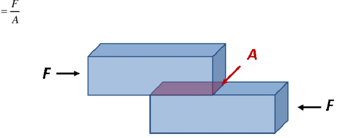
Shear stress is a different type of stress, the force F occurs in shear, as shown in Fig. 2-3. The force here is called the shear force. Dividing the shear force F by the cross-sectional area A, we obtain the shear stress η.
F A
(2.3)
The strain is a normalized measure of deformation representing the displacement from a reference configuration to a current configuration. As with stresses, strains may also be classified as 'normal strain' and 'shear strain' (acting perpendicular to or along the face of an element respectively). As shown in Fig. 2-4, normal strain are X X
X
and Y Y
Y
, and
shear strain are XY X
Y
and YX Y
X
.
Fig. 2-4: Two-dimensional geometric deformation of an infinitesimal material element
In a solid, shear stress is a function of strain, but in a fluid, shear stress is a function of strain rate.
Strain rate is the rate of change in strain with respect to time and is denoted as:
d dt
(2.4)
So it is also the speed at which deformation of an object from its original shape occurs.
2.2.2. Newtonian fluid, Hookean solid and yield stress
A Newtonian fluid is a fluid whose stress versus strain rate is linear and passes through the origin. The constant of proportionality is known as the viscosity. A simple equation to describe a Newtonian fluid behavior is
du dy
(2.5)
Where η is the shear stress exerted by the fluid [Pa] η is the fluid viscosity [Pa·s]
du
dy is the velocity gradient perpendicular to the direction of velocity, or equivalently the
shear rate [s−1]
Fig. 2-5 : Model of a Newtonian fluid, a dashpot
Mathematically, Hooke's law states that
. S .
F k x E x or E
l
(2.6)
Fig. 2-6 : Model of an elastic solid, a spring
Where E is the Young modulus S the section of the sample and l its length
The yield strength or yield point of a material is defined in engineering and materials science as the stress at which a material begins to deform plastically. Prior to the yield point the material will deform elastically and will return to its original shape when the applied stress is removed. Once the yield point is passed, some fraction of the deformation will be permanent and non-reversible.
Fig. 2-7 : Model of a yield stress, a switch
2.2.3. Maxwell model and Kelvin-Voigt Model
Maxwell model describes the dashpot as a Newtonian fluid and models the spring with Hooke's law. It’s a viscoelastic liquid, as show in Fig. 2-8. In this configuration, under an applied axial stress, the total stress and the total strain can be defined as follows, D for dashpot and S for spring:
Total D S
(2.7)
Total D S
(2.8)
Taking the derivative of strain with respect to time, we obtain:
1 Total D S d d d d dt dt dt E dt (2.9) E (2.10)
Fig. 2-8 : Maxwell model, a dashpot and a spring in series
If a Maxwell material is suddenly subjected to a stress ζ0, then the elastic element would
suddenly deform and the viscous element would deform with a constant rate:
t 0 0 t E (2.11)Kelvin Voigt model is represented by a purely viscous dashpot and purely elastic spring connected in parallel as shown in Fig. 2-9 the picture. It’s a model for viscoelastic solid.
Fig. 2-9 : Model of Kelvin-Voigt, a dashpot and a spring in parallel
Since the two components of the model are arranged in parallel, the strains in each component are identical:
Total D S
(2.12)
Similarly, the total stress will be the sum of the stress in each component:
Total D S
(2.13)
From these equations we get that in a Kelvin–Voigt material, the stress ζ, the strain ε and their rates of change with respect to time t are governed by equation:
t E
t d
t dt (2.14)
. The equation can be applied either to the shear stress, in this case the shear modulus G replaces the Yong modulus or to the normal stress of a material.
If we suddenly apply some constant stress ζ0 to a Kelvin–Voigt material, then the deformation
would approach the deformation for the pure elastic material ζ0/E with the difference
decaying exponentially:
0
1 t
t e
Where t is time and λ the rate of relaxation
E
(2.16)
2.2.4. More complex model
There are some more complex models, such as Bingham model, Zener model, and Generalized Maxwell Model.
The Bingham model
Fig. 2-10 : Model of Bingham, a dashpot and a switch in parallel
The Zener Model effectively combines the Maxwell Model and a Hookean spring in parallel. A viscous material is modeled as a spring and a dashpot in series with each other, both of which are in parallel with a spring. For this model, the governing constitutive relation is:
2 1 2 1 2 E d E E dt d dt E E = (2.17)
Fig. 2-11 : Schematic representation of the Zener model
The Generalized Maxwell model also known as the Maxwell–Wiechert model, is the most general form of the linear model for viscoelasticity. It takes into account that the relaxation does not occur at a single time, but as a distribution of times. Due to molecular segments of different lengths with shorter ones contributing less than longer ones, there is a varying time distribution. The Wiechert model takes into account this behavior by having as many spring– dashpot Maxwell elements as necessary to accurately represent the distribution. The figure on the right shows the generalized Wiechert model.
2.3. Magnetic nanoparticles
Magnetic nanoparticles are a class of nanoparticles which can be manipulated using magnetic field. Such particles commonly consist of magnetic elements such as iron, nickel and cobalt and their chemical compounds. While nanoparticles are smaller than 1 micrometer in diameter (typically 5–500 nanometers), the larger microbeads are 0.5–500 micrometer in diameter. The magnetic nanoparticles have been the focus of much research recently because they possess attractive properties, which could see potential use in catalysis(14), biomedicine(15), magnetic resonance imaging, magnetic particle imaging(16), etc.
As described in section 2.1.5 magnetic nanoparticles are used in an experimental cancer treatment called magnetic hyperthermia using the fact that nanoparticles heat when they are placed in an alternative magnetic field is used.
Another potential treatment of cancer includes attaching magnetic nanoparticles to free-floating cancer cells, allowing them to be captured and carried out of the body. The treatment has been tested in the laboratory on mice and will be looked at in survival studies (17).
Magnetic nanoparticles can be used for the detection of cancer. Blood can be inserted onto a microfluidic chip with magnetic nanoparticles in it. These magnetic nanoparticles are trapped inside due to an externally applied magnetic field as the blood is free to flow through. The magnetic nanoparticles are coated with antibodies targeting cancer cells or proteins. The magnetic nanoparticles can be recovered and the attached cancer-associated molecules can be assayed to test for their existence.
Magnetic nanoparticles can be conjugated with carbohydrates and used for detection of bacteria. Iron oxide particles have been used for the detection of Gram negative bacteria like Escherichia coli and for detection of Gram positive bacteria like Streptococcus suis(18).
2.4. Atomic force microscopy (AFM)
Atomic force microscopy (AFM) is a very high-resolution type of scanning probe microscopy, with demonstrated resolution on the order of fractions of a nanometer, more than 1000 times better than the optical diffraction limit. AFM was invented by Gerd Binnig(19) in 1986.
The AFM is one of the foremost tools for imaging, measuring, and manipulating matter at the nanoscale. The information is gathered by "feeling" the surface with a mechanical probe. Piezoelectric elements that facilitate tiny but accurate and precise movements on (electronic) command enable a very precise scanning.
Fig. 2-13: Block diagram of atomic force microscope
2.4.1. Basic principles
The AFM consists of a cantilever with a sharp tip (probe) at its end that is used to scan the specimen surface. The cantilever is typically made of silicon or silicon nitride with a tip radius of curvature of the order of nanometers. When the tip is brought into proximity of a sample surface, forces between the tip and the sample lead to a deflection of the cantilever according to Hooke's law. Depending on the situation, forces that are measured in AFM include mechanical contact force, van der Waals forces, capillary forces, chemical bonding, electrostatic forces, magnetic forces, Casimir forces, solvation forces, etc.
Along with the force, additional quantities may simultaneously be measured through the use of specialized types of probe (see scanning thermal microscopy, scanning joule expansion
microscopy, photothermal microspectroscopy, etc.). Typically, the deflection is measured using a laser spot reflected from the top surface of the cantilever into an array of photodiodes. Other methods that are used include optical interferometry, capacitive sensing or piezoresistive AFM cantilevers. These cantilevers are fabricated with piezoresistive elements that act as a strain gauge. Using a Wheatstone bridge, strain in the AFM cantilever due to deflection can be measured, but this method is not as sensitive as laser deflection or interferometry.
If the tip is scanning the sample at a constant height, a risk would exist that the tip collides with the surface, causing damage. Hence, in most cases a feedback mechanism is employed to adjust the tip-to-sample distance to maintain a constant force between the tip and the sample. Traditionally, the sample is mounted on a piezoelectric tube that can move the sample in the z direction for maintaining a constant force, and in the x and y directions for scanning the sample. Alternatively a 'tripod' configuration of three piezo crystals may be employed, with each responsible for scanning in the x, y and z directions. This eliminates some of the distortion effects seen with a tube scanner. In newer designs, the tip is mounted on a vertical piezo scanner while the sample is being scanned in X and Y using another piezo block. The resulting map of the area z = f(x, y) represents the topography of the sample.
The AFM can be operated in a number of modes, depending on the application. In general, possible imaging modes are contact modes where the tip remains in contact with the sample with a constant deflection of the cantilever and non-contact modes where the cantilever is submitted to a vibration and it is the amplitude of the deflection which is kept constant.
2.4.2. Force spectroscopy
Besides imaging, another major application of AFM is force spectroscopy, the direct measurement of tip-sample interaction forces as a function of the gap between the tip and sample (the result of this measurement is called a force-distance curve).
For this method, the AFM tip is extended towards and retracted from the surface and the deflection of the cantilever is monitored as a function of piezoelectric displacement. These measurements have been used to measure nanoscale contacts, atomic bonding, Van der Waals forces, and Casimir forces, dissolution forces in liquids and single molecule stretching and rupture forces (20). Furthermore, AFM was used to measure, in an aqueous environment, the
dispersion force due to polymer adsorbed on the substrate (21). Forces of the order of a few piconewtons can now be routinely measured with a vertical distance resolution of better than 0.1 nanometers. Force spectroscopy can be performed with either static or dynamic modes. In dynamic modes, information about the cantilever vibration is monitored in addition to the static deflection (22).
Problems with the technique include no direct measurement of the tip-sample separation and the common need for low stiffness cantilevers which tend to 'snap' to the surface. The snap-in can be reduced by measuring in liquids or by using stiffer cantilevers, but in the latter case a more sensitive deflection sensor is needed. By applying a small dither to the tip, the stiffness (force gradient) of the bond can be measured as well(23).
3.
U
SE OF MAGNETIC PARTICLES TO PROBE THE
RHEOLOGY
A way to access the rheological properties of cancer cells is to use magnetic microparticles as probes and to look at their motion in the presence of a magnetic field. In order to check the validity of this approach, we have begun to study the motion of bigger particles, which are easier to follow by optical microscopy and which are well defined relatively to their shape and magnetic properties. We have used known suspending medium, firstly a Newtonian fluid in which we have studied the rotation and translation of a magnetic, this is described in section 3.1. Then we have analyzed the translational motion of probes of different shapes (sphere, needle, plate) inside a gel whose rheological properties were also measured by conventional rheometry; this is described in section 3.2 .
3.1. Motion of a fiber in a Newtonian fluid
3.1.1. Experimental setup
The experimental setup consists essentially of a homemade inverted microscope and a high speed camera (900fps) connected to a special system of ten parallel disks to record the images of the motion of the probe with enough optical resolution. Two coils in Helmholtz configuration are used for applying a constant magnetic field, cf. Fig. 3-1.
Fig. 3-1 : Experimental setup
3.1.2. Rotation
First of all, it’s interesting to discuss the rotation of a magnetic fiber, because compared to a spherical magnetic particle, the magnetic fiber experiences a magnetic torque, due to the shape anisotropy. One issue is to know under which condition the fiber can follow the oscillation of an alternative magnetic field.
Theoretical study
The equation of motion of can be written as(24):
2 2 m h 0 d I dt (3.1)
Where m and h are respectively the magnetic and hydrodynamic torque, is the angle between the magnetic force and the rod.
The moment of inertia I of a rod of length L and mass m, similar to our fiber is given by(25):
2
12 mL
I (3.2)
In a Stokes fluid, the hydrodynamic torque h is always present, and is proportional to the
angular velocity as:
h d dt (3.3)
where the hydrodynamic coefficient α is proportional to the viscosity:
3
3 L C
(3.4)
The factor C, depends on the different models, but is always related to the aspect ratio a
between the length L and the diameter of the fiber D: a L
D
. Fig. 3-2 shows the
hydrodynamic torque as a function of this aspect ratio a for different models. There are no exact analytical solutions and the model rests on different approximations. For Batchelor model(26), in the case of cylinder, we have:
3 2 1.28 ( ) 1.109 2 C (3.5) with:
1 ln 2 a a ,and for a slender body,
( ) 8 C (3.6) with:
1 ln 2 0.5 a a ,For the ellipsoidal Van de Ven model(27):
3 2 ( ) C a a a (3.7)
2
2
2
0 1 1 a dx a x x a x
For the Wilhelm model(28):
1.5 ( ) 2.4 ln 2 C a a a (3.8)
For the Keshoju model(29):
0.15 C (L r ) (3.9) 0 5 10 15 20 0.0 2.0x10⁻¹⁰ 4.0x10⁻¹⁰
Slender Body (Batchelor 1970) Cylinder (Batchelor 1970) (Van de Ven 1989) (C. Wilhelm 2003) (K. Keshoju 2007) H yd ro d yn a m ic to rq u e h Ratio a (length/diameter)
In conclusion, the model of a cylinder represented by Eq.(3.5), which is close to the well known slender body model and also to the model of ellipsoid of Van de Ven, will be the one used for the rest of the study.
Fig. 3-3 : A rod-like fiber in a Newtonian fluid under an alternative magnetic field
The magnetic torque exerted by a magnetic field H on a magnetic moment m is expressed by:
m
m H
(3.10)
The magnetic moment m is the magnetization M time the volume V of the particle:
0
mV M (3.11)
For the magnetization M, we have two simple situations depending on the applied magnetic
field.
1. Case of induced magnetization
If there is no remanent magnetization, the magnetization is a function of the magnetic field as:
H
M H (3.12)
The components of the magnetization on the two directions, parallel and perpendicular to the fiber will be: