HAL Id: hal-00224226
https://hal.archives-ouvertes.fr/hal-00224226
Submitted on 30 Jan 2008
HAL is a multi-disciplinary open access
archive for the deposit and dissemination of
sci-entific research documents, whether they are
pub-lished or not. The documents may come from
teaching and research institutions in France or
abroad, or from public or private research centers.
L’archive ouverte pluridisciplinaire HAL, est
destinée au dépôt et à la diffusion de documents
scientifiques de niveau recherche, publiés ou non,
émanant des établissements d’enseignement et de
recherche français ou étrangers, des laboratoires
publics ou privés.
Blind cooperative diversity using Distributed
Space-Time Coding in Block Fading Channels
Kamel Tourki, Mohamed-Slim Alouini, Luc Deneire
To cite this version:
Kamel Tourki, Mohamed-Slim Alouini, Luc Deneire. Blind cooperative diversity using Distributed
Space-Time Coding in Block Fading Channels. IEEE International Conference on Communications,
May 2008, Beijing, China. pp.1. �hal-00224226�
Blind cooperative diversity using Distributed
Space-Time Coding in Block Fading Channels
Kamel Tourki
Laboratoire I3S CNRS UNSA 2000, rte des Lucioles BP 121 06903 Sophia Antipolis CedexEmail: [email protected]
Mohamed-Slim Alouini
Texas A&M University at QatarEducation city PO Box 23874 Doha, Qatar
Email: [email protected]
Luc Deneire
Laboratoire I3S CNRS UNSA 2000, rte des Lucioles BP 121 06903 Sophia Antipolis Cedex Email: [email protected]
Abstract— Mobile users with single antennas can still take advantage of spatial diversity through cooperative space-time encoded transmission. In this paper, we consider a scheme in which the relay chooses to cooperate only if the source-relay channel is of an acceptable quality and we evaluate the usefulness of relaying when the source acts blindly and ignores the decision of the relay if it may cooperate or not. In our study, we consider a regenerative relay in which the decision to cooperate is based on a signal-to-noise ratio (SNR) threshold and consider the effect of the possible erroneously detected and transmitted data at the relay. We derive the end-to-end bit-error rate (BER) for binary phase-shift keying modulation and look at two power allocation strategies between the source and the relay in order to minimize the end-to-end BER at the destination for a high SNR. Some selected performance results show that computer simulations based results coincide with our analytical results.
I. INTRODUCTION
In many wireless applications, wireless users may not be able to support multiple antennas due to size, complexity, power, or other constraints. The wireless medium brings along its unique challenges such as fading and multiuser interference, which can be mitigated with cooperative diversity [1]–[4]. Emamian and Kaveh proposed the cooperation as solution for combating shadowing [5] and Sendonaris et al. showed that cooperation among users can enlarge the capacity region of an uplink multiuser channel [6]. In traditional cooperative diversity setups, a user is unilaterally designated to act as a relay for the benefit of another one, at least for a given period of time. In certain scenarios, the relay is an actual component of the infrastructure with no own data to be delivered to the network [7]–[11]. Therefore most of these systems use the Decode-and-Forward (DF) or regenerative protocol for cooperation when the relay decodes perfectly the message sent by the source [12]–[14]. Thereby the relay uses feedback to inform the source in order to cooperate, which may be a restrictive condition. We try to overcome these restrictions by using distributed space-time coding (DSTBC) which improves bandwidth efficiency on top of diversity.
A major challenge in distributed cooperative transmissions is to find a way to coordinate the relay transmissions without requiring extra control information (e.g. feedback) overhead, which would reduce part of the gain. The decision to relay can be taken using a cyclic redundancy check (CRC) codes [15]
or using a signal-to-noise ratio (SNR) threshold at the relay as in [16].
We choose DF protocol for communicating in our setup due to the advantages cited in [9] when the relay is near to the source, and we use an SNR threshold to decide if the relay may decode or not. Hence the transmission must be done in two phases. In the first phase, the source communicates its information to the relay. In the second phase and depending on the relay decision, the destination receives from the source and the relay or only from the source. Therefore we consider resource control in the form of power allocation by the source across the two phases.
As expected, the relay may retransmit an erroneously decoded message. Using Alamouti scheme [17], we determine the end-to-end bit error rate (BER) expression for the binary phase shift keying (BPSK) modulation taking the relay error propagation into account. There will be a compromise to strike between the transmit power of the source in the first phase and the decoding threshold SNR at the relay in the second phase.
A. Related Works
Other contributions on selective decode and forward co-operative communication under imperfect regeneration are presented in [16], [18]. In [16], the source broadcasts its message to relay and destination. In the second phase, if the relay has decided to forward, it retransmits its received signal to the destination. This scheme is well known as time repetition coding in which the destination combines the received signal from the source and relay. Otherwise, if the relay has not decided to decode, it remains silent. This induces a rate loss with respect to non cooperative communication because the data is transmitted from different points in space, during different time slots. In [18], the relay is allowed to make errors and the authors opted for DSTC with OFDM for a block fading channel. Therefore they proposed an optimal maximum likelihood (ML) decoder which exploits the knowledge of the error statistics at the relay and a suboptimal decoder when this knowledge is not available.
The remainder of this paper is organized as follows. In sec-tion II, we describe the system model and our proposed blind cooperation mode of opration. In section III the end-to-end BER expression is derived and the optimal power allocation
TABLE I
TRANSMISSION SCHEME IN PHASEII.
T1 T2
source s(n) s(n + 1)
relay (ifγ > γ0) −es∗(n + 1) es∗(n)
and decoding threshold SNR are determined. Finally, some selected simulation results are depicted in section IV while some concluding remarks are given in section V.
II. SYSTEM MODEL
In this section we describe the distributed Alamouti scheme and we note that only one nearby relay is targeted to cooperate. The system model obeys to the topology depicted in Fig. 1 and we restrict our model to three nodes. We assume that each terminal is equipped with one antenna. As depicted in Fig. 1, the transmission is done in two phases, and we must balance the need of resources. The source allocates a power fraction equal toαP for its transmission to the relay in the first phase,
and the remaining power is dedicated to the second phase. We denote hsr, hsd and hrd as the coefficients of the channels between the source (S) and the relay (R), the source and the destination (D) and the relay and the destination, respectively.
(b) PHASE I PHASE II S D R S R D D S R h h hsr sd h sd rd (a)
Fig. 1. Cooperative communication system.
A. Blind cooperation
We describe the proposed transmission protocol which is a time division duplex (TDD) scheme and summarized by Table I. Each frame is subdivided in two consecutive BPSK N-size information symbol blocks s(n) and s(n + 1) to be
trans-mitted in two phases. In the first phase, the source broadcasts
[s(n); s(n + 1)] using only the power fraction αP . Within this
phase, the destination does not consider the received data, but intuitively, we can expect that this power fraction must be as small as possible in order to save more power for the next phase. Therefore in phase I only the relay is assumed to receive the transmitted signal and the N-size signal vectors
yr(i) received are:
yr(i) =
√
αP hsrs(i) + nr(i), i = n, n + 1 (1)
where nr(i) is the additive-noise vector at the relay with a covariance matrix N0IN and we denote γr = αP|hsr|
2
N0 the
received SNR at the relay.
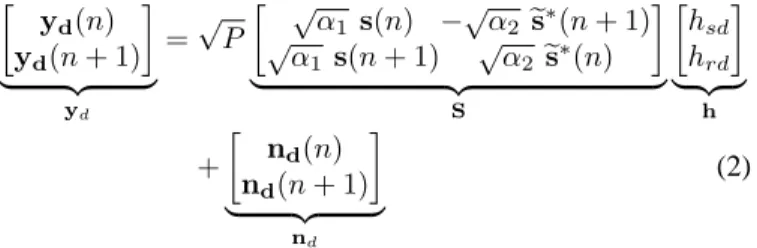
In the second phase, the source retransmits [s(n); s(n + 1)]
using the power fraction α1P . The relay transmission is conditioned by its the received SNRγr; 1) If it exceeds the decoding threshold SNR γ0, the relay decodes the data as
[es(n); es(n + 1)]. Hence in the following block, the relay sends
[−es∗(n + 1); es∗(n)] using the power fraction α
2P and the
destination sees a distributed space-time code as
· yd(n) yd(n + 1) ¸ | {z } yd =√P · √α 1 s(n) −√α2es∗(n + 1) √α 1 s(n + 1) √α2es∗(n) ¸ | {z } S · hsd hrd ¸ | {z } h + · nd(n) nd(n + 1) ¸ | {z } nd (2)
where nd is the additive noise vector at the destination with covariance matrix N0I2N.
Otherwise, 2) ifγr < γ0, the source which ignores the relay decision is sending and D receives
yd(i) =
p
α1P hsds(i) + nd(i), i = n, n + 1 (3)
where nd(i) is the additive-noise vectors at D with a covari-ance matrixN0IN. We note that there is no feedback from the relay to the source which transmits blindly in phase II. But even if the source and the relay are synchronized to transmit, their packets might arrive asynchronous at the destination. We can deal with this problem using the algorithm of [19]. But focusing only on the transmission protocol, we can assume that the signals reach the destination in the same time.
B. Detection procedure
Each transmitting node use a CDMA code which is imple-mented as a training sequence. From a certain codec we can
form two orthogonal codes c1 = [c; c] and c2 = [−c; c]. The source will use c1 and if the relay decide to cooperate, it will use c2. The rank of the code matrix C= [c1 c2] gives us the number of cooperating nodes and the destination will decide which decoding technique to apply.
We can opt for another technique; if the relay decide to cooperate, it transmits a specific bitb = 1 to inform the
desti-nation that it will send. Otherwise, when the destidesti-nation never receives this bit, it supposes that only source is transmitting.
III. PERFORMANCEANALYSIS
In the traditional DF protocol, the relay cooperates only when it decodes perfectly the message. Therefore there is no risk of error propagation by the relay, and in cooperative scheme, the distributed nodes use a space time code as in MIMO systems. But in our scheme, depending on the SNR threshold level γ0, the situation changes because the relay can retransmit an erroneously decoded message. Therefore we need to determine the end-to-end performance of this system which is expressed as
where Pdec is the relay decoding probability, (see Ap-pendix. A) and Pe,d is the probability of error for the direct communication between the source and the destination. In (4),
Pe1 is the error probability at D when S and R cooperate.
Whenγr> γ0, we enumerate these cases:
• The relay decodes with errors the received message, and this event has a probability of Ps,r
e .
• The relay decodes perfectly the received message with probability of 1 − Pes,r.
Therefore P1
e is derived as
Pe1= 0.5 × Pes,r+ (1 − Pes,r)Pe2 (5)
where P2
e is the error probability for the 2 by 1 Alamouti scheme which depends on the network architecture, and 0.5 is the largest error probability when the Alamouti scheme orthogonality is broken. Ps,r
e is derived as (see Appendix. B for the proof):
Ps,r e =aQ( p bγ0) − a exp µγ 0 γ ¶ s 1 1 + 2 bγ ×Q Ãs 2γ0 µ b 2 + 1 γ ¶! (6) whereQ(.) is the Marcum Q-function, a and b depend on the
modulation.
A. Parameter optimization
The most important parameters which control the proposed scheme are the power fraction α and the decoding threshold
SNR at the relay γ0. Both parameters must be chosen to satisfy:
(αm, γ0m) = arg min Pe,sys (7)
where α ∈]0, 1[ and γ0 ∈ R. Given the complicated form of
Pe,sys, it is evident that this optimization can not be conducted analytically in a straightforward fashion. Therefore we will look in what follows for the optimum parameters based on some numerical results.
IV. SIMULATION RESULTS
A. Network Geometry
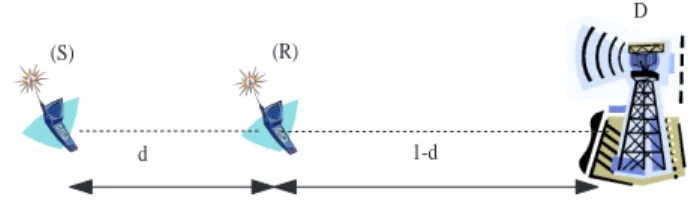
We anticipate that cooperation will perform differently as function of the positions of the users with respect to desti-nation. Hence we study two different network geometries, de-noted by symmetric network (SN) (see Fig. 1) and asymmetric or linear network (LN) (see Fig. 2). In the linear (LN) case, we model the path-loss, i.e. the mean channel powers σ2
h, as a function of the relative relay position r by
σ2sd= 1 , σsr2 = d−ν , σ2rd= (1 − d)−ν (8)
where ν is the path loss exponent and 0 < d = dsr < 1. The distances are normalized by the distance dsd. In these coordinates, the source can be located at (0,0), the destination can be located at (1,0), without loss of generality, and the relay is located at (d,0) [20]. In the symmetric network (SN), hsd
d 1-d
D (R)
(S)
Fig. 2. Asymmetric (or linear) network.
andhrdare drawn with same unit-variance (equal sub channel gains), but considering source and relay are close together, we
setσsr2 = 16.
B. Simulation Results
In this section, we evaluate the performance of our scheme in terms of end-to-end BER at the destination as function of
SNR = P/N0 for a BPSK modulation. We report results
for ν = 4, a block length N = 50, and we model all
channels as Rayleigh block flat fading with additive white Gaussian noise. Figs. 3-5 show the end-to-end performance of our scheme with optimized power allocation, compared with the non cooperative system and MISO system respectively. In order to make a fair comparison between different schemes, we enforce all systems to transmit with the same overall power. As mentioned before,P2
e depends on the network architecture.
a) Equal sub-channel gains (SN): For equal sub-channel
gains γ, the moment generating function (MGF) of the
in-stantaneously experienced SNRρ for a system with t transmit
antennas,r receive antennas and λ is the channel energy, can
be expressed as [21]
φρ(s) =
1
(1 − ρ × s)u (9)
whereR is the transmission rate, u = t × r and
ρ = 1 R λ t S N = λ t Es N0 = log2(M ) λ t P N0 (10) whereEsis the energy per symbol,P the energy per bit and
M = 2 for BPSK modulation. We considered BPSK Alamouti
scheme thereforeR = 1, N = N0 and NS = NP0. The analysis in [13], [14], [22] allows us to express the BER for BPSK modulation in closed form as
Pt,r(R, γ, S N) = φR1λtNS(−1) · 1 2√π Γ(u + 1/2) Γ(u + 1) ¸ × 2F1 µ u, 1/2; u + 1; (1 + 1 R γ t S N) −1 ¶ (11) where 2F1(a, b; c; x) is the Gauss hypergeometric function with 2 parameters of type 1 and 1 parameter of type 2.
b) Unequal Sub-Channel Gains (LN): For unequal
sub-channel gains, the MGF cam be shown to be given by
φ1 R λ t S N(s) = u X i=1 Ki φ1 Rλit NS(s) (12)
TABLE II
OPTIMIZED PARAMETERS AT HIGHSNR (30 dB).
System SN LN, d = 0.1 LN, d = 0.5
αm 0.227 0.017 0.44
γ0m 6.57 6.78 6.28
with constants Ki [13], [23] (See appendix C)
Ki = u Y i′=1,i′6=i ¯ γi ¯ γi− ¯γi′ (13)
where γ¯i is the average channel gain of the ith path. This allows us to derive the expression of BER in closed form where all the channel gains differ. The error rate can be expressed as Pucg(u)(e) = u X i=1 KiPt,r µ R, ¯γi, S N ¶ (14)
1) Equal transmit power in phase II: We set α1 = α2 =
(1 − α) /2 1, and we determine the optimum variables in
Eq. (7) at high SNR. We consider an overall transmit power
P . Thereby, we must have α + α1+ α2 = 1. But with a
blind source behavior, we note that the overall power will be less than P when the relay decide to not cooperate because
α2 = 0. The parameter optimization results for the SN and
LN architectures are derived numerically at a high SNR and are collected in Table. II.
In the symmetric network, Fig. 3 shows that our scheme achieves full diversity and the influence of the distributed STBC with optimized parameters (αm, γ0m) = (0.227, 6.57) is small (2 dB) wrt the MISO system in which each antenna transmits with a power equal to P/2. But the full diversity
order performance will be saved for some appropriate varia-tions on the parameters when we choose (0.1, 8). When we
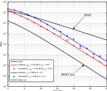
take a lower threshold SNR level γ0 = 0 dB, we observe a little enhancement in the end-to-end performance for a low SNR, but we loose the full diversity order. Fig. 4 and 5 show the simulation results for a linear network when the relay is located between the source and the destination at (0.1,0) and (0.5,0) respectively. The gains due to the optimized power allocation in the cooperation are clearly more significant when the relay is close to the source (d = 0.1). At this situation,
it is clear that our scheme never performs worse than a non cooperative scheme. Thereby, our results confirm the fact that the DF protocol maximizes the capacity when the relay is near to the source [9]. We note that the influence of the distributed STBC with optimized parameters is more significant than the SN case, and it is interesting to note that all simulation results are in agreement with our analysis-based results.
2) Unequal transmit power in phase II: Dividing the
remaining power for the second phase between the source and the relay, the power fraction (1 − α) P/2 will be lost if the relay decides to not cooperate. In order to overcome
1α
1andα2can be optimized based on channel gains of the links between S and D, and between R and D.
0 5 10 15 20 25 30 10−7 10−6 10−5 10−4 10−3 10−2 10−1 100 SNR [dB] BER SISO Analysis, γ0m = 6.57 dB & αm = 0.227 simulations, γ0m = 6.57 dB & αm = 0.227 Analysis, γ0 = 8 dB & α = 0.1 simulations, γ0 = 8 dB & α = 0.1 Analysis, γ0 = 0 dB & α = 0.1 simulations, γ0 = 0 dB & α = 0.1 MISO 2x1 SISO MISO 2x1
Fig. 3. Performance results of the symmetric network (SN) when the source and the relay use the same transmit powerα1= α2= (1 − α) /2.
this unbalanced allocation, we take another power allocation strategy for which the source and the relay have independent power constraints. In the second phase, the source and the relay transmit with respective power fractions2
½
α1= (1 − α)
α2= 1, if γr≥ γ0 (15)
In the symmetric network, Fig. 6 shows that our scheme achieves full diversity and the influence of the distributed STBC with optimized parameters (αm, γ0m) = (0.413, 6.92) is small with respect to the MISO system in which, each antenna transmits with a power equal to P . In this case,
we note that the DSTC is never performs worse than non cooperative system (SISO), because for all SNR levels, the system uses at least a transmit powerP as the non cooperative
system.
V. CONCLUSIONS
In this work, we studied the performance of a blind coopera-tion using a distributed STBC scheme, and we have shown that a minimized end-to-end BER is reached if the relay position is well chosen. If the relay is sufficiently near to the source, more power is saved to transmit the data from the source to the relay, and the error at the relay detector can be minimized with an appropriate choice of a predetermined cut-off threshold
γ0. Also we can note that with a closer relay we reduce the synchronization problem at the destination.
APPENDIX
In this appendix, we collect all the proofs.
2The source and relay may have different power constraintsP
SandPR wherePR< PS.
0 5 10 15 20 25 30 10−8 10−7 10−6 10−5 10−4 10−3 10−2 10−1 100 SNR [dB] BER SISO Analysis, γ0m = 6.78 dB & αm = 0.017 simulations, γ0m = 6.78 dB & αm = 0.017 Analysis, γ0 = 8 dB & α = 0.1 simulations, γ 0 = 8 dB & α = 0.1 Analysis, γ0 = 0 dB & α = 0.1 simulations, γ0 = 0 dB & α = 0.1 MISO 2x1 SISO MISO 2x1
Fig. 4. Performance results of the linear network (LN), where the relay is near to the source (d = 0.1) and both transmitting with the same power
(1 − α) /2.
A. Decoding probability
We consider the probability that the relay decodes the signal transmitted by the source. The relay decodes if its received
SNR γ is larger than the chosen SNR threshold γ0.
Pdec = P (γ > γ0) (16)
The instantaneous SNR is determined by the fading channel power|hsr|2, the power fractionα allocated to the first phase, and the average SNR. Therefore,
Pdec = Z ∞ γ0 α.Γ 1 σ2 sr exp(− t σ2 sr )dt = exp(− γ0 σ2 srαΓ ) (17) whereΓ = P N0.
B. Probability of Error at a decoding Relay
We consider a special case of communication over a Rayleigh flat-fading channel where detection is performed only when the instantaneous SNR exceeds a thresholdγ0. The resulting pdf of the effective SNR is a clipped exponential function : p(γ0) γ (γ) = ( 0 γ < γ0 1 c 1 γexp ³ −γγ ´ γ ≥ γ0 (18) where γ is the mean SNR of the Rayleigh fading channel,
andc = exp(−γ0/γ) is a normalizing constant ensuring unit
area under the pdf. In the following, we determine the error probability for BPSK, which is given by
Ps,r e = Z Pe(γ)pγ(γ)dγ = Z γb γa aQ(pbγ)pγ(γ)dγ (19) 0 5 10 15 20 25 30 10−8 10−7 10−6 10−5 10−4 10−3 10−2 10−1 100 SNR [dB] BER SISO Analysis, γ 0m = 6.28 dB & αm = 0.44 simulations, γ0m = 6.28 dB & αm = 0.44 Analysis, γ0 = 8 dB & α = 0.1 simulations, γ0 = 8 dB & α = 0.1 MISO 2x1 MISO 2x1 SISO
Fig. 5. Performance results of the linear system, where the relay is halfway between the source and the destination (d = 0.5). Both use an equal transmitting power. 0 5 10 15 20 25 30 10−7 10−6 10−5 10−4 10−3 10−2 10−1 100 SNR in (dB) BER SISO Analysis, γ0m = 6.92 dB & αm = 0.413 simulations, γ0m = 6.92 dB & αm = 0.413 Analysis, γ0 = 8 dB & α = 0.1 simulations, γ0 = 8 dB & α = 0.1 Analysis, γ0 = 0 dB & α = 0.1 simulations, γ0 = 0 dB & α = 0.1 MISO 2x1 SISO MISO 2x1
Fig. 6. Performance results of the symmetric network (SN) when the source allocates a transmit powerα P in phase I and the remaining power in the
second phase while the relay transmits with a power equal toP .
wherea = 1, b = 2 and Q(pbγ)= Z ∞ √ bγ 1 √ 2πexp µ −t 2 2 ¶ dt =1 − Z √ bγ 0 1 √ 2πexp µ −t 2 2 ¶ dt (20) Introducing u(γ) = Z pγ(γ)dγ (21)
we obtain by partial integration of (19)
Ps,r e = h u(γ)aQ(pbγ)iγb γa − Z γb γa d dγ ³ aQ(pbγ)´u(γ)dγ (22)
Following the Leibnitz’s rule for differentiation of integrals ∂ ∂x Z g(x) f(x) F (x, x′)dx′=F (x, g(x))∂g(x) ∂x − F (x, f(x)) ∂f (x) ∂x + Z g(x) f(x) ∂ ∂xF (x, x ′)dx′ (23) With x′= t x = γ g(γ) =√bγ f (γ) = 0 (24) (22) can be re-written as Ps,r e = h u(γ)aQ(pbγ)iγb γa + a √ b 2√2π Z γb γa 1 √ γexp(− b 2γ)dγ (25) However note that the pdf range is γa = γ0 and γb → ∞. Substituting these limits in (25) and making the change of
variable µ b 2 + 1 γ ¶ γ = t 2 2 (26)
we obtain the desired result given in (6).
C. Derivation of the Constants Ki We prove in this appendix that
Ki = u Y i′=1,i′6=i γi γi− γi′ (27) Without loss of generality, K1 is derived here. The fractional expansion is equated to the product expression, i.e.
u X i′=1 Ki′ 1 − γi′s ≡ u Y i′=1 1 1 − γi′s (28) To obtain K1, (28) is multiplied by(1 − γ1s) giving
(1−γ1s) u X i′=1 Ki′ 1 − γi′s ≡ (1−γ 1s) u Y i′=1 1 1 − γi′s (29) after which s is set to s = 1/γ1 yielding
K1= u Y i′=2 1 1 −γi′ γ1 = u Y i′=2 γ1 γ1− γi′ (30) The same procedure is repeated for anyKi in order to derive (27).
REFERENCES
[1] J. N. Laneman, D. N. Tse, and G. W. Wornell, “Cooperative diversity in wireless networks: Efficient protocols and outage behavior,” IEEE Trans. Inform. Theory, vol. 50, no. 12, pp. 3062–3080, Dec. 2004. [2] A. Sendonaris, E. Erkip, and B. Aazhang, “User cooperation diversity,
part i:system description,” IEEE Trans. Comm., vol. 51, no. 11, pp. 1927–1938, Nov. 2003.
[3] ——, “User cooperation diversity, part ii:implementation aspects and performance analysis,” IEEE Trans. Comm., vol. 51, no. 11, pp. 1939– 1948, Nov. 2003.
[4] T. M. Cover and C. S. K. Leung, “An achievable rate region for the multiple-access channel with feedback,” IEEE Transactions on Informations Theory, vol. IT-27, no. 3, pp. 292–298, May 1981.
[5] V. Emamian and M. Kaveh, “Combating shadowing effects for systems with transmitter diversity by using collaboration among mobile users,” in Proc. Int. Symp. Communications, Taipei, Taiwan, Nov. 2001. [6] A. Sendonaris, E. Erkip, and B. Aazhang, “Increasing uplink capacity
via user cooperation diversity,” in Proc. Int. Symp. Information Theory, Cambridge, MA, Aug. 1998.
[7] T. M. Cover and A. A. E. Gamal, “Capacity theorems for relay channel,” IEEE Transactions on Informations Theory, vol. IT-25, no. 5, pp. 572– 584, September 1979.
[8] M. O. Hasna and M. S. Alouini, “End-to-end performance of transmis-sion systems with relays over rayleigh-fading channels,” IEEE Transac-tions on Wireless CommunicaTransac-tions, vol. 2, no. 6, pp. 1126–1131, Nov. 2003.
[9] C. T. K. Ng and A. J. Goldsmith, “Capacity and power allocation for transmitter and receiver cooperation in fading channels,” in Proc. IEEE International Conference on Communications.(ICC), Istanbul, Turkey, June 2006.
[10] P. A. Anghel, G. Leus, and M. Kaveh, “Distributed space-time cooper-ative systems with regenercooper-ative relays,” IEEE Transactions on Wireless Communications, vol. 5, no. 11, pp. 3130–3140, Nov. 2006.
[11] C. T. K. Ng, N. Jindal, A. J. Goldsmith, and U. Mitra, “Capacity gain from two-transmitter and two-receiver cooperation,” IEEE Transactions on Information Theory, 2007, to be published.
[12] J. N. Laneman and G. W. Wornell, “Distributed space-time-coded protocols for exploiting cooperative diversity in wireless networks,” IEEE Trans. Inform. Theory, vol. 49, no. 10, pp. 2415–2425, Oct. 2003. [13] M. Dohler, “Virtual antenna arrays,” Ph.D. dissertation, University of
London, United Kingdom, 2004.
[14] K. Tourki and L. Deneire, “End-to-end performance analysis of two-hop asynchronous cooperative diversity,” in 49th annual IEEE Global Telecommunications Conference, San Francisco, California, USA, Nov. 2006.
[15] T. E. Hunter, S. Sanayei, and A. Nosratinia, “Outage analysis of coded cooperation,” IEEE Transactions on Information Theory, vol. 52, no. 2, pp. 375–391, February 2006.
[16] P. Herhold, E.Zimmermann, and G. Fettweis, “A simple cooperative extension to wireless relaying,” in Proc Int. Zurich Seminar on Com-mun.(IZS), pp. 3639., Zurich, Switzerland, 2004.
[17] S. M. Alamouti, “A simple transmit diversity technique for wireless communications,” IEEE Journal on Select Areas in Communcations, vol. 16, no. 8, pp. 1451–1458, Oct. 1998.
[18] G. Scutari and S. Barbarossa, “Distributed space-time coding for re-generative relay networks,” IEEE Transactions on Wireless Communi-cations, vol. 4, no. 5, pp. 2387–2399, Sep. 2005.
[19] K. Tourki and L. Deneire, “Channel and delay estimation algorithm for asynchronous cooperative diversity,” Springer’s International Journal Wireless Personal Communications : Special Issue on Elective Topics towards Vision to Reality of the Wireless Future, vol. 37, no. 3-4, pp. 361–369, May 2006, invited paper.
[20] J. N. Laneman and G. W. Wornell, “Energy-efficient antenna sharing and relaying for wireless networks,” in Proc. IEEE Wireless comm. and Networking Conf. (WCNC), Chicago, IL, USA, Sep. 2000.
[21] K. S. Marvin and M. S. Alouini., Digital Communication over Fading
Channels, A Unified Approach to Performance Analysis. Wiley Series
in Telecommunications and Signal Processing, 2000.
[22] H. Shin and J. H. Lee, “”Exact Symbol Error Probability of Orthogonal Space-Time Block Codes”,” in Proc. of the IEEE Global Telecommuni-cations Conference., Taipei, Taiwan, Nov. 2002.
[23] K. Tourki and L. Deneire, “”Channel And Delay Estimation Algorithm For Asynchronous Cooperative Diversity”,” in The 9th International Symposium on Wireless Personal Multimedia Communications, San Diego, CA, USA, Sep. 2006.