ISSN 1392 - 1207. MECHANIKA. 2013 Volume 19(1): 81-86
Methods of the rational choice of a labyrinth seal design for gas
pumping units
А. Bellaouar*, B.V. Kopey**, N. Abdelbaki***
*Ivano-Frankivsk National Technical University of Oil and Gas, Karpatska str., 15, 76019 Ivano-Frankivsk, Ukraine, E-mail: bellaouar_abd@yahoo.fr
**Ivano-Frankivsk National Technical University of Oil and Gas, Karpatska str., 15, 76019 Ivano-Frankivsk, Ukraine, E-mail: kopeyb@nung.edu.ua
***Faculty of Hydrocarbons and Chemistry, University M’hamed Bouggara, Independence Avenue, 35000 Boumerdes, Algeria, E-mail: lfep@umbb.dz
http://dx.doi.org/10.5755/j01.mech.19.1.3611
1. Introduction
Modern technology is characterized by a tendency to apply the ultra-high pressure and temperature in manu-facturing and energy sectors. With the increasing paramet-ric options of the working body of turbomachinery the research questions and rational design of the labyrinth seals are becoming more relevan, since an increase in ini-tial pressure increases the leakages through all the laby-rinth seals of the machine and reduces the benefits of working medium with high parameters [1]. It is therefore very great interest in providing the theoretical and experi-mental study of labyrinths.
Development of the theory of labyrinth seals is supported by numerous experimental studies, since the general pattern of resistance between the seal and its de-sign has not been established and couldn’t be found with the required accuracy by the analytical way. The use of computer systems of finite-element analysis for the design of machines and their parts is very relevant today. After all, these systems quickly and efficiently solve complex problems of mathematical physics, whose solution is diffi-cult to obtain in analytical form. Experimental study of seal is both through the study of the influence of various geometric and operational factors on the flow rate, and through the study of distribution of pressures and velocities in the sealing elements [2].
In this work we consider the problem of deve-lopment of parametric finite-element models of labyrinth seals for gas pumping units (GPU) in a system of finite element analysis Cosmos FloWorks for SolidWorks. The focus was oriented on the fact that for large-scale study and optimization of labyrinth seals its finite element model should be parametric, that is suitable for easy modification of any of its parameter. Therefore, to build the model the program of popular object-oriented language called VBA is used for, which communicates with the SolidWorks by interface programming (Application Programming Inter-face of SolidWorks). The authors consistently and thor-oughly explained the methods of design improving of a labyrinth seal after the construction of its axisymmetric model.
Labyrinth seals - one of the most important types of seals in the cooling system, lubrication, etc., can take to improve efficiency of GPU by minimizing the parasitic leakage and overflow of air, gas and oil in compressors, turbines and blowers [3].
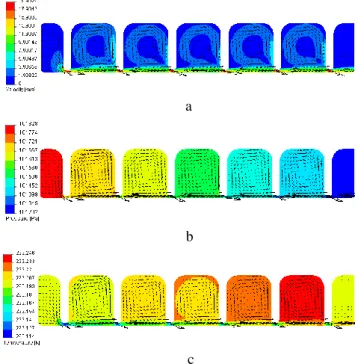
The main reason of failure is the destruction of the labyrinth seal feathers, wear or contamination of grooves. The sealing mechanism of the labyrinth seals is repeated by throttling the working environment [4], which flows through the chambers and narrow clearances with sharply varying throat area. In a shrinking part of the slit there is an adiabatic efflux, accompanied by an increase in speed as well as pressure drop and flow temperature. In the cell the gas velocity decreases and this is accompanied by the dissipation of kinetic energy of flux. The temperature is restored to its original value. In the subsequent narrowing and cameras the process is repeated with the only differ-ence being that due to a diminished flux rate, as well as pressure drop and temperature rise under the crest (Figs. 1 and 2).
a
b
c
Fig. 1 Changes in the physical parameters of gas labyrinth seals: a – speed, m/s; b - pressure, Pa; c - tempera-ture, K
Hydrodynamic characteristics of labyrinth seals depend significantly on the flow regime of fluid in the gap. There are laminar and turbulent regimes, the difference in the nature of fluid flow in which leads to a difference in the laws of resistance to flow.
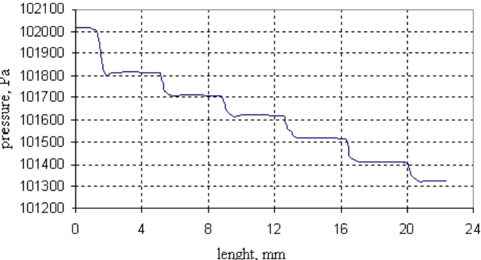
Fig. 2 Changes in the pressure under the crest on the length of the labyrinth seal
2. Development of finite-element model of the labyrinth seal
Authors proposed a method of the configuration
of the labyrinth seal modernization by optimizing the basic geometrical parameters of a simple labyrinth seal and the erection of additional barriers to the movement of the working environment to reduce the overflow of the wor-king environment through it. To improve the design the finite-element model of the gas flow in the canals of the labyrinth was used. Finite element method is to divide the body into a finite number of small items mainly in the form of triangles or squares for the plane problem and the poly-hedra for the spatial problem and solving systems of linear equations.
With SolidWorks CAD systems consisting of el-ements [5] we established a parametric three-dimensional computer model of the labyrinth seal, easy to design im-provements that makes it possible to modify the individual geometric parameters, as well as to determine the influence of individual parameters (Table 1 and Fig. 3) on the char-acteristics of labyrinth seal.
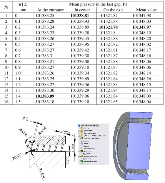
Fig. 3 The design of a labyrinth seal with the geometrical parameters optimization
Table 1 Model parameters
№ Parameter Symbol Name in 3D model First and last value, step
1 Chamber radius R1.R2
(R12)
D1@sketch1
D7@sketch1 from 0 tо 1.5 mm step 0.1 mm 2 Radii of the rounded edge of the sealing ridge
(to the side of high pressure) Rv1 D16@sketch1 from 0 tо 0.689 mm step 0.1 mm 3 Radii of the rounded edge of the sealing ridge
(to the side of low pressure) Rv2 D17@sketch1 from 0 tо 0.689 mm step 0.1 mm 4 Radii of the two side rounded edge of the
sealing ridge Rv1.Rv2 (Rv12) D16@sketch1 + D17@sketch1 from 0 tо 0.3445 (0.689/2) mm step 0.1 mm
5 Slope of feather Asl D8@sketch1 from 90 to 70 step 5
The limits of admissible values were chosen from the condition of the possibility of constructing a model in accordance with the limits of the parameters of existing structures. To automate the adjustment model a computer program in VBA was developed, which interacts with the SolidWorks using the programming interface for Solid-Works (Application Programming Interface). Using it you can easily modify model parameters from an initial value to the final with a given step.
For the calculation of the working medium flow-ing through the labyrinth seals and the loss of pressure in
them when the amount of clearance is widely used by well-known formula Stodola [6, 7], based on the concept of complete extinction rate of the cells and the absence of flow restriction in the gaps, likens the serial number of nozzles: 2 2 0 0 0 p p G f zp v , (1)
area of an annular gap δ with a diameter d; z is the number of gaps in the seal; p0 and ν0 is the pressure and specific volume of the medium before sealing; p is medium pres-sure in the last gap.
This formula is sufficient to calculate, and it can be used to compare the relative efficiency of the different design variations of labyrinth seals in the process of certain geometrical parameters changing. In our case, the geomet-rical parameters of the formula Stodola not change; there-fore, in determining the leakage through the labyrinth we take into account only the pressure of the medium in the last gap. Note that as of this magnitude, we suggested to the arithmetic mean of the values of pressure, measured at all points of the height of the last gap (Y coordinates) at the entrance, in the centre and at the end of the last ridge.
Baseline data of the problem of computer gashydrodynamics is the following:
the type of problem - a two-dimensional axisymmet-ric;
the main settlement option (optimization criterion) - the average pressure in the last gap;
software of computer simulation - Cosmos FloWorks 2009 for SolidWorks 2009;
a network of finite elements - the optimum size and arrangement of cells;
geometry of the computational domain - Fig. 3;
boundary conditions:
− velocity of the gas inlet chamber – 1 m/s
− the pressure at the outlet of the chamber –
101325 Pa;
operating environment - methane gas.
Computation time of one version of the model - about 40 minutes.
In order to obtain the most accurate result, the pressure in the last gap equals the average arithmetic pres-sure values obtained at all points of the height of the gap at the entrance in the center and at the end of the last ridge.
3. The choice of rational parameters of labyrinth seal
Improving the design of a labyrinth seal for GPU is to develop products with the desired configuration of the ridge and the camera, ensuring minimal leakage of gas in the last gap. The geometric labyrinth seal affecting these characteristics include the chamber radius of the labyrinth seal (R1, 2), the radii of the rounded edge of the sealing ridge (Rv1. Rv2) and its slope (Asl) (Table 1).
It is known that a math problem of optimization and improvement is to find the extremum (minimum or maximum) of a real function in a certain region. There are many methods of multivariate optimization transitions: direct (exhaustive search, Gauss, Gauss-Seidel), the first
order (gradient) second-order (Newton-Raphson), stochas-tic (Monte Carlo, genestochas-tic algorithms). For the decrease in the number of calculations of finite-element models one can use the methods of planning experiments, finding the optimal parameters [8].
The authors have chosen the Gauss-Seidel itera-tion, as the most obvious and simple [9]. According to this method of search – experience to move to the area of ex-treme implemented by alternately variation of independent variables. It is assumed that all other factors remain at this time non-modified (fixed). We choose the base point 1 (x01, x02,…, x0n), where n number of managed input vari-ables. Then we select the level of variation of independent variables. The low speed of calculation in this casemain drawback of this method is immaterial, since there are a small number of independent variables, and the choice of a very high level can lead to gross errors in finding the ex-tremum.
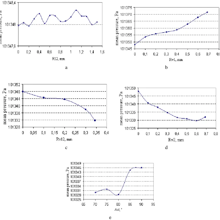
Application of the mentioned method to have de-signed the labyrinth involves the selection of the first re-ference point on the level of R1 = R2 = Rv1 = Rv2 = 0, Asl = 90 to change the value of one independent variable from the initial to the boundary with the selected step (Ta-ble 1), the values of the other varia(Ta-bles are fixed at the same time. At radius of the first stage of change the first independent variables the labyrinth seal (R1 and R2 at the same time (R12)) from 0.01 to 1.5 mm in 0.1 mm, while the other variables were equal to the original. The results of the changes in the average pressure in the last gap on the value of this parameter are shown in Fig. 4, a.
Further we fixed R12 = 0.2 mm (the optimum value obtained in the first step of the experiment) and changed Rv1, leaving all other variables equal to the source (Fig. 4, b). As we see, increasing the radius of rounding the input edge sealing ridge increases the pressure in the gap. In the third stage, fixing the value of R12 = 0.2 mm and Rv1 = 0 mm at baseline Asl, we changed Rv2 (Fig. 4, c).
Analysis of the literature on the development of the labyrinth seal and the refined theory for the calculation of leakage protection through the labyrinth seal shown that there are still options for a labyrinth seal with a rounded front edge of the sealing ridge is therefore necessary to examine the option, in which the front edge is rounded to the output simultaneously with its edge. For this fixed value of R12 = 0.2 mm and varied Rv1 and Rv2 simultane-ously (Rv12) at baseline Asl (Fig. 4, d).
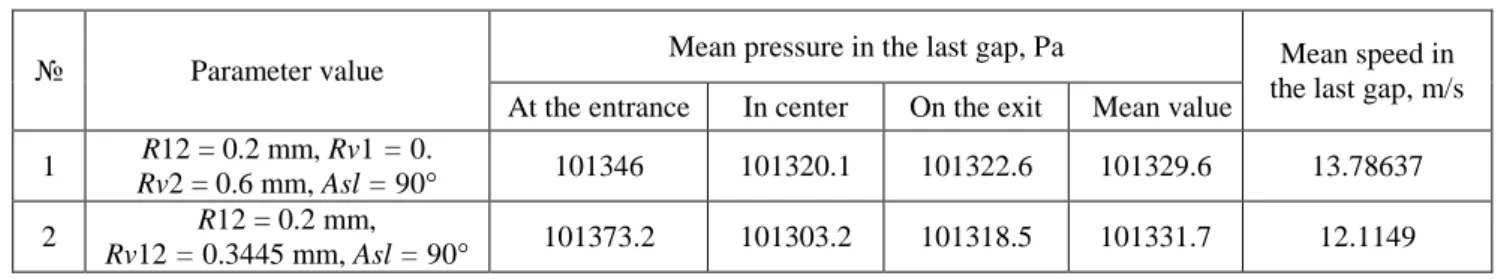
Comparing this version with the preceding shows that the average pressure in the last gap of the labyrinth seal in the first variant (R12 = 0.2 mm, Rv1 = 0, Rv2 = 0.6 mm) is slightly smaller than the second (R12 = 0.2 mm, Rv12 = 0.3445 mm) more, so choosing the best option should be analyzed vat findings, see Table 2.
Table 2 The dependence of the average pressure and velocity in the last gap on the geometric parameters labyrinth seal
№ Parameter value Mean pressure in the last gap, Pа Mean speed in
the last gap, m/s At the entrance In center On the exit Mean value
1 R12 = 0.2 mm, Rv1 = 0.
Rv2 = 0.6 mm, Asl = 90° 101346 101320.1 101322.6 101329.6 13.78637
2 R12 = 0.2 mm,
Analysis (see Table 2) showed that the pressure at the inlet to the gap of the last ridge in the first version is less than the second, while the speed in the middle of the gap height is higher. Across the center of the crest of the pressure in the second version is smaller than the first, however, closer to the shaft, this difference decreases and the speed is almost identical, except for a few points closer to the ridge. Pressure on the outlet of the last ridge in the first version is much less than the pressure in the second option, and speed in both versions is the same.
As you can see, it is difficult to make an unam-biguous choice in favor of certain variant, you can use both if Asl = 90, but with the option when the crest has a bias towards the front edge, the gap width increases, while decreasing the average pressure in the last gap [10], so the first option considered the best and we select it.
Finally we complete the search for the optimal variant by the change of angle of the ridge Asl with step of
5° for the first variant (Fig. 4, e).
Can be seen from the dependence curve of the average pressure in the last gap on radius of the labyrinth chamber R12 (Fig. 4, a) that changes the value of the pres-sure is not constant, there are also some convergence in the results, for example, a value 0, 0.2, 1.4 of R12, this ex-plains the labyrinth chamber radius impact on the pressure and reduces the flow rate and creates less resistance to the movement of gas. As example the Table 3 present calcula-tion by the software of computer simulacalcula-tion Cosmos FloWorks for Fig. 4, a.
Using these results (Fig. 4) we can choose the necessary parameters of labyrinth seals, depending on the conditions of his work. Design with the basic geometric parameters: R1 = 0.2 mm, R2 = 0.2 mm, Rv1 = 0 mm, Rv2 = 0.6 mm, Asl = 80 as shown in Fig. 5 is rational.
a
b
c
d
e
Fig. 4 Dependence of the average pressure in the last gap on the geometric parameters: a - radius of the chamber of the labyrinth; b - radius of the rounded front edge of the sealing ridge; c- radius of rounding off the edge of the sealing ridge; d - the radii of rounding the edge sealing ridge on both sides; e - angle of the ridge
Table 3 The dependence of the average pressure in the last gap on the radius of the chamber of the labyrinth (R1, R2)
№ R12, mm Mean pressure in the last gap, Pа
At the entrance In center On the exit Mean value
1 0 101383.25 101338.81 101321.87 101347.98 2 0.1 101383.28 101338.93 101321.88 101348.03 3 0.2 101383.24 101338.89 101321.78 101347.97 4 0.3 101383.23 101339.28 101321.8 101348.10 5 0.4 101383.26 101339.45 101321.88 101348.20 6 0.5 101383.27 101338.95 101321.82 101348.02 7 0.6 101383.27 101339.42 101321.81 101348.17 8 0.7 101383.3 101339.30 101321.87 101348.16 9 0.8 101383.21 101339.08 101321.88 101348.06 10 0.9 101383.27 101339.10 101321.83 101348.06 11 1.0 101383.26 101339.34 101321.82 101348.14 12 1.1 101383.25 101339.69 101321.84 101348.26 13 1.2 101383.27 101339.36 101321.83 101348.15 14 1.3 101383.30 101339.29 101321.84 101348.14 15 1.4 101383.09 101339.06 101321.84 101348.00 16 1.5 101383.18 101339.10 101321.85 101348.04
Fig. 5 Rational design of labyrinth seal
4. Conclusions
It has been established that the slope of the ridge in the direction of greater pressure, the radius of rounding off the edge of the ridge and the radius of the chamber, substantially affect the pressure in the chamber and in the gap.
The increasing the radius of the rounding only for the input edge of the crest of the labyrinth seal is insignifi-cant for decreases the pressure in the last gap and the vo-lume of gas flowing out of the labyrinth seal. Rounding, made on both sides of the crest of the labyrinth with a maximum size of radius - 0.3445 mm (0.689/2) at 90 more influence on overflow the gas. The radius of roun-ding off the edge of the sealing only the crest of 0.6 mm provides a smaller overflow of gas from the labyrinth seal. Reducing the angle of inclination of the crest of a labyrinth seal from 90 to 80 with a given radius significantly re-duces the pressure in the last gap resulting in minimizing the overflow of gas from the labyrinth seal.
Proposed by the authors advanced design of a simple labyrinth seal substantially reduces the overflow of the working environment through it, and in it turn, greatly
increases the efficiency and effectiveness of operation of GPU. In addition the manufacturing of an advanced design of the labyrinth seals requires less material.
With complex software SolidWorks - Cos-mosFloWorks 2009 and the three-dimensional parametric Delhi, a labyrinth seal offers a technique to improve its geometry. The developed method is practical and can be used to analyze and optimize any GPU assemblies in the system of SolidWorks.
References
1. Hsu, Y.; Brennen, C.E. 2002. Fluid flow equations for rotordynamic flows in seals and leakage paths, Fluids Engineering 124: 176-181.
http://dx.doi.org/10.1115/1.1436093.
2. Schlienger, J.; Pfau, A.; Kalfas, A.I.; Abhari, R.S. 2003. Effects of labyrinth seal variation on multistage axial turbine flow, GT2003-38270, ASME Turbo Ex-po, 16-19.
3. Kopey, B.V.; Bellaouar, A.; Kopey, V.B. Pat. 48899 Ukraine, l'IPC F 16 J 15/44. Labyrinthe seal [Text], University of Ivano-Frankivsk Nat. tech. of oil and
gas. № u200910348; appl. 12/10/2009, publ. 12.04.2010, Bull. Number 7 - 3 (in Ukrainian). 4. Nikitin, G.A. 1982. Slotted and Labyrinth Seals of
Hydraulic Units. - Moscow: Machinebuilding, - 135p. (in Russian).
5. Murray David 2001. Solid Works. – Edition: Laurie, 458p.
6. Orlik, V.G. 1977. Refined theory and calculation of the labyrinth seals of turbomachines, Energomachi-nostroenie 9: 10-12 (in Russian).
7. Bellaouar, A. 2010. Study and analysis leakages of gas in labyrinth seal for gas pumping units, Journal of ІFNTUOG Naokovi viznik, 2(24): 107-110 (in Rus-sian).
8. Adler, J.P.; Markova, Е.V.; Granovskii, J.V. 1976. Planning of Experiment at Search of Optimum Condi-tions, Science, 279p. (in Russian).
9. Volodarskiy, Е.Т.; Malinovskiy, B.N.; Tuz Y.М. 1987. Planning and Organisation of Measuring Exper-iment, Kiev.: High school. Main Publishing house, 280p. (in Russian).
10. Bellaouar, A.; Kopey, B.; Abdelbaki, N. 2010. Im-prove of labyrinth seal construction for Gas pumping units, Problemi tertia ta znashuvania, Kiev, 53: 99-109 (in Russian).
A. Bellaouar, B.V. Kopey, N. Abdelbaki
DUJŲ SUSLĖGIMO ĮRENGINIO LABIRINTINIO RIEBOKŠLIO RACIONALIOS KONSTRUKCIJOS PARINKIMO METODIKA
R e z i u m ė
Darbe pateikta labirintinio riebokšlio konstrukci-jos tobulinimo, naudojant trimatį parametrinį kompiuterinį modelį ir pritaikant baigtinių elementų metodą, metodika. Atlikta jo darbo turboagregate analizė. Dujų suslėgimo įrenginio (DSĮ) labirintinio riebokšlio patobulinimas, atlik-tas Gauso ir Zeidelio metodu optimizuojant pagal minima-lų slėgį paskutiniame tarpelyje, leidžia padidinti DSĮ eksp-loatacijos įvairiais režimais efektyvumą, mažinant dujų nuotėkį. Parodyta, kad labirintinių briaunų geometrinių matmenų ir formos keitimas, pakreipiant jas į didesnio slėgio pusę 80° kampu, sumažina dujų nuotėkį, todėl gero-kai sumažėja jų sąnaudos.
A. Bellaouar, B.V. Kopey, N. Abdelbaki
METHODS OF THE RATIONAL CHOICE OF A LABYRINTH SEAL DESIGN FOR GAS PUMPING UNIT
S u m m a r y
This present paper describes a method of improv-ing the labyrinth seal design by the development of three-dimensional parametric computer of its model and an anal-ysis of its work for gas pumping units (GPU) using the finite-element method. The authors have improved design labyrinth seal of the GPU according to the criterion of minimum pressure in the last gap by Gauss-Seidel method of optimization, which will increase GPU operational effi-ciency by reducing flowing medium at various operating modes of GPU. It is shown that change of geometrical sizes and form of creating more compact part of labyrinth seal with inclination them toward greater pressure for an angle of 80º decrease leakages of gas, that in same time considerably influences on the expense of working envi-ronment on the output of labyrinth seal.
Keywords: gas pumping units, labyrinth seal, pressure.
Received April 11, 2011 Accepted December 19, 2012