HAL Id: hal-01002807
https://hal-enac.archives-ouvertes.fr/hal-01002807
Submitted on 6 Jun 2014
HAL is a multi-disciplinary open access
archive for the deposit and dissemination of
sci-entific research documents, whether they are
pub-lished or not. The documents may come from
teaching and research institutions in France or
abroad, or from public or private research centers.
L’archive ouverte pluridisciplinaire HAL, est
destinée au dépôt et à la diffusion de documents
scientifiques de niveau recherche, publiés ou non,
émanant des établissements d’enseignement et de
recherche français ou étrangers, des laboratoires
publics ou privés.
Optimization of Arrival and Departure Routes in
Terminal Maneuvering Area
Jun Zhou, Sonia Cafieri, Daniel Delahaye, Mohammed Sbihi
To cite this version:
Jun Zhou, Sonia Cafieri, Daniel Delahaye, Mohammed Sbihi. Optimization of Arrival and Departure
Routes in Terminal Maneuvering Area. ICRAT 2014, 6th International Conference on Research in
Air Transportation, May 2014, Istanbul, Turkey. pp xxxx. �hal-01002807�
Doctoral Symposium ICRAT 2014
Optimization of Arrival and Departure
Routes in Terminal Maneuvering Area
Jun ZHOU
ENAC, MAIAA, F-31055 Univ. de Toulouse, IMT, F-31400Toulouse, France junzhou@recherche.enac.fr
Sonia Cafieri, Daniel Delahaye, Mohammed Sbihi
ENAC, MAIAA, F-31055Univ. de Toulouse, IMT, F-31400 Toulouse, France sonia.cafieri@enac.fr daniel.delahaye@enac.fr mohammed.sbihi@enac.fr
Abstract—Airport is both the starting and ending point of air
traffic. The sharp increase in air traffic flow causes directly traffic congestion in Terminal Maneuvering Area (TMA) which affects the normal operation of the flights. Optimizing departure and arrival procedures is therefore crucial to regulate air traffic flow. This research focuses on generating 3D Standard Instrument Departure routes and Standard Terminal Arrival Routes in TMA at a strategic level. We propose an optimization approach to generate 3D routes avoiding obstacles and assuring a minimum separation between routes. The method combines Fast Marching Method and Simulated Annealing.
Keywords-TMA; SID; STAR; Optimization; Fast Marching Method; Simulated Annealing
I. INTRODUCTION
Nowadays air transport in Europe and North America has basically reached saturation. The sharp increase in air traffic flow causes directly traffic congestion in Terminal Maneuvering Area (TMA), which affects the normal operation of the flights. TMA is designed to handle aircraft arriving to and departing from airports and perhaps is one of the most complex types of airspace.
Currently, the Standard Instrument Departure (SID) and Standard Terminal Arrival Route (STAR) are designed manually based on the airport layout, existing Navaid infrastructures and nearby constraints [1]. Therefore automatically designing departure and arrival routes at a strategic level in 3D is interesting as it may help to regulate air traffic flow.
Planning optimal aircraft routes is a rich and dynamic research area in Air Traffic Management (ATM). Routes design in TMA is however a specific problem for which to our knowledge there is not a rich literature. In [1] and [2], two problems closed to the one considered in the present paper are studied. In [1], for a given weather forecast, the author develops an integer programming approach to optimally choose terminal area arrival and departure fixes as well as sector boundaries. In [2], an optimization algorithm is proposed for aircraft routings that minimizes the noise impact in the residential communities surrounding the airport. The aim of this study is to give an optimization approach to automatically design 3D departure and arrival routes at a
strategic level taking into account some operational constraints.
This paper is organized as follows: Section II describes the problem and introduces the TMA model; Section III presents the proposed approach to solve the problem. Section IV gives some preliminary simulation results. Finally, Section V gives conclusions and future directions.
II. PROBLEM DESCRIPTION AND MODELIZATION
A. Problem Description
TMA is a designated area of controlled airspace surrounding one or several airports. It is designed to handle aircraft arriving to and departing from airports. It is one of the most complex types of airspace.
The SID is a flight route followed by aircraft after takeoff from an airport. The STAR is a route which connects the last enroute way-point to the Initial Approach Fix. These routes are specified by a sequence of waypoints. Each aircraft flying under Instrument Flight Rules (IFR) through the TMA must follow a SID when departing an airport, and a STAR when arriving. The design of SIDs and STARs has to take into account operational and environmental constraints, such as vertical and horizontal flow separation, noise restrictions, etc. In the following, we propose a method to design automatically the SIDs and STARs for a given TMA configuration, characterized by a number of entry/exit points at the boundary of TMA, arrival/departure points around the runways, forbidden areas and some operational constraints.
B. Modelization
In this study, we only consider TMA surrounding one airport. The number and configuration of runways are known. We suppose that the runways have the sufficient distances and equipments for landing and taking off for all types of aircraft. Let � be the total amount of flights arriving at and departing from the airport. As TMA is generally designed in a circular configuration centered on the geographic coordinates of the airport, we assume it is composed of two concentric circles �1 and �2, with radius R1 and R2 respectively. Aircraft enter into
or exit from TMA on several points located on �1. More precisely, let � = ��1, … ,����,����+1, … ,����+����� be the
set of entry and exit points, where the first ��� points are the entry points and the remaining ���� ones are exit points.
Similarly, aircraft arrive to or departure from airport through several points located on �2. Suppose that � = ��1, … ,�����,�����+1, … ,�����+����� is the set of arrival and
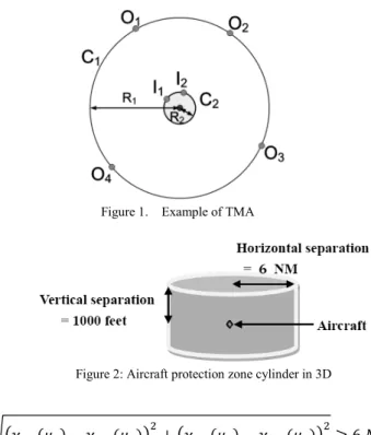
departure points, where the first ���� points are the arrival points and the remaining ���� ones are departure points. An example of TMA is shown in Fig. 1 with � = {�1,�2,�3,�4} and � = {�1,�2}.
The routes that we want to design connect some points on C1to some other points on C2. Let � ⊂ � × � be the subset which contains the pairs of points to be connected on C1 and
C2. Furthermore, we suppose that the proportion of flights on each route is given.
The design of SIDs and STARs can be done in an optimal way, with respect to a given criterion, such as minimizing the total distance flown by all flights. Therefore, the problem can be expressed as an optimization problem. In the following, we give the main elements of our optimization model.
Given (�, �) ∈ �, a route connecting points �� and �� can be defined as a function:
���: [0; 1] → ℝ3 (1) where ���(0) represents the starting point and ���(1) is the ending point. There are two possible cases: route ��� either starts from an entry point on C1and ends at an arrival point on
C2; or it starts from a departing point on C2and ends at an exit point on C1. This can be expressed by the following equations:
���(0) =��
���(1) =��� if 1 ≤ � ≤ ������ 1 ≤ � ≤ ���� (2) ���(0) =��
���(1) =��� if ����+ 1≤ � ≤ ����+���� and ���+ 1≤ � ≤ ���+����. (3) We denote the components of ��� in axis (�, �, �) by (����,����,����) respectively.
In this study, we consider two main constraints: the forbidden areas and the minimum separation. In TMA some special areas exist, where an aircraft is not allowed to fly, for instance geographical obstacles, big cities, military areas, etc. We refer to these areas as "forbidden areas". Furthermore, in air traffic control, aircraft have to be maintained at a minimum separation distance to reduce the risk of collision. The minimum vertical separation is 1000ft in TMA for all aircraft. Generally, the minimum horizontal separation in TMA is equal to 3NM. We consider this separation equal to 6NM, in order to take into account the deviation of aircraft from the pre-designed route. The aircraft protection zone is shown in Fig. 2.
The separation constraints are expressed as follows, ∀(�, �), (�, �) ∈ � , ∀(�1,�2)∈ [0; 1]
ICRAT 2014
Figure 1. Example of TMA
Figure 2: Aircraft protection zone cylinder in 3D
������(�1)− ����(�2)�2+�����(�1)− ����(�2)�2≥ 6 �� (4) �����(�1)− ����(�2)� ≥ 1000 ��. (5) We minimize the total distance flown by all the flights during a certain period.
� = ∑(�,�)∈����� ��� (6) where ��� is the length of route ��� and ��� is the proportion of flights on route ���.
III. SOLUTION APPROACHES
To deal with the difficulty of the problem, we propose a three-steps solution approach.
a. Compute an individual route by Fast Marching Method (FMM) and Gradient Descent method, where we take into consideration the forbidden areas.
b. Given a fixed order of the routes, compute sequentially the routes taking into account the minimum separation constraints.
c. Find an order minimizing (6) by applying Simulated Annealing (SA).
A. Designing one route
Given (�, �) ∈ �, we first compute a route yielding the minimal travel time from ���(0) to ���(1), see (2) and (3). The minimal-time optimal trajectory problem corresponds to a wave front propagation problem [3], [4]. In the isotropic case where the wave propagation speed does not depend on the direction, the equation that describes the evolution of the front is in the following form, known as the Eikonal equation:
Doctoral Symposium
‖∇�(�)‖�(�) = 1 (7) supplemented by the boundary condition
� ����(0)� = 0 (8) where � is the front position (corresponding to the aircraft position); �(�) represents the time at which the front reaches the point � and �(�) is the speed at the point �. In order to take into account the constraints, we associate a different propagation speed to points belonging to forbidden areas and to points located elsewhere, by expressing the speed at point � as follows:
�(�) = �1 − �(�)� ∙ � (9) with �(�) ∈ [0; 1) and � a constant value. In strictly forbidden area we consider �(�) = 0.99 and elsewhere �(�) = 0.
To solve the wave front propagation problem in the isotropic case, we apply the FMM developed by Sethian in [5]. The general idea of FMM is that the front propagates towards the points that it reaches at a minimum time. At the end of the evolution, we get the minimum time to reach any point in space starting from ���(0) . Then the Gradient Descent method is used to generate the route. It starts from the ending point ���(1) and moves towards the starting point ���(0) by taking steps proportional to the opposite of the gradient of �(�) at the current point �.
B. Generating all routes
Given an order of the routes, we compute sequentially routes as explained in the first step. In order to satisfy the minimum separation constraints, once a route is computed, this route and its protection zone are considered as additional forbidden area constraints for the remaining routes.
C. Getting an optimal order
By changing the order of routes, the length of each route is modified, because the routes computed previously have an influence on the shapes of the following routes. The number of possible choices for route order is �!, where � = ����(�), that can be rapidly increase with �. To get an optimal order, we apply a Simulated Annealing that is a stochastic global optimization method. It is conveniently applied to large scale problems.
Simulated Annealing works by emulating the physical process whereby a solid is slowly cooled so that when eventually its structure is “frozen”, a minimum energy configuration is obtained. For our application, the state space is the permutation group of the � routes and a solution is an element of this group, representing a selected order of routes. The algorithm starts with a random solution, then at each iteration a new solution is generated by selecting randomly two positions in the previous solution and inversing the order of the sub sequencing between them.
ICRAT 2014 IV. SIMULATION RESULTS
In this section we present the results obtained at each step
A, B, C in Section III.
We work with an airport with two parallel runways � and � . Their orientations are (12�, 30�) and (12�, 30�) respectively. The orientation 12� of runway � and the orientation 12� of runway � are only used for takeoff; the other two sides are only used for landing. The coordinate of the center � of the two circles �1 and �2 is (100 ��, 100��, 0 ��). Fig. 3 shows this configuration.
Moreover, �1= 100 �� and �2= 10 �� ; Entry/exit points are {�1,�2,�3,�4} and {�5,�6,�7,�8} respectively. Arrival/departure points are {�1,�2} and {�3,�4} respectively. The z-coordinates of points ��,� ∈ {1, … ,8} and ��,� ∈ {1, … ,4} are 25000�� and 4000�� respectively. Their x,y-coordinates are presented in Table.1. The number of flight is � = 20000; The pairs to be connected are � = {(�1,�1) , (�2,�1), (�3,�2), (�4,�2), (�3,�5), (�3,�8), (�4,�7), (�4,�6)} . The proportion of flight on each route is 5%, 20%, 15%, 10%, 5%, 15%, 25% and 5% respectively.
A. Designing one route
In this step, we firstly generate a route connecting the pair (�1,�1). Fig. 4 presents the simulation results. Three obstacles are taken into consideration. The area located in the center of an obstacle in dark gray is the surrounding area that can be flown over considering a penalty. The simulation result shows that the generated route is smooth and avoids the forbidden area.
B. Generating all routes
The simulation result is shown in Fig. 5 where the black routes are the STARs and the gray ones are the SIDs. The obstacles are unchanged.
Figure 3: Runway configuration
TABLE I. COORDINATES IN AXIS x AND y
�� �� �� �� �� �� �� �� x (km) 100 200 120 0 140 180 40 20 y (km) 200 100 2 100 194 40 20 160 �� �� �� �� x (km) 110 100 100 90 y (km) 100 90 110 100
Figure 4: Designing one route (the axes x, y, z have different scales; the
range of axes x and y is [0; 225km], the one of axis z is [0; 8.5km])
Figure 5: Generating all routes (the axes x, y, z are represented in the
same way as in Fig.4) C. Getting an optimal order
The simulation starts from a randomly generated order, with the initial total distance �����= 2204141 ��. By applying Simulated Annealing, we find the minimum total distance ����= 2008012 ��. The relative reduction ∆= (�����− ����)⁄���� is equal to 9.7%.
V. CONCLUSION AND PERSPECTIVES
In this paper, we introduce a methodology to generate automatically SIDs and STARs in TMA at a strategic level,
considering forbidden areas and minimum separation constraints.
In future work, in order to get closer to the operational context, we plan to consider some other constraints in TMA, for instance the route curvature, noise restrictions, runway capacities, etc. To deal with the more complex problem, the study will focus on mathematical modelization aspects as well as on the development of efficient determinist and stochastic optimization methods. Furthermore, we will address route design at tactical level taking into account weather events. Some routes can be blocked and have to be dynamically redesigned in order to address efficiently the demand.
ACKNOWLEDGMENT
This work has been partially supported by Civil Aviation University of China, by National Natural Science Foundation of China (NNSFC) through grant NNSFC 61201085 and by French National Research Agency (ANR) through grant ANR 12-JS02-009-01 “ATOMIC”.
REFERENCES
[1] D. M. Pfeil, "Optimization of airport terminal-area air traffic operations under uncertain weather conditions", M.S.Thesis, SSM, MIT, Cambridge, 2011.
[2] H. G. Visser and R. A. A. Wijnen, "Optimization of noise abatement arrival trajectories", Journal of Aircraft, 38 (2001), pp. 620–627. [3] B. Girardet, L. Lapasset, D. Delahaye, C. Rabut, and Y. Brenier,
"Generating optimal aircraft trajectories with respect to weather conditions", ISIATM, Toulouse, 2013.
[4] D. Bertsekas, "Dynamic programming and optimal control", vol 1, Athena Scientific Belmont, 1995.
[5] J.A. Sethian. "Fast Marching Methods". SIAM review, 41(2):199–235, 1999.
![Figure 4: Designing one route (the axes x, y, z have different scales; the range of axes x and y is [0; 225km], the one of axis z is [0; 8.5km])](https://thumb-eu.123doks.com/thumbv2/123doknet/14377515.505340/5.892.98.421.80.216/figure-designing-route-axes-different-scales-range-axes.webp)
