Publisher’s version / Version de l'éditeur:
Vous avez des questions? Nous pouvons vous aider. Pour communiquer directement avec un auteur, consultez la première page de la revue dans laquelle son article a été publié afin de trouver ses coordonnées. Si vous n’arrivez pas à les repérer, communiquez avec nous à PublicationsArchive-ArchivesPublications@nrc-cnrc.gc.ca.
Questions? Contact the NRC Publications Archive team at
PublicationsArchive-ArchivesPublications@nrc-cnrc.gc.ca. If you wish to email the authors directly, please see the first page of the publication for their contact information.
https://publications-cnrc.canada.ca/fra/droits
L’accès à ce site Web et l’utilisation de son contenu sont assujettis aux conditions présentées dans le site LISEZ CES CONDITIONS ATTENTIVEMENT AVANT D’UTILISER CE SITE WEB.
Building Research Note, 1985-11
READ THESE TERMS AND CONDITIONS CAREFULLY BEFORE USING THIS WEBSITE.
https://nrc-publications.canada.ca/eng/copyright
NRC Publications Archive Record / Notice des Archives des publications du CNRC :
https://nrc-publications.canada.ca/eng/view/object/?id=40241229-d876-45db-b123-dbc38b2ce700 https://publications-cnrc.canada.ca/fra/voir/objet/?id=40241229-d876-45db-b123-dbc38b2ce700
NRC Publications Archive
Archives des publications du CNRC
This publication could be one of several versions: author’s original, accepted manuscript or the publisher’s version. / La version de cette publication peut être l’une des suivantes : la version prépublication de l’auteur, la version acceptée du manuscrit ou la version de l’éditeur.
For the publisher’s version, please access the DOI link below./ Pour consulter la version de l’éditeur, utilisez le lien DOI ci-dessous.
https://doi.org/10.4224/40000477
Access and use of this website and the material on it are subject to the Terms and Conditions set forth at
Performance of an air-to-air heat exchanger and an exhaust air heat recovery heat pump
I :
I . 1 -
I .
National Research Conseil national
I
s1
Council Canads de recherche$ CanadaSer
TK1
3.92 ao. 235
c, 2
BWIG Division of Division des
Building Research recherches en bfitirnent
c
--- -
--
--
r Research E---
I,
s
Performance
of
an
Air-to-Air Heat
Exchanger and an Exhaust Air
Heat
Recovery
Heat Pump
by A. Kim
PERFORMANCE OF
A N
AIR-TO-AIR HEAT EXCHANGERAND AN EXHAUST AIR HEAT
RECOVERY
HEAT PUMPby A. Kim
Building Services Section Division of
Building
ResearchBRN
235ISSN 0701-5232
Ottawa, November 19135
TABLE OF CONTENTS
ABSTRACT/RESUME
. . .
:
. . .
I. . .
ISTRQDUCTIOK' 2
TEST 'HOUSES AND HEAT RECOVERY DEVICES
. . .
2. . .
Air-to-Air Heat Exchanger 2
Exhaust Air Heat Recovery Heat Pump
. . .
4. . .
TEST CONDITIONS AND MEASUREMENT
METHOD
5TEST RESULTS
. . .
5Air-teAir Heat Exchanger
. . .
5. . .
Exhaust Aii Heat Recovery Heat P u m p 10
. . .
PREDICTED ENERGY SAVINGS 12
. . .
Air-toc Air Heat Exchanger 13
. . .
Exhaust Air Heat Recovery Heat
P u m ~
14. . .
DISCUSSION 14
Comparison Between Heat Exchanger and Heat- Pump
. . .
14. . .
Cost Effectiveness of Keat Retovery Units 14
. . .
Defrost Performance 17SUMMARY
. . .
19. . .
ACKNOWLEDGEMENT , 19. . .
REFERENCES
,. . .
19. . .
ABSTRACT
The main objective of the study was to determine the thermal performance parameters of
an air-bair heat exchanger and an exhaust air heat recovery heat pump.
The experiment ally determined performance parameters were used to estimate the energy savings that would be achieved by using these devices in houses located in various regions
of Canada. Using the t s t house as a model, the predicted energy savings using the heat
exchanger were between 26U0 and 5000 kW-h and for the exhaust air heat recovery heat
pump, between 5000 and 7100 kWeh, depending on the degree-days of
the
location.Lg&tude avait pour but de d6terminer les parmgtres de rendement thermique d'un Cchangeur de chaleur air-air e t d'une pompe.
h
chaleur da rkup&ation de l'air extrait. Les p a r d t r e s d'essai ont semik
&valuer 1seconomies d'hnergile qui rkulteraient deI'utilkation de ees appareils dans des maisons de diverses localit& canadiennes. Pour
une maison pilote, les 6conomies prevua au moyen d'un kchmgeur de chaleur variaient entre 2600 et 5000 kW-h, et entre 5000 et 7100 kW-h
i~
l'aide d'me p o m pi
chaleurde
INTRODUCTION
Heat recovery devices are being sold in Canada even though their capability for retsverlng heat from the exhaust air is not well known. A project was carried out, therefore, to
determine the e&ct of an air-to-air heat exchanger and an exhaust air heat recovery heat pump on house energy use. The objectives of
this
study were to:(1) determine the thermal performance of the two heat recovery devices;
(2) estimate the house seasonal energy savings in w i o u s regions of Canada that would be achieved by such devices.
Since
the
primary function of these devices is ventilation, the heat recovery aspect is anoptional part of a mechanical ventilation system. The use of a heat recovery component can only be justified if the resultant energy savings are commensurate with the extra cost
of having such an option.
Fur
this reason, two types of residential heat recovery deviceswere tested to provide information needed for an economic assessment.
An air-teair heat exchanger consists of a heat exchanger core, a supply fan
and
an exhaust fan. The supply fan draws outdoor air into the house and the exhaustfan
discharges indoorair to the outside, through the heat exchanger core. As the two air streams pass through
the heat exchanger core,
heat
is transferred fromthe
exhaust air tothe
supply air-An exhaust air heat recovery heat pump replaces the
heat
exchanger by aheat
pump with the evaporator in the exhaust air stream and the condenser in the fresh air stream. In thisway, the heat extracted from the exhaust air by
the
evaporator, the heat dissipated by thecompressor,
and
the
fan energy, are transfer~ed to the fresh air.TEST
HOUSES ANDHEAT
RECOVERY DEVICESTwo
houses of the CHBA(HUDAC)/NRCMark XI
enesgy research project [l] were used for these experiments. House H4 was- used for theheat
exchangert a t
and houseB2
was used far the
EAHRHP
test. These two-storey houses withfull
basements are locatedsideby-side in a; developed residential area in
the
city of Gloucester,, Ontario; they are ofthe
same plan and construction and have similar air leakage characteristics.The
thermalresistance of the walls
is
3.5 m2-?C/W, of the basement it is 1.3,and
of
the
ceiling, 5.6.The
house volume is 386 m3.Each
house has a forced airheating
system with an electricfurnace. The fhrnace fan was on continuously during
the
experiment.Aii-to-Aim Heat Exchanger
One of the air-to-air heat exchanger models commonly used in
low
energy houses wasselected for testing. Figure 1 shows a sketch of the heat exchanger. The specifications of
I U I ( a 1 A I R - T O - A I R H E A l E X C H A N G E R HEATED AIR, TO INSIDE C O O E D AIR. TO OUTSIDE A I R AIR l b l E X H A U S i A I R H E A T R E C O V E R Y HEAT PUMP
TABLE
I
DESCRIPTIONOF THE
HEAT RECOVERIT DEVICES(a) Air-to-Air Heat Exchanger
Type doubIe cross-flow Size 121 x 38 x 56 cm
Core material potyolefin plastic Core surface area
12
m2Exhaust fan capacity 118
L/s
without any duct attachment Supply fan capacity 118L/s
without any duct attachmentDefrost control demand type defrost
Manufacture's stated 71% at 94 L / s and 83% at 47 L/s eEciency
(b) Exhaust Air Heat Recovery Heat P u m p Type air-to-air indoor unit
Size 47 x 69 x 62 crn
Exhaustfancapacity 52L/sat59.5Paofexternalstaticpressure Condenser fan capacity 260
L l s
at 59.5Pa
of external static prasure Compressor reciprocating R22 compressor, 7900 watt sizeDefrost contmI
timed
defrostCompressor control 1st stage of %stage thermostat
This
unit was equipped with a demand defrost contra1 for freeze-protection.The
supplyair (i-e., outside air) fan was turned off when
T,,,
5
S0C, whereT,,,
is the supply airtemperature downstream of
the
heat
exchanger care. The warm exhanst (i.e., indoor) airflowing through
the heat
exchanger core supplied the heat needed to melt the accumulatedfrost or ice.
The
supply air fan was turned on for normal heat exchanger operation, assoon as
T,,,
>
14°C.The installation of
the
air-to-airheat
exchanger isshown in
Figure 2.As
shown, the supplyair duct was not connected directly to the return plenum
of the
heating system.The
direct connectionwould
induce cold outdoor air flow through the heat exchanger corn during the defrost cycle and this would increase the defrost period.Exhaust
Air
Heat
'RecoveryHeat
PumpThe test
unit
was one of the two prototypes constructed specially forthe
Division of Building Research. Figure1
shows a sketch ofthe
unit.The
specifications of the unit aregiven in
Table
1.The
evap matar fan was set to operate continuously to providethe
ventilation air, but thecompressor, condenser fan and electric furnace were controlled by a tw-stage thermostat located
in the
living room.The
thermostat turned onthe
heat pump when the room temperature dropped below a set point {normally 2l0C), andthe
electric furnace wasA timer-control was used to defrost the evaporator coil. For every 34 minutes of operation,
the compressor was shut down far 4.5 minutes for defrosting. During
the
defrosting period,the exhaust fan continued to discharge the indoor air to the outside.
This
air flow suppliedthe
heat needed to melt the ice off the evaporator,Figure 2 shows the inskallation of the exhaust air heat recovery
heat
pump.TEST
CONDITlONSAND MEASUREMBNT METHOD
The experiments were conducted in unoccupied houses from December to April of the
1983-84 heating season, The nominal relative
humidity
ofthe
houses was 30-35% andthe indoor temperature was
21°C.
The
forced ventilation rate, i.e.,the
air flow rateof
the supplyand
exhaust fans, was set at 54Lls.
This ibw rate was chosen to emure ahause
air change rate of 0.5 ac/h, as recommended bythe ASHRAE
Standard 6281, Ventilation for Acceptable Indoor Air Quality (21.The
mechanical ventilafian systems andthe
furnace fanran continuously for the
whole
heating season. The heat recavery devices were activatedevery other week so that
the
effect of heat recovery units onthe
house heating demand could be determined.Data for the operation of the electric furnace, and for the mechanical ventilation systems with and without heat recovery devices in operation, as we11 as the weather data, were collected by a computer-based data acquisition system. The monitored variables were:
(a) indoor and outdoor air temperature,
(b) dry bulb and dew point temperature in the ventilation system (sensor locations are
shown in Fig. 2),
(c) energy use by the electric furnace, fans and compressor,
(d)
air flow rates of the supply and exhaust systems.Manual readings were taken daily for the air temperatures in the ventilation system, and
the energy uses of the electric furnace, fans and compressor, as a check on the computer
system. Also, the air change rates of the houses were measured at least twice each day
using the tracer gas decay method 131.
TEST RESULTS
Air-to-Air Heat Exchanger
The
thermal performance of a heat exchanger is usually described by:thermal effectiveness fact or ( E
)
,
%
,
temperature recovery factor
(TR)
,
%,
seasonal heat recovery factor (q),
%.
The
thermal effectiveness and temperature recovery factors are parameters used for rating an air-to-air heat exchanger and are given by reference 4:HOUSE AIR CIKCULATION SYSfEM SUPPLY
FQ
ELECTR l E FURNACE RETURF4-
BRANCH RETURN DUCr.Exwusr
l a l A I R - T O - A I R H E A T EXCHANGER
FLOW IU\K AND TEMPERATURE SENSORS
I)/
HOUSE A I R CIRCtlMTION. SYSTEM I1
1
C'\---
DAMPER -BYPASS HEAr EXCHANGER1
'\%
F,NSI
9I
TEMPERATURE SUJSDR F W !UTE AND EMPERATURE SENSOl b l EX HA US^ A I R HEAr RECOVERY H E A T P U M P
SUPPLY
ROOM A I R
Figure 2 Heat exchanger and EAHRHP installation.
and
where
ha,,
= enthalpy of air supplied to house by heat exchanger, J/g,ha,,
= enthalpy of outside air, J/g,hc,m = enthalpy of room air, J/g,
Ts,trr
= temperature of air supplied to house by heat exchanger, " C ,Tape = temperature of outside aik,
"C,
Te,w = temperature of room air, "C.
The
two equations give identical resultsif
the latent heat of vapourization associated withthe moisture in
the
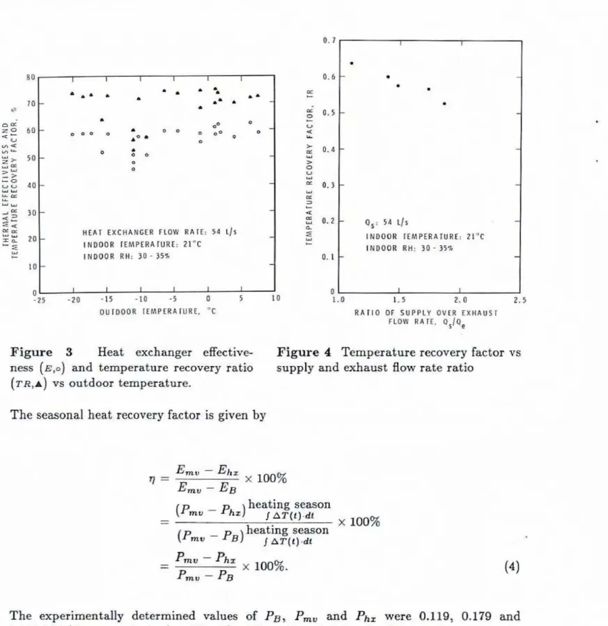
supply and exhaust air streams is neglected.Figure 3 shows
E
andT R
as a function of the outdoor air temperature, where E andTI2
calculations werebased
on measured values. As this figure indicates,E
and T R areindependent
of
outdoor temperature; the experimentally determined values are E = 58% andT R
= 72%. Figure 3 also shows five points which are substantially lower than theother values. These deviations occurred due t o the reduction in exhaust air Bow, which in turn was due. to frost buildup on
the
heat exchanger core. This effect is shown in Figure 4, where .the temperature recovery factor is plotted against the ratio of mass flow rates though the heat exchanger.The purchased heating energy for a house can be approximated by the following equation,
because basement heat loss and solar gain of a house are generally independent of outdoor temperature and approximately equal in value.
heating season beating season
Ei = - -
J
Gilt)dt
1 Pi
.
AT(t)
dtwhere
Ei
= purchased heating energy,kJ,
G;
= furnace power including the fan,k
W,
=
Pi
.
AT
(see Fig. 51, t = time, s,Pi
= house heat loss factor, kW/K,AT
= indoor-outdoorair
temperature difference,K,
i =
B,
mu, hs for no mechanical ventilation, mechanical ventilation only, andHEAT E X C H A N G E R FLOW RA'TE: 54 t / s I N D O O R IEMPERAIURE: 21°C INDOOR IIH: 3~ - 34%
-
- 2 5 -20 - 1 5 -10 -5 0 5 I 0 O U I D O O R TEMPERATURE. 'C 1 . 0 1,. 5 2 . 0 2 . 5 R A T I O O F SUPPLY OVER E X H A U S T FLOW K A 1 1 , Q = / Q ,Figure 3 Heat exchanger dective
Figure
4 Temperature recovery factor vsness ( E , O ) and temperature recovery ratio supply and exhaust flow rate ratio
( T R , A ) vs outdoor temperature.
The
seasonal heat recovery factor is given byheating season -
- (Pm - 'h.1 A T ( f ) . &
heating season x 100%
( p m v -
p-8)
J A*(i).dtThe experimentally deterwined values of
PB,
P,, andPh,
were 0.119, 0.179 and0.146
kW/K,
respectively (seeFig.
5).The
value of qfor
theheat
exchanger, there-fore, is 55%.
This
meansthat
the
heat exchanger was capable of recovering 55%of
theenergy increase due to the operation of the mechanical ventilation system.
Figure 6 shows the house air change rates with no mechanical ventilation,
with
mechanical ventilation 'done, and with mechanical ventilation and heat exchanger. The house air change rates with mechanical ventilation, and with and without the heat recovery, were8 I I I I I I L I ,'I /
n NO MECHANICAL VEMIl LAIIOM. 1 P, = 0.119 ~ W / K
7
-
0 MECHANICAL VVENTlLAilON W l I H HEAT
EXCHANGER. Phx = 0.146 kW/K 4 - - 3 - - - + 0 5 10 15 20 25 30 3 5 4 0 65 50 D A I L Y A V E R A G E T E M P E R A T U R E D I F F E R E N C E . A I . K
Figure 5 Daily average furnace power demand of the heat exchanger test house (H4).
-
MECHANICAL VENFlLAllON ONLY0 MECHANICAL VENTICATION W l l H HEAi MCHANGER
NO MECHANICAL VENTliAllON
l E M P Z R A T U R E D l F F E R E N C E . K
almost identical for an indoor-outdoor temperature difference less
than
25M.
For highertemperatwe different-es, the house air change rate without heat recovery w= greater than that with heat recovery. This was caused by a reduction in the exhaust air Aow rate due
to ice or frost buildup in the heat exchanger core.
For a temperature difference greater than 20
K,
typical Canadian winter conditions, thehouse air change rate was about 0.69 ac/h with mechanical ventilation and about 0.23 ac/h
without mechanical ventilation.
Exhaust Aii Heat Recovery Heat
Pump
The hherrnal perfomance of the exhaust air heat recovery heat pump is described by the
coefficient of performance (COP), which is given by
I=-
0
'
-
dt
COP =
,,
.where
Q , = heat rejection rate of the condenser,
W,
= mc p Cp(Tc - T i ) ,
W
= power demand of the heat pump, W,T
'
= time period, s,m, = air flow rate through the condenser, L/s,
p = density of air flowing through the condenser coil, kg/m3,
C, = specific heat of air,
J/
(g.Kj
,
T,
= air temperature downstream of the condenser coil,OC,
T;
= air temperature at the condenser fan intake, " C .Equation
5 was used to caIculatethe
COP fromthe
experimental data for time periodswhen
the
outdoor air temperature wasbelow
the
bdance point temperature ofthe
house- heat pump system (i.e., when the heat demand by
the
house to maintain room set pointtemperature was greater than the output
of
the heat-
pump).The
average COP forthis
condition was 2.0; this value was based on
the
following measured average values,for the heat pump operation cycle of 34 minutes, during which the compressor and supply
0 NO MECHANICAL VENIIUIIIIIN
IG = PB-nrr
B
0 b1ECHANICAL VENT1 U l l O N W 1 IH EAHRHP
15
1
lGHp = PHp 'AT - GX# m' a a MCHANICAL VENlllA ' G ~ ~ = P * EAHRHP INPUT P M E RP
a MCHANICAL VENlllAllON ONLY 'GMV = PMV ' A11 I; - * EAHRHP INPUT P M E R 4 - 3 - 5 10 15 20 25 3 0 35 40 45 5 0 D A 1 LY A V E R A G E lEMPERATUUE ? I FFERENCE. A t , K
Figure 7 Daily average furnace power demand of the
E
AHRRP te,st house(HZ).
The
daily
average furnace power for house #2 is shown in Figure 7 for the three testconditions: with no mechanical ventilation (house as
is,
i.e., 0.2aclh),
with the exhaustr only ventilation system operating albne (0-5 ac/h),
and with the exhaust air heat recoveryheat pump in operation (0.5 ac/h).
The daily average furnace power increased linearly with
the
indoor-outdoor temperature difference. At a temperature diierence of about 19K,
the daily average furnace powerwith
the
h a t pump in operatian is nearly zero (Fig. 7). This indicates that for an outdoortemperature of 2°C or higher (i-e.,
balance
point temperature),the
heat recovered fromthe
exhaust air alonewm
sufficient to meetthe
house heatingdemand.
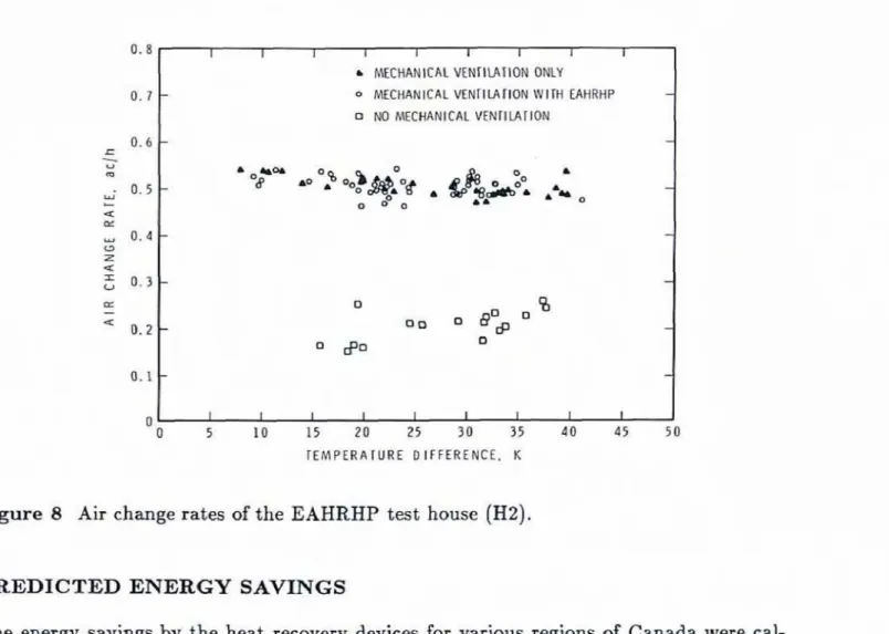
Measurements indicate that the house air change rate without any mechanical ventilation
is
0.2 a ~ / h (see Fig. 8). Because of
this low
natural ventilation,the
exhaust-only mechanical ventilation system determinesthe
house air change rate.Thus
whenthe
exhaust-onlymechanical ventilation system (heat pump) is
installed
and the exhaust flow rate is setat 0.5 ac/h,
the
total houseair
change rate also becomes 0.5 ac/h. (The operation ofthe
compressor andthe
air circulating fan of the heat pump does not &ect the house airTEMPERA l U R E D I F F E R E N C E , K
0 . 8 I I I 1 I I 1 I I
Figure 8
Air
change rates of theEAKRHP
test house (H2).0.7
PREDICTED ENERGY
SAVINGSKCHAM ICAL VEHrItAilOM ONLY
- 0 MECHANICAL MNIIlAIION W IIH EAHRHP -
NO MECHANICAL VENlllATlON
The energy savings
by
the heat recovery devices for various regions of Canada were cal-culated by a computer program
(EASI3),
developed at the Division of Building Raearch,and using experimentally determined performance factors of the heat recovery devices.
The EASI3 program gives the monthly house heating requirement based on the hourly
calculation of house
heat
lass rate and internal m d solar gains.The
following datawhich
describethe.
test house are required as input to the EASI3program-
(i) dimensions of
the
house (see Ref. 1),
(ii) area and
R
value ofall
building components (seeRef.l),
[iii)
~hading
coefficient and orientation of each window (north = 0.53, south = 051 and east = 0.47),(iv) seasonaI average house air change rate (described in previous chapter),
(v) interna1 heat gain (1.0
k
W)
,
and(vi) number of occupants (zero).
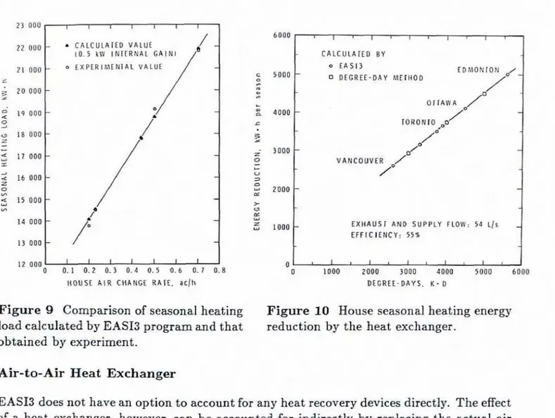
As a check on EASI3 program calculations, Figure 9 compares the energy use predicted by EASI3 and that calculated from Eq. 3 using
the
measured heat loss factor for the twoC A L C U L h l E D VALUE t O . 5 kW INTERHAL GAIN1
4 EXPERlMEHfGL VALUE
12 000
0 0 . 1 0.2 0.3 0.4 0 . 5 0.6 6.7 0.8
HOUSE AIR CHANGE R A I E . acjh
v l , , , , , i , l , C A L C U L A I E D B Y 0 € 4 5 1 3 EDMOMION - DEGPTE-DAY METHOD O r r A W A - I O R O N f O
/
/1
--
V A N COUVEEE X H A U ~ 1 AHD SUPPLY FLOW: 54 L ~ S
EFFICIENCY: 55%
1
DEGREE-DAYS. K - 0
Figure 9 Comparison of seasonal heating Figure 10 House seasonal heating en-0
load calculated by EASB program and that reduction by the heat exchanger.
obtained by experiment.
Air-to-Air Heat
Exchanger
EASI3 does not have an option to mount for any heat recovery devices directly. The effect
of a heat exchanger, however, can
be
accountedfor
i n d i r ~ t l y by replacing the actual air change rate with the apparent air change rate. The apparent air change rake that accountsfor
the
operation of the heat exchanger in the test house was calculated to be 0.44 ac/h(calculation procedure is given in Appendix A).
The
calculated house heating energy reduction- as a result of the use of the heat exchangeris shown in Figure 10 for various places in Canada. It indicates that the heating energy
reduction per season increased linearly from 2500 kW-h to 5000
k
W.h as the heating degree-day [based on 18°C) increased from 2800 to 5600K-D.
For comparison, Figure 10
also
showsthe
energy savins determinedby
EASI3(in.
kW-hper season) and by the fo1Iowing equation
E,
= energy saved by heat exchanger, kJ/season,'I,, = air change rate with mechanical ventilation, ac
f
h,Ihz = apparent air change rate, a,c/h,
V = house volume, m3,
D
= heating degree days, [based on 2I0C), K-D.As
expected, energy savings pxedicted by Eq- 6 and by EASI3 are equal.Exhaust Air Heat Recovery Heat Pump
EASI3 was modified to include
the
option to estimatethe
energy savingsby
a heat pump. It was assumed that the output ofthe
heat pump was 3.22kW
andthe
COP was 2 (i-e.,measured perhmance parameters of
the
testEAHRRP). AIso,
a constant air change rate of 0.5 ac/h was used in these calculations.Figure 11 shows the energy savings per heating season by the heat pump for variouls regions
of Canada. The energy savings increased from 5000
k
W.h
to7100 kW-h
asthe
heating degree days increased from 2600 to 5800K-D.
The heat recovered per heating season from the exhaust air by the heat pump was sufficient to meet 70% ofthe
house heating energy requirement wen at Edmonton, where the winter climateis
severe. In addition, calculations were carried out for a range ofCOP
values to determine the effect of the COPrsn energy savings. The results of these calculations are shown in Figure 12.
DISCUSSION
Comparison Between Heat
Exchaxlger
and
Heat
PumpFigure 13 cumpares
the
calculated energy savings obtained by the two heat recovery d+vices.
To
make such a comparison, it was assumed thatthe
house under considerationwas tightly built and therefore
the
natural air infiltration throughthe
house envelope wasnegligible. Based on a constant house air change rate of 0.5 aclh supplied completely by
the mechanical ventilation system, the energy savings obtained by the
heat
pump would be 1.4to
2 times those obtained bythe
heat exchanger.Cast Effectiveness
of
Heat- Recovery UnitsThere
is a wide variety ofmethods
bywhich
the benefits of an energy conserving optioncan be weighed against its cost.
Each
has its advantagesand
disadvantage-In
this study,the "Present Worth" method seems t o be most applicable because
the,
installed cost ofthe
EARRHP is not known yet.
The present worth is an amount of money
which,
if borrowed and repaid annually atthe
8 000 1 I I I 1 I '\ OUlPUl W E R : 3-22 h COP; Z 7500
-
\ . C EXHAUS I FLW RAIE: 54 us a 0 Z C 0 ~ E R G Y S A V I ~ ~ G S B Y M H U I P U M P x OF WAIINC LMD suPnlm BY ME HWT PUMP IL 0 40 DEGREE-DAYS. K - DFigure
I1
House seasonal heating energy reductionby
theEAHRHP.
1 0 0 0 0 - c 9 0 0 0 - 0 n 9 0 .* F. X s a o o - t 2 V A N C O U V E R
-
7 000-
C) C v 3 6000 - nc 2- c9 az W saoo - 4000 - O U T P U T POWER: 3.22 k W - E X H A U S T FLOW RATE: 56 L ~ S 3 000 I I I I I 1. 0 1.5 2 . 0 2.5 3 . 0 3 . 5 4 . 0 C O PFigure 12 Effect of
COP
on energy savings by EAHRHP. 15I t 1 I I I
0 ENERGY SAVINGS BY EAHRHP
I
Figure 13 Comparison of house heating energy reduction attained wing
the
heat ex-changer and
the EAHREIP-
7000 5 0 q 6008 m Y) L w d C: 5 0 0 0 3 ; 4000 a - + U 3 0 3000 W
=
r u ZOO0 Z u 1000 0would just be repaid by the time the device had t o be replaced. It is calculated using the following equation [5] :
a ENERGY SAVING5 BY HEAi EXCHANGER
-
- --
- SUMMRlAND - A/'
EhHRHP:VANCOUVER OUlPUT WER: 3.22 kW
- COP: 2 -
EXHAUST FLW RATE: % US INFILTRATION: 54 US
- HEA r MCHANGER: -
E X M U ST AND SUPPLY FLW RA YF: Sd d3
EFFICIENCY; 55% I I i I I I 2500 3000 3500 4000 4 5 D O 5000 5500 6000 where
a
~ E ~ - R A K L .L-
.n
B - C a=- l + ePW
= the present worth of the annual energy savings over n years,C
= the first year saving,a = the effective interest rate,
e =
the
rate atwhich
energy costs are expected to incrwe,d = the interest rate on money borrowed to purchase the energy-saving option,
The service life
of
the heat recovery unit is difficult to estimate. For this study, both5 years and 10 years have been considered. Ten years WEIS selected because many building
owners are unwilling t o look beyond 10 years and, therefore,
this
represents their maximumallowable n value.
In the present study, electricity has been chosen as the source of house heating energy for
simplicity in calculation. Utility rates are different for different p ~ a s of Canada and vary from
3#/kW*h in
Winnipeg to 6,3{/kW-hin
Halifax,
according to an energy costs survey done in late 1983#.
However, for most cities, the utility cost is about 4#/kW-h and thisvalue was used in this study,
The annual
interest rate ( i ) was assumed to be 13% over the period under considerationbased
onthe
prime tending rate of 1984. The average annual rateof
expected utility costincrease (e) for various locations in Canada was estimated at 8%, based on the recent
study by Energy, Mines and Resources Canada,
which
developed estimates of escalationrates for gas, oil and electricity for a major city
in
each province for the period from 1983to 1997 [7].
The
calculated present worth values of the energy savings by the heat recovery units over5-year and l@year periods are shown
in
Figure 14 for various b c a t i ~ n ~ in Canada. If either of these types of heat recovery device can be purchased and installed at a cast thatdoes not exceed the present worth of the savings that it
will
produce, itis
"cost effective". The best aption is the one that has the largest difference between present worth and thecost of
the
unit.The result
in
Figure 14 was obtainedfor
a housewhich
is same size asthe
CHBAINRC MarkXI
test house andhas
a negligible natural air infiltration rate.If
theheat
recoveryunits are installed in a house which is leakier and/or smaller than the test house, the
air flow rates
(both
exhaust and supply flow rate) ofthe
heat recovery units shouldbe
reduced and, therefore, the energy savings
by
the units would also be reduced. This resultsin reduted present worth of the energy savings. Defrost Performance
When the
indoor
(exhaust) air Aows throughthe
heat recovery units, the exhaust airtemperature drops as
the
heatfmm
the exhaust air is removed. Dependi* on the-operatingconditions,
the
exhaustair
temperature may drop below the dew paint temperature of theair, and if the dew point temperature is
bdow
the freeeing point, then ice or frost starts toform in the exhaust side of the heat recovery unit. Occasional defrost, therefore,
is
needed
to
melt the ice o f f theheat
recovery core to maintainthe
design values of air %ow andheat
recovery core thermal resistance.
The heat exchanger was defrosted by stopping the flow of outside
air
through the unitand
using the heat from the exhanst air to melt ice off the heat exchanger core. Defrost operation was controlledby
the temperature of the supply air downstream of the heat exchanger core as described before. Experimental observations indicated that this type ofa HEAT EXCHANGER
n = SERVICE LIFE OF UNIT
i -13%; e-8%; UTILITY C O S T a 4 t I I ; W - h
1
2500 3000 3500 4000 45'00 5000 5500 6000 D E G R E E - D A Y S . K - D
Figure 14 Present worth of the annual energy savings obtained by
the
heat exchangerand
the
E
AHRXIP
for various locations in Canada.defrost control creates problems because
the
supply air temperature downstream ofthe
heat exchanger core is not a good indicator of the conditions of frost accumulation. During the test of the heat exchanger, there was a heavy accumulation of ice on the outside surface of the uninsulated supply and d u s t duct when the outdoor weather was very
cold (below -15°C).
This
ice melted and wettedthe
flour asthe
outdoor temperature rose.Therefore, both
the
supply and exhaust duct of the heat exchanger should be insulated. The heat pump was defrostedby
shutting downthe
compressor for 4.5 minutes after every29.5 minutes. The defrost operation was controlled by a timer regardless of the condition of the evaporator. Under cold weather conditions, the exhaust air flow rate through the
evaporator started to decrease 20 minutes after the end of the last defrost cycle, The air
exhaust rate decreased gradually;
the
maximum reduction sometimes was as much as 15%of the original value.
The
d a u s t air flow ratewould
normally be back to its original value 4 minutes afterthe
defrost operation was initiated.The
exhaust air temperature leaving the evaporator was -3OC,which
was 7K
higher than the design value.The above were the only major problerns encountered in
the
operation of these two heatSUMMARY
( I )
The
measured average seasonal heat recovery factor of the heat exchanger was 55%,while the value stated by the manufacturer is 70 to 80% at steady state conditions.
(2) The measured output of the heat pump was 3.22
kW
and theCOP
was 2.0.The
heat pump could meet all the heating demand of the test house for
an
indaor-outdoor temperature difference of up to 19K.
(33 The predicted energy savings by the heat exchanger for the test house with an air
change rate of 0.69 ac/h increased from 2600 to 5000 kWeh as the degree days (based
on 18'C) increased from 2600 to 5600
K-D
for various locations in Canada.(43 The predicted energy savings by the exhaust a h heat recovery heat pump for the test
house with an air change rate of 0.5 ac/h increased fmm 5000 to 7100
k
W-has
the heating degree days increased from 2600 to 5600K-B
for various locations in Canada.( 5 ) For tbe same house with the same air flew rate through the ventilation system, the.
predicted energy savings by the heat pump were 1.4 to 2 tima greater than those by
the heat exchanger.
The
author wishes to acknowledge the contribution of Dr. C.Y.Shaw
inthe
preparationof this paper.
REFERENCES
I. Quirosette,
R.L.,
The Mark
XI Energy Research Project-
Design and Construction.National Research Council Canada, Division of Building Research, Building Research Note 131, Ottawa, Oct. 1978, 20 p.
2. ASHRAE Standard 62-81, Ventilation for Acceptable Indoor Air Qua6ty. ASHRAE, Atlanta, 1981.
3. Shaw,
C.Y.,
The Effect of Mechanical Ventilation on theAir
Leakage Characteristicof a Two-Starey Detached House. National Reearch Council Canada, Division of Building Research, Building Research
Mote
204, Ottawa, July 1983, 26 p.4. Fisk, W.J., Archer,
K.M.,
Chant,R.E.,
Hekmat,I?.,
Offerman,F.3. and
Pedersen,B.S., Freezing
in
Residential Air to Air Heat Exchangers:An
Experimental Study. Lawrence Berkeley Laboratory, University of California, Contract report LBL-16783, UC-38, prepared far U.S.
Dept. of Energy, September 1983.5. Stephenson, D.G., Determining the Optimum Thermal Resistance for Walls and Roofs. National Research Council Canada, Division of Building Research, Build-
ing
Research
Note 105, Ottawa, January 1976, 13 p.6. Spider Engineering Associates, Analysis of Residential Space Heating Systems - Final Report. DSS contract No. OSRBZW026 for Division of Building Research, National Research Council Canada.
7. Lee,
P.C.,
An Economic Studyd
Residential Space Heating and Cooling in Canada.APPENDIX A APPARENT AIR CHANGE RATE
B y
definition, the value of the apparent air change rat-c. ( I a ) is such that the calculatedpurchased heating energy for a house without heat exchanger and with air change rate
I, equals the purchased heating energy for the same house with heat exchanger and with
actual air change rate I,, (i.e., E, = Eh,).
Equation 4 relates Ehz, Emv,
EB
and q and, therefore, it can be used to calculate I, asfollows:
Solution of Eq. 4 for Eh, gives
House heat transmission loss ( E ~ ) is independent of air change rate. Purchased energy for heating ventilation air is
where
I',
= air change rate andK
is a constant; substitution of the above in Eq.lA givesSample calculation:
Calculate