HAL Id: hal-01100914
https://hal-univ-rennes1.archives-ouvertes.fr/hal-01100914
Submitted on 7 Jan 2015
HAL is a multi-disciplinary open access
archive for the deposit and dissemination of
sci-entific research documents, whether they are
pub-lished or not. The documents may come from
teaching and research institutions in France or
abroad, or from public or private research centers.
L’archive ouverte pluridisciplinaire HAL, est
destinée au dépôt et à la diffusion de documents
scientifiques de niveau recherche, publiés ou non,
émanant des établissements d’enseignement et de
recherche français ou étrangers, des laboratoires
publics ou privés.
On-off closed-loop control of vagus nerve stimulation for
the adaptation of heart rate
Hector Romero Ugalde, Virginie Le Rolle, Alain Bel, Jean-Luc Bonnet, David
Andreu, Philippe Mabo, Guy Carrault, Alfredo Hernández
To cite this version:
Hector Romero Ugalde, Virginie Le Rolle, Alain Bel, Jean-Luc Bonnet, David Andreu, et al..
On-off closed-loop control of vagus nerve stimulation for the adaptation of heart rate. EMBC:
En-gineering in Medicine and Biology Conference, Aug 2014, Chicago, United States. pp.6262-6265,
�10.1109/EMBC.2014.6945060�. �hal-01100914�
On-off closed-loop control of vagus nerve stimulation
for the adaptation of heart rate
Hector Romero Ugalde
1, Virginie Le Rolle
1, Alain Bel
2, Jean-Luc Bonnet
3, David Andreu
4,
Philippe Mabo
1, Guy Carrault
1and Alfredo I. Hern´andez
1Abstract
Vagus nerve stimulation (VNS) is a potential therapeutic approach in a number of clinical applications. Although VNS is commonly delivered in an open-loop approach, it is now recognized that closed-loop approaches may be necessary to optimize the therapy and minimize side effects of neuro-stimulation devices. In this paper, we describe a prototype system for real-time control of the instantaneous heart rate, working synchronously with the heart period. As a first step, an on-off control method has been integrated. The system is evaluated on one sheep with induced heart failure, showing the interest of the proposed approach.
I. INTRODUCTION
Vagus nerve stimulation (VNS) has been identified as a potential therapeutic approach in a number of clinical applications, such as epilepsy, supra-ventricular arrhytmias and heart failure (HF) [1]–[7]. Although VNS is commonly delivered in an open-loop approach, it is now recognized that adaptive, closed-loop approaches may be necessary to optimize the therapy and minimize side effects of neuro-stimulation devices [8]–[11]. A variety of physiological data may be employed as control variables in a closed-loop approach, depending on the target function of VNS control. Previous works in the literature have been mainly focused on the control of heart rate, since this variable is particularly important and is readily observable.
To our knowledge, the first attempt to provide a closed-loop VNS approach was proposed by Bilgutay et al. [4]. In their paper, three models of “vagal tuners” are proposed. Two of them are implantable, but manually activated. The third one is an external device, which is automatically activated when the RR interval falls bellow a threshold value. In such vagal tuners, VNS is delivered synchronously with the R-wave, detected from the ECG signal. Although the two manual approaches have been developed and evaluated on 10 dogs, no details are given on the development or evaluation of the automatic approach. Other closed-loop systems for VNS control, based on the adaptation of the VNS frequency are proposed in [12] and [11]. In [12], a control system, based on the classical cumulative sum control chart technique, adjusts stimulation frequency in order to regulate the average ventricular rate during atrial fibrillation in dogs. VNS is delivered continuously to the left vagus nerve, without any cardiac beat synchronization. Initially, the stimulation is delivered at a nominal frequency of 1 pulse/s and then the controller automatically updates the left vagal stimulation frequency. The other stimulation parameters have been manually defined and fixed during the whole test for each dog (pulse width = 1 ms and current = 2 – 5 mA).
Tosato et al. [11] use a proportional-integral (PI) controller, which also adjusts the stimulation frequency, in order to regulate heart rate in pigs. In their work, different tests are presented, including the stimulation of the left, right and both vagus nerves. For each test, a different stimulation amplitude is kept constant in the range 4 – 15 mA, the pulse width is fixed to 0.3 ms and the controller automatically updates the “optimal” stimulation frequency within the range 0 – 20 Hz in three pigs and 0 – 25 Hz in four pigs. The update rate of the controller is kept constant within a test, but varies for each test within 10 to 60 updates/s and the stimulation is delivered asynchronously.
In this paper, we describe a prototype system for real-time control of the instantaneous heart rate of a sheep with induced heart failure, through adaptive vagus nerve stimulation. The ovine animal model has been chosen, since it is particularly robust to the induction of heart failure through myocardial infarction. As opposed to the above-mentioned methods, the proposed approach works synchronously with the heart period, which implies additional constraints. As a first step, we have integrated an on-off control method, in which the burst of VNS pulses are conditionally delivered to the right vagus nerve, 50 ms after an R-wave is detected from the ECG.
The paper is organized as follows: First we describe the sheep preparation and the on-off closed-loop control system used in this work. In Section III, the paper discuses the results obtained in the different tests applied to our control system. Finally conclusions are given in Section V.
1H. Romero, V. Le Rolle, P. Mabo, G. Carrault and A.I. Hern´andez are with INSERM U1099 Rennes F35000, France, and also with Universit´e de
Rennes 1, LTSI, Rennes, F35000, France (email: alfredo.hernandez@univ-rennes1.fr).
2A. Bel is with Assistance Publique - Hˆopitaux de Paris, Hospital European Georges Pompidou, Paris, France and also with INSERM U633, Laboratory
of Biosurgical Research, Paris, France.
3JL. Bonnet is with Sorin Group, Clamart, France.
II. METHODS A. Sheep preparation
The present study was conducted under the approval issued by the French ethics committee for animal experimentation. Heart failure was induced in one sheep (body weight 35 kg) by occluding 3 marginal and 1 diagonal coronary arteries. During the same intervention, a bipolar pacemaker lead containing an intracardiac accelerometer was placed in the right ventricle (SonRTipT M lead, Sorin CRM, Clamart, France) and a cuff-type VNS electrode (Cuff electrode C4D3-1, Obelia)
was implanted on the right vagus nerve, at a cervical site. Three months after inclusion, the ejection fraction of this sheep was measured at 38 %, confirming HF induction. A new experimentation was then performed in order to test the VNS control system.
During this second intervention, the sheep was initially anesthetized with Propofol and a morphine bolus. After this initial phase, the sheep was anesthetized by Etomidate (100 µg/kg/min). The surface ECG, the intracadiac ElectroGraMs (EGM), the left intra-ventricular pressure and the body temperature (37oC) were monitored during the whole procedure. Breathing
was artificially controlled at 0.3 Hz (18 breath/ min). After a verification stage of the implanted instrumentation (in particular VNS electrode impedance and EGM quality), the evaluation experiment of the proposed control system, described in Section II-C, was implemented.
B. On-off closed-loop control system
The closed-loop control system (see Fig. 1) comprises: 1) a bipolar sensor (SonRTipT M lead, Sorin CRM, Clamart, France), placed in the right ventricle, in order to acquire the EGM, 2) a cuff-type VNS electrode (Cuff electrode C4D3-1, Obelia), implanted on the right vagus nerve, at a cervical site and used for vagus nerve stimulation, 3) the prototype (Proto INTENSE V 1.2) which contains a neurostimulator device and an analog signal conditioning unit (EGM), 4) a data acquisition (DAQ) device NI USB-6211, and 5) an application developed on LabView, which receives and process the EGM signal in real time and implements the VNS control loop method.
Fig. 1. Closed-loop control system.
In the current development version of the stimulator, we do not have programmatic, real-time access to all stimulation parameters. Only a “trig in” feature is available (see Fig. 1), which allows us to precisely activate a pre-programmed VNS profile. With this constraints in mind, the following control application, based on a classical on-off approach, was developed in LabView.
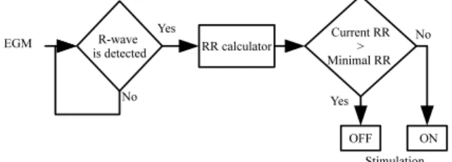
Fig. 2. LabView application: R-wave detection, RR calculator and on-off algorithm.
Fig. 2 shows the algorithm on which our application is based. Real-time R-wave detection is applied to the measured EGM signals, to estimate the instantaneous RR interval (and the instantaneous heart rate, HR). If the current RR interval is lower than the minimal target RR value, then the stimulator is set to on, i.e. the pre-programmed stimulation profile is delivered. If the current RR interval is greater than the minimal target RR, the stimulator is set to off, i.e. no stimulation is delivered.
The EGM signal is acquired using a NI USB-6211 data acquisition (DAQ) device. The analog signal activating the “Trig in” input of the neurostimulator is sent by using an analog output of the same DAQ device.
C. Experimental application of the control system Experiments were performed in three steps:
1) Before starting the control system, different VNS configurations are applied, in order to evaluate, for each one, its impact on the instantaneous RR, for a given sheep.
2) A VNS configuration showing a sufficient variation on HR (RR during stimulation − RR before stimulation > 200 ms) is selected and programmed into the stimulator.
3) The control system is activated, with different target HR values.
For this sheep, the pre-programmed VNS configuration was the following: frequency = 31 Hz, delay from R-wave = 50 ms, pulse width = 0.24 ms, and current amplitude = 2 or 3 mA.
III. RESULTS AND DISCUSSION
In order to validate the proposed on-off control system, four tests are presented in this section. For all these tests the VNS frequency is fixed to 31 Hz and the pulses are delivered conditionally, 50 ms after an R-wave is detected.
A. Test 1: Minimal target RR = 500 ms, VNS current = 3 mA, Number of pulses = 2.
In the first test, the objective is to reach a minimal RR of 500 ms. The stimulation current is set to 3 mA and two pulses are delivered. Results are presented in Fig. 3, which presents the detected instantaneous RR intervals with respect to beat number, before, during and after the application of the closed-loop VNS.
20 40 60 80 100 120 140 160 300 350 400 450 500 550 600 650 700 750 beats (number) RR(ms) Desired RR Current RR Closed−loop VNS
Fig. 3. RR interval when the minimal target RR = 500 ms with the stimulations parameters 3 mA and 2 pulses.
Fig. 3 shows that the spontaneous RR interval of the sheep (around 480 ms) is significantly modified during the activation of the control system. The minimal target RR is reached with the selected stimulation parameters. However, the RR oscillations around the minimal target RR value are quite high. These oscillations are inherent to the on-off algorithm. In fact, when a stimulation is delivered with the pre-programmed parameters, the RR interval reaches values around 600 ms. When the stimulator is turned off, the RR interval tends to fall to the spontaneous RR interval (around 480 ms). According to the on-off algorithm presented above, when an R-wave is detected and the RR interval is lower than the minimal target RR, i.e. 500 ms in this example, then a stimulation is delivered and the minimal target RR is reached. Therefore, in the next R-wave the RR interval is greater than the minimal target RR and the stimulator is set off. For this reason, in this example, the stimulator switches on and off each time an R-wave is detected. We can observe in Fig. 3, beats from 118 to 122, that the VNS does not have the same effect as for the rest of the beats. This is due to normal physiological variations. In this sense, in the following test, we set the minimal target RR near to the maximal instantaneous RR values that the stimulator can reach with the pre-programmed stimulation parameters, we test how the on-off algorithm reacts to these oscillations.
B. Test 2: Minimal target RR = 600 ms, VNS current = 3 mA, Number of pulses = 2.
In the second test (see Fig. 4), the minimal target RR is set to RR = 600 ms and the stimulation parameters are set as in the first test, i.e., the stimulation current is set to 3 mA and two pulses are delivered.
20 40 60 80 100 120 140 160 180 350 400 450 500 550 600 650 beats (number) RR(ms) Current RR Desired RR Closed−loop VNS
Fig. 4. Minimal target RR=600 ms, 3 mA and 2 pulses.
20 40 60 80 100 120 140 400 450 500 550 600 beats (number) RR(ms) Current RR Desired RR Closed−loop VNS
Fig. 5. Minimal target RR=600 ms, 2 mA and 2 pulses.
C. Test 3: Minimal target RR = 600 ms, VNS current = 2 mA, Number of pulses = 2.
In the third test a different set of parameters is pre-programmed, and the same objective is appointed, i.e., minimal target RR = 600 ms and two pulses are delivered. However, the stimulation current is reduced to 2 mA. The results of this test are displayed in Fig. 5.
With the stimulation parameters used in this test (Fig. 5) the minimal target RR can not be reached. Therefore, the stimulator is set on during the entire closed-loop VNS phase.
All the previous results show the importance of modifying the most sensitive VNS parameters within the control loop, in order to 1) minimize RR oscillations around a target RR interval and 2) cope with physiological variations of the RR response to the pre-programmed VNS profile. The following section presents results in which one of the most sensitive VNS parameters (number of VNS pulses) is modified manually during a test with dynamic target RR definitions.
D. Test 4: Manual dynamic modification of the number of VNS pulses
In order to improve our control system in a future work, we decide to test the effect of the number of VNS pulses in the instantaneous RR interval. As already mentioned, in the current version of the stimulator (Prototype INTENSE V 1.2), only a “trig-in” feature is available. With this constraint in mind, a new application was implemented in LabView. This application works as follows: 1) one pulse (pulse width = 0. 24 ms, current = 2 mA) is pre-programmed on the stimulator prototype, 2) the LabView application triggers the pre-programmed pulse N times at a frequency of 31 Hz, generating a VNS sequence of N pulses, pulse width = 0. 24 ms, current = 2 mA and frequency = 31Hz. Even if our perspective is, in a future work, to automatically adapt the VNS parameters, in this test, the number of pulses is manually changed.
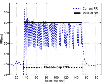
Fig. 6 shows the instantaneous RR response to varying minimal target RR and number of pulses. Beats from 35 to 100 (Fig. 6 b)) correspond to a minimal target RR = 500 ms and three pulses. After 100 beats, the minimal target RR is changed to 550 ms (Fig. 6 c)). At 145 beats, the minimal target RR is changed to 600 ms (Fig. 6 d)). Beats from 245 to 319 correspond to an unreached minimal target RR of 650 ms (Fig. 6 e)). Intended to reach the minimal target RR = 650 ms the number of delivered pulses is increased to four at beat 320 (Fig. 6 f)).
50 100 150 200 250 300 350 350 400 450 500 550 600 650 beats (number) RR(ms) Current RR Desired RR Closed−loop VNS f) e) d) c) b) a)
Fig. 6. Instantaneous RR response to varying minimal target RR and number of pulses. a) Closed-loop VNS is off, b) Minimal target RR = 500 ms and number of pulses = 3, c) Minimal target RR = 550 ms and number of pulses = 3, d) Minimal target RR = 600 ms and number of pulses = 3, e) Minimal target RR = 650 ms and number of pulses = 3, f) Minimal target RR = 650 ms and number of pulses = 4. The pre-programmed stimulation parameters for this experiment were: frequency = 31 Hz, delay from R-wave = 50 ms, pulse width = 0.24 ms, and current amplitude = 2 mA.
For the beats from 35 to 145 (Fig. 6 b) and c)), there is not any difference in the RR response, even if the minimal target RR is changed from 500 ms to 550 ms and identical stimulation parameters are used. This is somehow normal, because when a stimulator is set on, the RR interval raises to values around 600 ms and when the stimulator is set off, the RR interval falls to values around 480 ms. Therefore, when the minimal target RR varies between these two limit values the same oscillations will occur.
When the minimal target RR is set to 600 ms and the same stimulation parameters are used (see Fig. 6 d)), the stimulator is set on during more than two consecutive R-waves. This test becomes similar to the second test.
When the minimal target RR is set to 650ms (see Fig. 6 e) and f)), the objective is never reached even if the number of delivered pulses is increased to four pulses at beat 320. Therefore the stimulator is set on during all these beats (245–370).
IV. ACKNOWLEDGMENTS
This work was partly supported by Bpifrance within the Investment for the Future program in France.
V. CONCLUSIONS
A VNS closed-loop control system is proposed in order to regulate the heart rate of a sheep with induced heart failure, in a beat-to-beat basis. Due to the hardware constraints of the current version of the stimulator, only an on-off approach was implemented. Experimental results confirm that closed-loop VNS, with the tested parameter configurations, significantly modifies the spontaneous RR interval. Nevertheless, results showed significant RR oscillations, inherent to the on-off algorithm. Such oscillations may be reduced by implementing a more advanced control algorithm, which will automatically adapt other VNS parameters.
REFERENCES
[1] S. C. Schachter and C. B. Saper, ”Vagus Nerve Stimulation,” Epilepsia, Vol. 56, Number 1, pp. 71-82 1968. vol. 39, no. 7, pp. 677–686, 1998. [2] F. Rychlickia, N. Zamponib, R. Trignania, R. A. Ricciutia, M. Iacoangelia, and M. Scerratia, ”Vagus nerve stimulation: Clinical experience in
drug-resistant pediatric epileptic patients,” Seizure, Vol. 15, no. 7, pp. 483–490, 2006.
[3] S. Healy, J. Lang, J. Te Water Naude, F. Gibbon, and P. Leach, ”Vagal nerve stimulation in children under 12 years old with medically intractable epilepsy,” Child’s Nervous System, Vol. 29, no. 11, pp. 2095–2099, 2013.
[4] A. Bilgutay, I. M. Bilgutay and F. K. Merkel, and C. W. Lillehei, ”Vagal tuning, A new concept in the treatment of supra ventricular arrhytmias, angina pectoris, and heart failure,” Journal of thoracic and cardiovascular surgery, Vol. 56, no. 1, pp. 71–82, 1968.
[5] M. Kobayashi, A. Massiello, J. H. Karimov, D. R. Van Wagoner, and K. Fukamachi, ”Cardiac Autonomic Nerve Stimulation in the Treatment of Heart Failure,”The Annals of Thoracic Surgery, Vol. 99, no. 1, pp. 339–345, 2013.
[6] G.M. De Ferrari, A. Sanzo, and P. J. Schwartz, ”Chronic vagal stimulation in patients with congestive heart failure,” in Engineering in Medicine and Biology Society (EMBC), 2009 Annual International Conference of the IEEE. pp. 2037–2039, Sept. 2009.
[7] M. Li, C. Zheng, T. Sato, T. Kawada, M. Sugimachi, and K. Sunagawa, ”Vagal nerve stimulation markedly improves long-term survival after chronic heart failure in rats,” Circulation, Vol. 109, pp. 120–124, 2004.
[8] Pattent WO 2008/024557 A1: System for abating neural stimulation side effects.
[9] C. Wu, ”Closed-loop Stimulation: An Investigational Treatment for Refractory Epilepsy”, International Neuromodulation Society. 2013.
[10] M. Morrell. ”Brain stimulation for epilepsy: can scheduled or responsive neurostimulation stop seizures,” Current opinion in neurology. Vol. 19, no. 2, pp. 164–168, 2006;
[11] M. Tosato, K. Yoshida, E. T. V. Nekrasas, and J. J. Struijk, ”Closed-loop control of the heart rate by electrical stimulation of the vagus nerve,” Med Biol Eng Comput. Vol. 44, pp. 161 – 169, 2006.
[12] M. S. Waninger, J. D. Bourland, L. A. Geddes, W. E. Schoenlein, G. Graber, W. E. Weirigh, and G. R. Wodicka, ”Electrophysiological control of ventricular rate during atrial fibrillation,” Pacing and Clinical Electrophysiology PACE. Vol. 23, no. 8, pp. 1239–1244, 2000.