Analysis and Design of an Adjustable Bone Plate
for Mandibular Fracture
Fiain
MASSACHUSETTS INSTITUTE OF TECHNOUXY
OCT
2
0
2011
Thomas Michael Cervantes
.- J
L BR77AR FS
Submitted to the Department of Mechanical Engineering
-in partial fulfillment of the requirements for the degree of
Bachelor of Science in Mechanical Engineering
at the
MASSACHUSETTS INSTITUTE OF TECHNOLOGY
June 2011
©
Massachusetts Institute of Technology 2011. All rights reserved.
A uth or ...
. ...
Department of Mechanical Engineering
May 11, 2011
Certified by...
Alexander H Slocum
Neil and Jane Pappalardo Professor of Mechanical Engineering
k
~ThesisSupervisor
Accepted by ...
...
...
...
John H. Lienhard V
Samuel C. Collins Professor of Mechanical Engineering
Chairman, Undergraduate Thesis Committee
Analysis and Design of an Adjustable Bone Plate for
Mandibular Fracture Fixation
by
Thomas Michael Cervantes
Submitted to the Department of Mechanical Engineering on May 11, 2011, in partial fulfillment of the
requirements for the degree of
Bachelor of Science in Mechanical Engineering
Abstract
This thesis presents the design, analysis and testing of a bone plate for mandibular fracture fixation. Conventional bone plates are commonly used to set fractures of the mandible in a surgical setting. If proper alignment between the two bone segments is not achieved, then a malocclusion can result; this condition often causes significant discomfort to the patient, and may require costly and risky revision surgery to repair. Current methods of bone plate fixation require a surgeon to visually align the segments of bone, and once the plate has been affixed to the bone, there is little that can be done to adjust alignment of the fracture.
The modified bone plate presented here has a deformable mid-section, with the purpose of allowing a surgeon to compensate for mis-alignment observed after the plate has been affixed to the fractured bone. The mechanics of deformation asso-ciated with various adjustment mechanisms was explored analytically, numerically, and experimentally. It was found that in order to plastically deform the adjustable section, a force of 358.8 N is required, compared with a predicted value of 351 N obtained using numerical simulations and 487 N using a fixed-fixed beam model with a concentrated central load.
In addition to static tests, a dynamic testing jig has been designed with the intent of evaluating in vitro performance of the modified bone plate. Current ASTM and
ISO standards for bone plate testing require forces to be applied to the faces of the
bone plate, orthogonal to the direction of loading experienced in vivo. This condition is applicable to long bones such as the humerus or femur, however loading conditions of the mandible are significantly different. The testing jig allows for any bone plate of any shape to be fixed such that a force can be applied in order to simulate the normal in vivo loading conditions. This system could be used to further optimize the design of current and future deformable bone plates before they are incorporated into invasive animal or clinical trials.
Thesis Supervisor: Alexander H Slocum
Acknowledgments
First and foremost, I would like to acknowledge Alex Slocum, Jr. for guiding me through this project and helping me to find answers to all of my questions along the way.
Secondly, I would like to thank Dr. Ed Seldin for his insight into the clinical aspects of this project and patient explanations of malocclusion, maxillomandibular fixation, and general medical guidance and advice.
I would also like to thank my thesis advisor, Prof. Alex Slocum, for giving me the
opportunity to complete this project; also, I grateful to him for taking a moment to explain all the cool things in the 2.007 display case to a random tour group 4 years ago- this influenced my decision to come to MIT, and it has been an honor to work on this project and others under his guidance.
Hayami Arkawa and Ken Stone at the Hobby Shop provided assistance in ma-chining the testing jig. Pierce Hayward generously provided access to and guidance for the Instron machine used for testing. Dr. Cory Resnick graciously allowed me to shadow some of his procedures, and answered a lot of questions regarding bone plates and malocclusion.
Contents
1 Introduction 13 1.1 Mandibular Anatomy ... 13 1.2 Mandibular Fracture ... 14 1.3 Repair Techniques . . . . 16 1.4 Bone Plates . . . . 18 1.5 M alocclusion . . . . 182 Mandibular Bone Plate Design 21 2.1 Design Features . . . . 21 2.2 A nalysis . . . . 23 2.2.1 Beam Theory . . . . 23 2.2.2 Numerical Analysis . . . . 24 2.2.3 Experimental Evaluation . . . . 26 2.2.4 R esults . . . . 29 3 Testing Apparatus 33 3.1 Design Process . . . . 33 3.2 Functional Requirements . . . . 34
3.2.1 Prior Art & Literature Review . . . . 34
3.2.2 Strategy Selection . . . . 37
3.2.3 Concept Design . . . . 40
3.2.4 Risks & Countermeasures . . . . 42
4 Conclusions & Future Work A Beam Theory Matlab Script B Tolerance Calculations
47
49 55
B.1 Analysis for Concept 1 Shaft Misalignment . . . . 55
List of Figures
1-1 Relevant Anatomical Features of the Mandible . . . . 14
1-2 Fracture Occurance for Different Regions of the Mandible . . . . 15
1-3 Cross-Sectional View of the Mandible . . . . 15
1-4 Maxillomandibular Fixation (MMF) Using Arch Bars . . . . 17
1-5 Bone Plate Used in an Open Reduction Internal Fixation Procedure (O R IF) [16] . . . . 17
1-6 Typical Mandibular Bone Plate Geometry . . . . 18
1-7 M alocclusion [6] . . . . 19
2-1 Mandibular Bone Plate With Deformable Section . . . . 21
2-2 Variations Modes of Plate Deformation [22] . . . . 22
2-3 Variations Embodiments of the Bone Plate Geometry . . . . 22
2-4 Load Applied to Bone Plate by Surgeon to Manipulate Deformation . 23 2-5 SolidWorks Simulation Mesh of 56,564 4-Node Elements . . . . 25
2-6 FEA Central Loading Results . . . . 25
2-7 FEA Distributed Load Results . . . . 26
2-8 Deformable Bone Plate in the Static Testing Jig . . . . 27
2-9 Load Testing Results . . . . 27
2-10 Progression of Bone Plate Deformation (mm, in red) for Each of the Three Loading Regions . . . . 28
2-11 Attachement Used to Apply Load to Bone Plate . . . . 29
3-2 Possible Loading Conditions: Cantilever (1) and Three-Point Bending
(2) ... ... 36
3-3 Testing Apparatus Conforming to ASTM-F382[2] and ISO-9585[19] 37 3-4 Design Notebook Sketch of Strategy 3. . . . . 38
3-5 Testing Concept 1 . . . . 40
3-6 Concept 1 Mounting Arms in Tangential Contact . . . . 41
3-7 Testing Concept 2 . . . . 41
3-8 Parasitic Moments in Concept 1: Risk and Countermeasure . . . . 42
3-9 Shaft Misalignment Risk for Concept 1 . . . . 43
List of Tables
2.1 Beam Bending Equations Used to Calculate Stress and Displacement
[17] . . . . 24
2.2 Material Properties for 304 Stainless Steel . . . . 29
2.3 Force Required to Achieve Yield Stress in the Bone Plate: Comparison of Results from the Analytical, Numerical, and Experimental Models 30 3.1 List of Functional Requirements . . . . 34
3.2 List of Design Strategies . . . . 38
3.3 Pugh Chart Evaluation of Design Strategies . . . . 39
Chapter 1
Introduction
The goal of this work is to design an adjustable bone plate for mandibular fixation. In addition to this bone plate, a testing device is presented that enables assessment of plate performance underin vitro conditions. The bone plate design is currently patent pending, and this work focused on modeling and assessing in vitro performance of the plate. First, a literature review of mandibular fractures, repair techniques, and testing methods is presented. Then, theoretical and numerical models are developed to predict the forces needed to deform the center section of the bone plate. These findings are compared to results of an experimental evaluation. Two designs for bone plate testing apparatuses are then presented. Motivation for this research came from the need to address the problem of malocclusion by giving surgeons greater control of the occlusal relationship at the fracture site after the bone plate has been secured with screws.
1.1
Mandibular Anatomy
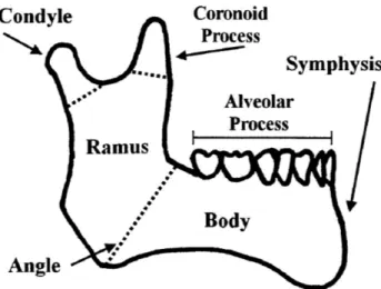
The mandible (lower jaw) is one of the bones that comprise the skull [21]. It exhibits bilateral symmetry accross the sagittal plane. Anatomical regions of the mandible include the body, the angle, and the ramus, as illustrated in the schematic shown in Figure 1-1. Important features include the alveolar process (tooth bearing area), the condyle, the coronoid proces, and the mandibular symphysis ,where the two halves
Condyle Coronoid Process Symphysis Alveolar Process Ramus Body Angle
Figure 1-1: Relevant Anatomical Features of the Mandible
of the mandible join (at the chin). Adult humans normally have 16 mandibular teeth and 16 maxillary teeth.
Mastication (chewing) and speech are the principle functions of jaw activity. Ac-tuation is provided by the masseter, temporalis, pterygoideus lateraliis, and ptery-goideus medialis muscles [21]. During mastication, the mandibular teeth are brought into contact with the maxillary teeth. Each person has a unique pattern of cusps and ridges on the surfaces of their teeth that allow interlocking of the teeth when the jaw is closed. Proper alignment of the teeth, called occlusion, is important for dental well-being.
1.2
Mandibular Fracture
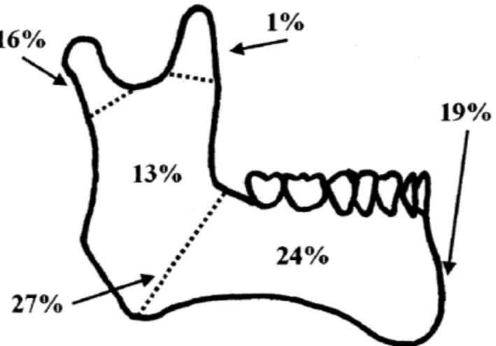
Fracture of the mandible is one of the most common injuries to patients who suffer facial trauma. Roughly 50% of patients admitted to the hospital with facial trauma require surgery to repair a fractured mandible [1, 10, 11, 12, 24, 29]. Almost 75% of mandibular fractures occur in males, most frequently those of age 20-30 [10, 26]. Assault is the most common cause for these injuries; other reasons include motor vehicle accidents, falls, and sports-related injuries [7, 10, 11, 14, 24, 26, 29]. Fractures can occur anywhere in the mandible, but certain patterns of injury predominate. The
16%
19% 13%
24%
27%
Figure 1-2: Fracture Occurance for Different Regions of the Mandible
most common sites of fracture, as shown in Figure 1-2, are at the mandibular angle and mandibular body [10, 14].
A study of the cross-sectional geometry of the mandible can help to elucidate why
this bone is susceptible to fracture. During mastication, forces are applied to the superior face of the bone through teeth at the alveolar process. However, if a person is assaulted, falls, etc., forces on the jaw are usually applied along the lateral face. Figure 1-3 shows a typical cross-section view of the mandible.
Cortical Bone Cancellous Bone Mandibular Canal Alveolar Process Width Height
Adult males typically have a mandible height averaging between 27.6-31.0 mm, and width between 10.5-15.8 mm, resulting in an average aspect ratio of 2.3 [35]. If the cross-section of the mandible is modeled as a rectangle, then Equation 1.1 can then be used to calculate the relative area moments of inertia for each loading condition [17].
I=
-(width) * (height)3 (1.1)12
If strength is defined as the maximum resultant bending stress prior to fracture in the bone, then the strength of the mandible when loaded on the lateral face is roughly
18% of that when loaded as in mastication. Thus, the mandible is very susceptible
to fractures when loaded laterally.
1.3
Repair Techniques
Surgical repair of mandibular fractures is the most effective method of restoring nor-mal anatomy. The goals of a mandibular fracture repair include: 1) the recovery of pre-injury jaw structure and 2) restoration of normal function. In order to recover the proper structure, it is necessary to restore proper occlusion; this is best achieved through a solid bony union at the fracture site [11]. Restoration of function is favored
by preventing infection and by a suitable period of immobilization [11].
Two strategies are commonly used to immobilize mandibular fractures: closed reduction and open reduction [11, 13]. In a closed reduction, the fracture site is not surgically exposed; rather, the mandible is set in place against the maxillary teeth (upper jaw) [16]. This technique, called Maxillo-Mandibular Fixation (MMF), is usually accomplished by wiring the jaw shut, as shown in Figure 1-4. An advantage of MMF is that the upper jaw effectively acts as a cast for the mandible, aiding the surgeon in properly aligning the fracture halves [16]. However this technique requires the jaw to be immobilized for a number of weeks, which is uncomfortable for patients and complicates other factors such as nutritional intake, oral hygiene, and speech [11].
Figure 1-4: Maxillomandibular Fixation (MMF) Using Arch Bars
These days, open Reduction with Internal Fixation (ORIF) is another strategy used to achieve mandibular fixation [15]. Open reduction means that the fracture site is surgically exposed for access. Internal fixation refers to metal plates that are affixed directly to the bones by way of metal bone screws. These metal plates align the fracture site and provide fixation during the healing process. Figure
1-5 shows a bone plate after placement in an ORIF procedure. Because stability is
provided by the plate, rather than fixation against the maxillary teeth, it is not necessary for the patient's jaw to be immobilized and generally does not require an external incision. Advantages of this technique include better oral hygiene during the healing process, ease of maintaining good nutritional intake, reduced risk of nerve damage, and maintaining the ability to communicate. For these reasons, ORIF with bone plates is currently the preferred method of treatment for mandibular fractures
[1, 4, 5, 11, 12, 15, 36].
Figure 1-5: Bone Plate Used in an Open Reduction Internal Fixation Procedure (ORIF) [16]
1.4
Bone Plates
Many different types of bone plates currently exist and are used in surgery today. There are also various different techniques for applying these plates [1, 4, 5, 9, 11,
13, 15, 20, 25]. In its most basic form, a bone plate is a thin piece of metal, typically
titanium, that is affixed to the bone with screws. Plates generally have a thickness on the order of millimeters; actual dimensions vary by manufacturer. Figure 1-6 shows the geometry of a typical bone plate. Depending on the repair technique used, screws can be placed through one cortical layer (monocortical fixation) or through both cortical layers (bicortical fixation). A single plate may be used or may be used in conjunction with multiple other plates in order to provide added stability.
Holes for Fixation
Figure 1-6: Typical Mandibular Bone Plate Geometry
1.5
Malocclusion
Mandibular fracture repairs, while generally effective, can sometimes suffer from a number of complications. Some of the common complications that can occur with ORIF repairs of mandibular fractures can include [6, 13, 15, 29]:
1) Nonunion of the fracture site
2) Malocclusion of the fracture site
3) infection of the repair site 4) Nerve damage
5) Bone plate failure
improper contouring of the bone plate, improper placement or plate failure. A mal-occlusion occurs when there is displacement of the fracture site during healing [31]. The resulting misalignment of the teeth can cause significant discomfort and make
mastication difficult for the patient. Figure 1-7 shows an intraoral picture of a severe malocclusion resulting from fracture.
Figure 1-7: Malocclusion [6]
Malocclusion is difficult for a physician to objectively assess, but is easily noticed
by the patient. A malocclusion as small as 5 microns can cause discomfort, leaving
surgeons little room for error during ORIF. These small disturbances in the occlusal relationship cannot be detected by x-ray or "bite paper," but can still cause significant discomfort [28]. This places significant demands on surgeons, and the bone plates they use to treat patients, to perform as expected [33, 22].
Roughly 18% of patients who undergo treatment for a mandibular fracture suffer from malocclusion; this most often occurs in patients with associated fractures of the mandible or midfacial region [13, 31]. Malocclusion can be caused by improper placement of bone plates by the surgeon. It can also occur by loosening of the plates and/or screws after surgery [6, 5]. Treatment options for malocclusion include MMF with physical therapy, orthodontics, or further corrective surgery [5, 31].
Chapter
Mandibular Bone Plate Design
2.1
Design Features
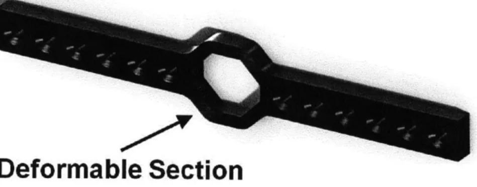
The bone plate design is intended to decrease incidents of malocclusion by giving surgeons more control over alignment after the screws have been placed. This added functionality is accomplished by the addition of an octagonal deformable section to the middle of the bone plate as shown in Figure 2-1. It is expected that this plate can be used with either traditional or locking screws, monocortical or bicortical fixation, and with normal (as opposed to lagging) screw fixation [33].
Deformable Section
Figure 2-1: Mandibular Bone Plate With Deformable Section
The surgeon has the ability to manipulate the deformable section and adjust the alignment between the fractured ends of the mandible until malocclusion is minimized. Deformation will be effected by tool with a variable mechanical advantage, similar to
a pair of Vicegrips. This will allow a surgeon to accurately manipulate the plate by hand, discussed further in Section 2.2.1. Various modes of deformation are shown in Figure 2-2.
0 0 ~ ~ 0 (C" 0 0 C
Oii
0_ -- 0 0oC
Figure 2-2: Variations Modes of Plate Deformation [22]
An octagonal geometry was initially prototyped, and a number of different ge-ometries were considered including square, circular, and rectangular, as seen Figure
2-3 [22]. Diffrent geometries can be used depending on the location of the fracture
and the repair technique of the surgeon.
2.2
Analysis
Functionality of this bone plate depends on the ease with which it can be manipulated
by the surgeon. In order to optimize the design, models were created to find the
stress and deformation resulting from applided load as a function of material and geometric parameters. Two models were used: first, a closed-form solution was found using beam theory, and then numerical model was then created. The results were then compared with an experimental evaluation. The findings of these investigations determined the best model to use for predicting behevior of the deformable section.
2.2.1
Beam Theory
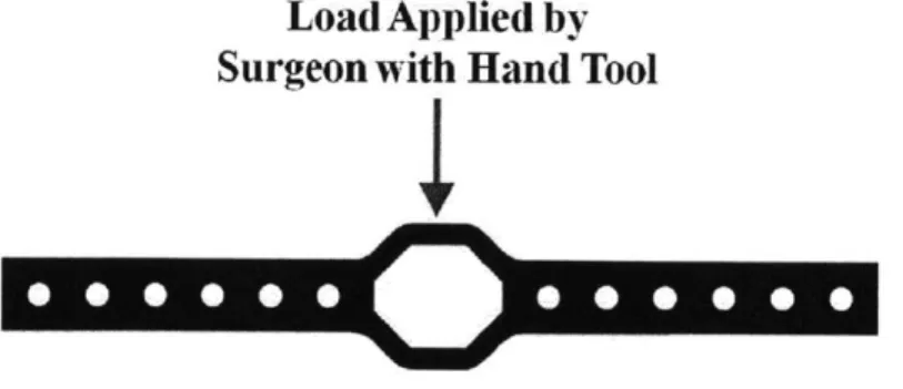
During surgery the deformation of the bone plate would be caused by applied load at the deformable section. The forces required to achieve the necessary deformation dictate the type of tool needed to apply such a load. An example of this loading condition is shown in Fig. 2-4. Given this scenario, beam theory can be used to find a closed-form solution for the force needed to achieve the desired deformation.
Load Applied by
Surgeon with Hand Tool
Figure 2-4: Load Applied to Bone Plate by Surgeon to Manipulate Deformation
Four different beam models were simulated for the loading condition shown in Figure 2-4. These are simple loading configurations for which exact solutions can be found using solid mechanics. Additionally, superposition applies, so results can easily be summed to find an estimate for stress and displacement. Table 2.1 shows a schematic of these loading configurations as well as the equations for maximum
stress and displacement in each beam. These equations were compiled into a Matlab
[27] script to calculate the force necessary to achieve yield stress, and the resulting
deformation. Appendix A contains the script that was used.
Table 2.1: Beam Bending Equations Used to Calculate Stress and Displacement [17]
2.2.2
Numerical Analysis
A numerical study was conducted on the bone plate in order to determine the accuracy
of the analytical model. Simulations were run using a SolidWorks Simulation[8] study. The meshing capabilities of this program allowed for the exact geometry of the bone plate to be simulated, rather than the simple beam approximation used in the closed-form model. Figure 2-5 shows the mesh of 56,564 4-node elements that was created.
Figure 2-5: SolidWorks Simulation Mesh of 56,564 4-Node Elements
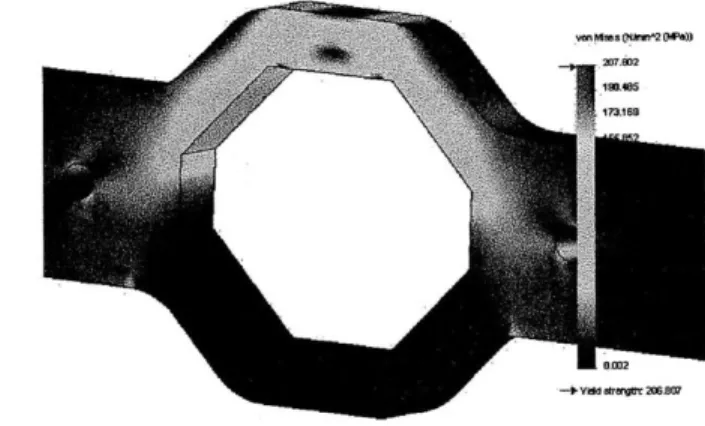
Two types of loading conditions were applied: concentrated center loading and distributed loading. Figure 2-6 depicts the deformation and stresses for a concentrated load applied to the bone plate. This loading condition results in a large deformation at the site of load application, with high stress concentrations at the point of load application, and minimal stresses in other regions.
Figure 2-6: FEA Central Loading Results
A distributed loading condition was also simulated. Figure 2-7 shows the
defor-mation and stresses for this configuration. The stresses are distributed over a much larger area than in the previous configuration, and the deformation is much smaller.
Figure 2-7: FEA Distributed Load Results
The results from the numerical analysis can be used in conjuction with the closed form analysis to predict the forces needed to deform the center section of the bone plate. Variations in the geometry of the bone plate can be taken into account so that the proper tooling can be developed for each embodiment of the plate. Numerical analysis is especially useful for predicting the deformation in irregular geometries that are difficult to model analytically.
2.2.3
Experimental Evaluation
Behavior of the plate was tested experimentally in order to compare results from the analytical and numerical modeling. A static testing jig, shown in Figure 2-8, was built to constrain vertical translation and rotation about the long axis so that testing loads could be applied to the center deformable section. The jig was milled out of aluminum stock at the MIT Hobbyshop. Most commercially available bone plates, such as those manufactured by Synthes [34], are made from titanium alloy. However, bone plates for this stage of testing were fabricated using 304 stainless steel cut with a waterjet. This was deemed an acceptable substitute because the goal of the testing was not to predict in vivo performance, but rather to validate the analytical and experimental models.
Figure 2-8: Deformable Bone Plate in the Static Testing Jig
An Instron machine [18] was programmed to apply testing loads to the bone plate at a rate of 1 mm/sec until a displacement of 5mm was achieved. A total of 4 bone plates were tested. Force and displacement data, shown in Figure 2-9, were recorded for the duration of each trial. Only one side of each bone plate was tested. However, in future testing it may be possible to use both sides of the plate. Numerical modeling can be used to determine if stresses experienced on the other side will cause plastic deformation.
i600
-Region iRegion Region
1400 - 1 23 1200 -'00 - Trial 1 ano - -- Trial 2 Trial 3 200 -Trial 4 -0 1 12S aC 3 4 5 6 2 Displacement (nMn)
Figure 2-9: Load Testing Results
The experimental data show similar qualitative trends for each trial; three distinct regions are evident. Elastic behavior is initially seen in Region 1, followed by a transition to plastic behavior at -0.4 mm. In Region 2 displacement continues with
minimal increase in load. Finally, after -3.25 mm of displacement an increase in force is needed to produce further deformation in Region 3. Figure 2-10 shows the progression of deformation in each of these regions.
Reg ion 1
Reogion 2
3.5 4
Region3
Figure 2-10: Progression of Bone Plate Deformation Three Loading Regions
(mm, in red) for Each of the
The trend in Region 3 may be a result of the configuration of the experimental setup; an angled attachment, shown in Figure 2-11, was used to apply the load to the bone plate. It is possible that in Region 3 this attachment prevented the central bar of the bone plate from deforming naturally, instead causing the angled sections to bend. A different load applicator can be fabricated for future testing that would
Instron
ngled Edge
Figure 2-11: Attachement Used to Apply Load to Bone Plate
Two distinct groups are apparent in the data that were recorded. Both follow the same trends decribed above, but Trials 1 & 2 are offset by -400 N from Trials
3 & 4. This discrepancy may have been caused by differences in the placement of
the testing jig relative to the Instron machine, differences between the placement of the bone plate in the testing jig, or strain hardening in the load applicator. Future testing can incorporate a kinematic coupling such that the testing jig is always placed on the Instron stage in the same position. Regardless, more bone plates need to be tested in order to produce statistically significant data.
2.2.4
Results
Deformation of the center section of the bone plate was modeled using beam theory and numerical simulations. These models were then compared to results from ex-perimental evaluation. The material properties of 304 stainless steel, shown in Table 2.2.4, were used in the analytical and numerical models.
Table 2.2: Material Properties for 304 Stainless Steel
Value Units Modulus of Elasticity 109 GPa
Poisson's Ratio 29 N/A
The analytical and numerical simulations were programmed to determine the force and resulting displacement necessary to produce yielding in the bone plate. Values from the experimental evaluation were determined from the Force-Displacement plot in Figure 2-9. A comparison of the results from the analytical, numerical, and exper-imental methods are shown in Table 2.2.4.
Table 2.3: Force Required to Achieve Yield Stress in the Bone Plate: Comparison of Results from the Analytical, Numerical, and Experimental Models
Model Loading Condition Force (N) Displacement (mm)
Cantilever Concentrated 122 0.0282 Numerical Concentrated 345 0.0082 Numerical Distributed 351 0.0082 Experimental, N/A 358.8 0.1349 Trials 3-4 Fixed-Fixed Concentrated 487 0.0252 Experimental, N/A 791.6 0.3023 Trials 1-2 Cantilever Distributed 973 0.0429 Fixed-Fixed Distributed 1459 0.656
Both numerical simulations predict similar forces and deformations. However, the deformation of the simulation using a concentrated loading condition, shown previously in Figure 2-6, is a closer match to the deformation seen in experimental evaluation. Thus, it can be shown that a concetrated loading condition isthe best option for future numerical studies.
The analytical model using a fixed-fixed beam with a concentrated loading con-dition was the closest match to the experimental results. This model matched the force data from experimental trials 3 & 4 with 26% percent error and the results from trials 1 & 2 with 38% error. Differences between the analytical model and experimental model can be attributed to geometry approximations and compressive deformations which were not accounted for. Future versions of the analytical model could incorporate these assumptions.
Displacement calculations of the analytical models differed from the experimen-tal results by an order of magnitude; numerical calculations differed by 2 orders of
magnitude. These differences could be the result of isotropic and small-deformation approximatons used in the numerical solver and inherent in the Euler-Bernouilli beam bending equations. Large deformation assumptions could be used for future versions of these models.
Experimental results show that a force between 350 and 800 N is needed to deform the bone plate. If the average human hand strength is taken to be close to 177.9 N (40 lbs), then the tool to be used to deform the bone plate must be capable of a mechanical advantage between 2 and 4.5 at its end effector. The analytical and numerical models discussed previously can be developed further to accurately calculate the forces needed to deform different embodiments of the bone plate.
Chapter 3
Testing Apparatus
The bone plate described in Chapter 2 is designed to achieve internal fixation for mandibular fracture repairs while giving surgeons control over the occlusal relation-ship between fracture halves. In order for this new technology to be adopted by oral & maxillofacial surgeons, the strength of this plate must equal or exceed existing plates, and its must possess the functinality to easily and sufficiently control the occlusal relationship. Thus, there are two parameters which must be tested in order to assess the performance of the bone plate: 1) strength and 2) usability.
This work focuses on the design of a testing dynamic apparatus to evaluate the strength of the bone plate relative to other plates. The motivation for choosing this approach was to prove the new bone plate design as a viable option to existing plates. Future work will focus on evaluating the usability aspects of the plate.
3.1
Design Process
A deterministic design process was followed during the design process for the testing
apparatus. This included 1) development of functional requirements, 2) a prior art & literature revew, 3) strategy brainstorming & selection, 4) concept development, and
3.2
Functional Requirements
The functional requirements for the dynamic testing apparatus design were developed with in input from Dr. Ed Seldin [33] and Alex Slocum, Jr. [22]. Table 3.2 lists these Functional Requirements, which were drawn from the existing body of knowledge to address the scope and needs of the this apparatus.
Table 3.1: List of Functional Requirements
1) Quantify the performance of bone plates in a mandibular configuration
2) Repeatable & consistent testing conditions
3) Adaptable to different plate models
4) Bone plate behavior decoupled from that of the testing mechanism
3.2.1
Prior Art & Literature Review
A number of studies in the literature investigate the behavior of different mandibular
bone plates. A review of these studies reveals different goals and strategies that have been used to perform bone plate testing.
Two important factors that define a strategy for bone plate functionality testing are 1) the mounting substrate and 2) the loading condition. This section focuses on the ways that different studies from the literature have incorporated these factors into their testing strategy.
Mounting Condition
The mounting condition of the testing apparatus is how the bone plate is fixated. In a surgical setting, the bone plate is fixed to mandible itself using screws. Previous studies have used a number of different strategies for mounting the bone plate during testing, including:
1) Human mandible [7]
2) Sheep mandible [1, 24]
3) Bovine rib [3]
4) Synthetic mandible [11, 23]
There are clear advantages to using real bones: the bone plate can be affixed using the same techniques as in surgery. The mechanical properties of the bone are conserved, resulting in testing data that reflects the performance of the plates in vivo. Consistent & repeatable testing is difficult when using real bone. Many bone plates are manufactured with a standard geometry, with the inention that they are reshaped during surgery to fit the specific contours of the repair site. A bone plate of interest would need to be adjusted in this manner in order to accomodate the contours of the bone. This procedure would have to be performed by a skilled surgeon who is well-practiced in the field of mandibular repairs.
Other studies have used synthetic mandibles [11, 23]. Some, such as Sawbone mandibles (Figure 3-1), mimic the goeometry and mechaical properties of bone [30]. They are available with condylar features that facilitate consisent and precise fixation using known anatomoical landmarks. The properties of cortical and cancellous bone are approximated by using different composites in the cross-section of the model.
Figure 3-1: Sawbone Mandible [30]
Synthetic mandibles have certain advantages: the cost of each mandible can be significantly reduced; Sawbone mandibles range from $20-$70 [30]. Also their
goeme-try is consistent, providing a standard configuration for each test of the bone plate. Handling of synthetic mandibles is much less logistically intense, as they do not re-quire cleaning or freezing.
Loading Condition
The literature has shown that the human masseter muscles are capable of forces from
300N-400N for the average healthy male [9]. However, other studies have shown that
patients have a post-operative bite force between 60N and 200N, with an average of
150N [20]. This is most often due to the trauma associated with surgery and muscle
soreness due to hyperextension of the mandibular joint for some patients. Based on these data an optimal testing load is between 50N and 400N.
Many studies in the literature use a cantilever loading condition, with the force applied at the incisors [9, 26, 11], the anterior molar region [20] or in a unilateral molar clench [26, 25]. Others use a three-point bending configuration with the center load at the fracture site [1]. These two loading conditions are shown in Figure 3-2.
0 0 0 0 0 0 0 00 1
0000 0 0"i 00 000 (2)
Figure 3-2: Possible Loading Conditions: Cantilever (1) and Three-Point Bending (2)
Some studies have tested in uniaxial tension [32], but this loading condition is not relevant for the present reesarch because it is not representative of the forces experienced in vivo. Based on previous studies it would be optimal to have a test-ing apparatus that could simulate loads at each of these sites. Of these options,
three-point loading at the fracture site is most preferred because it is independent of mandible geometry.
Standards
Standards for bone plate testing have been published by ASTM international and the International Organization for Standardization (ISO). ASTM standard F382 [2] and
ISO standard 9585 [19] describe a testing strategy that uses dual rolling supports to
mount the bone plate, and a four-point loading condition. A significant advantage of this strategy is that the behavior of the plate is isolated from the mounting supports. Consistent & repeatable testing for a variety of bone plates can be easily achieved. Schematics of these standards are displayed in Figure 3-3.
* F 2 - (2O ' k12 k Appi ec Loa d A--, SLupport Po~ers 7 Section A- A
ASTM-F382
ISO-9585
Figure 3-3: Testing Apparatus Conforming to ASTM-F382[2] and ISO-9585[19]
3.2.2
Strategy Selection
After reviewing the prior art & literature, several strategies, listed in Table 3.2.2, were developed to address the functional requirements.
Real bone is a good choice for predicting the performance of bone plates in vivo, but is not suited for this research because it does not allow for repeatable conparisons
Table 3.2: List of Design Strategies
1) Real bone
2) Synthetic bone, mandibular shape
3) Synthetic bone, other shape
4) Simply supported, three-point loading on lateral face
5) Simply supported, three-point loading on superior face
betweeen bone plate designs. Repeatedly reshaping the bone plate in as described in Section 3.2.1 drastically reduce the repeatability of results obtrained using the testing apparatus. The plate behavior would not be isolated from the behavior of the bone because they are rigidly attached.
Synthetic bone in the shape of a mandible would still require custom reshaping of the bone plates, reducing the repeatebility of testing results. Furthermore, the results would be less applicable to in vivo performance than using real bone, and behavior of the plate is not isolated from the substrate.
A synthetic bone substrate can be made into a variety of configurations. Figure
3-4 shows a sketch of a strategy in which the bone plate is mounted to simple beams. When loaded, the beams move such that the behavior of the plate is isolated from that of the beams. This configuration allows for repeatible testing, but may be difficult to use with deformed plate geometries.
The simply supported mounting technique described in the ASTM and ISO stan-dards provides a setup that is easily repeatable for a variety of plate geometries. The plate is not affixed to the apparatus, meaning that the plate behavior is isolated from that of the apparatus. However, the load is applied normal to the lateral face of the bone plate. This is not analogous to the forces experienced by bone plates in vivo. This strategy is sufficient to compare different bone plates against each other. How-ever, the results would not lead to significant insight regarding the use of the bone plate in a practical setting.
An in vitro testing setup could be created if a load is applied to the top surface of a simply supported plate, rather than the side. This configuration would allow for repeatable testing results, and also give insight into in vivo performance. A possible disadvantage, however, is that testing plates with deformed geometry may be difficult. These strategies were compared using the Pugh chart shown below in Table 3.2.2. The ability of each strategy to accomplish the Functional Requirements was weighted, and compared with a datum.
Table 3.3: Pugh Chart Evaluation of Design Strategies
Design Strategies
Functional Requirements 1 2 3 4 5
Quantify Performance 0 0 -1 -2 -1
Repeatable 0 +1 +3 +2 +2 Different Geometry 0 0 +1
+2
+2 Isolate Plate Performance 0 0+1
+1 +1TOTAL 0
+1
+4
+3
+4
The two highest scored strategies were 3 and 5: synthetic bone configured to isolate plate behavior from the testing apparatus, and three-point loading on the superor surface of the bone plate. The next step in the design process was to develop concepts to implement these strategies.
3.2.3
Concept Design
Two testing concepts were developed based off of the results from the Pugh Chart evaluation in Table 3.2.2. Concept 1, shown in Figure 3-5, uses a synthetic mounting substrate to affix the bone plate in a mandibular configuration. The bone plate is mounted on two plates with rounded ends that are initially in tangential contact. These mounting plates are then affixed to grounded columns using single fixed-pin joints. The testing load is applied with a roller at the center of the configuration, resulting in three-point bending at the fracture site. An Instron machine [18] can be used to apply the necessary loads and record data.
Figure 3-5: Testing Concept 1
The simplicity of this design allows for consistent & repeatable testing conditions that can be applied to a variety of bone plate geometries. The configuration of the mounting arms decouples the performance of the plate from that of the testing apparatus. As displacement increases, the rounded edges of the mounting plates roll against each other, pivoting about their mounting axes. The attachment at the mounting columns allows for unrestricted horizontal translation, as shown in Figure
3-6. This eliminates any bending, and thus concentrates all of the moment on the
Horizontalsliderallows unconstrained translation
Initial tangential contact between mounting arms
Figure 3-6: Concept 1 Mounting Arms in Tangential Contact
Concept 2, shown in Figure 3-7, applies a three-point bending load to the plate in a mandibular configuration. The bone plate is placed in the central channel and rests on two pins. A testing load is then applied to the center section. The channel keeps the bone plate in the proper orientation as it is being deformed. This concept is similar to the ASTM and ISO standards mentioned previously; however, the crucial difference is in the orientaiton of the bone plate during testing.
LoadAppliedHere
Pin Support Contacts
3.2.4
Risks & Countermeasures
Potential risks were assessed for Concepts 1 & 2, and countermeasures were then identified to mitigate their effect on performance. The most critical module of both concepts is their ability to isolate the behavior of the plate from that of the testing.
A risk for this MCM is that misalignment could create parasitic forces between the
plate and the testing apparatus, preventing collection of data that is accurate and precise.
The testing load in Concept 1 is applied at the centerline of the bone plate. A parasitic moment is created if the centerline of the bone plate is not in line with the centerline of rotation of the mounting arm. A possible countermeasure is to affix the bone plate such that these centerlines are in line with the testing load. Figure 3-8 illustrates this risk and countermeasure.
-F.
Centerline of Mounting Arni Rotation
I I
ParanielinmetedCountermieasure
Shaft misalignment could also cause parasitic moments in Concept 1. The shaft of the mounting arm is set within a bearing. The arm will tilt undesireably if the gap between the shaft and the bearing is too great, as shown in Figure 3-9. The centerline of the bone plate will then be offset from the point of load application, resulting in a parasitic moment. Analysis of this error motion shows that this gap must be less than 0.0197" in order to have an offset that is less than 1% of the bone plate height. A greater tolerance can be allowed if the length of the shaft in the bearing is increased. Calculations are shown in Appendix B.1.
F
Bearing
ParasiticMoment =F*A A
Cross-section of bearing block Cross-section of bone plate
Figure 3-9: Shaft Misalignment Risk for Concept 1
Parasitic forces in Concept 2 could be generated if the central channel is too large, causing a tilt in the bone plate orientation as shown in Figure 3-10. Analysis of this error motion shows that the central channel must be machined to a tolerance of
0.0025" to have a parasitic force that is less than 1% of the applied load. Calculations
are shown in Appendix B.2. This tolerance can be achieved by milling the channel out of a solid block of aluminum, as opposed to assembling the apparatus from separate parts. A 1/16" endmill must be used for this process; this requres a feed rate of 0.25 in/min at depth increments of 0.020" to ensure that the endmill does not break.
Figure 3-10: Tolerance Risk for Concept 2
3.3
Testing Protocol
Performance of the bone plate will be evaluated using the dynamic testing apparatuses described previously. Testing bone plates of differing geometries while keeping the material properties constant will give insight into the performance of the new bone plate relative to those currently used by surgeons.
Bending stiffness and force to failure will be the metrics used to evaluate relative performance of the bone plates. Bending stiffness is a standard of measurement spec-ified in ASTM-F382, and is calculated by finding the slope of the linear elastic region of the force-displacement curve [2]. Plates with different geometries will have differ-ent bending stiffnesses; therefore this parameter can be used to compare performance between different bone plate embodiments. Force to failure will be measured by in-creasing the testing load until the bone plate fails. This parameter has been measured in the literature [20, 23], and will provide further comparison between different bone plates and prior studies from the literature.
Four different testing trials, showin in Table 3.3, will be performed. The first trial will establish a baseline by testing a plate with standard geometry, similar to that in Figure 1-6. The second trial will evaluate the performance of the new bone plate in
its undeformed state. The third trial will evaluate plates that have been deformed
by Dr. Seldin such as they would be during surgery. The plates for trials 1-3 will
be fabricated by cutting 304 stainless steel on a waterjet. The same material will be used so that the results can be compared against each other. Finally, a fourth trial will be conducted using currently available bone plates. Results from this trial can be qualitatively compared to those from trials 1-3. Furthermore, the findings from trial 4 can be used to relate the work of this protocol to other studies found in the literature.
Table 3.4: List of Testing Trials
Trial Bone Plate Type Deformed Y/N Material 1 Standard geometry N 304 SS
2 New bone plate N 304 SS 3 New bone plate Y 404 SS 4 Currently available N Titanium
Chapter 4
Conclusions & Future Work
Malocclusion is a painful condition that can result from complications during mandibu-lar fracture repair. A new bone plate design with a deformable region has been in-troduced with the intent of providing surgeons with a tool to help reduce the risk of malocclusion by enabling adjustment of fracture alignment after plate fixation.
A surgeon would use the new bone plate by applying a load to the deformable
center section until the desired shape is achived or observed alignment at the fracture site is improved. This load was predicted using beam theory models and numerical simulations. A testing jig was built to evaluate the deformation of the bone plate during loading. It was determined that a load between 350 N and 800 N is necessary to achieve deformation in the central section of the bone plate. This was most accurately predicted using a fixed-fixed beam model and a numerical simulation, each with a concentrated center load.
Performance of the bone plate was assessed through the design of an in vitro testing apparatus that simulates mandibular fixation and loading conditions. Two concepts were developed; one uses a synthetic mandible substrate to affix the bone plate in a configuration such that the performance of the plate is decoupled from that of the testing apparatus. The second concept, based off of ASTM and ISO standards, applies three-point bending to the bone plate while constrained in a mandibular configuration. These testing apparatuses differ from others found in the literature because they allow for consistent & repeatable testing for a variety of bone plate geometries, while
maintaining mandibular orientation. The goal of these testing methods is not to predict in vivo performance, but rather to provide a platform to reliably compare different bone plate performances against each other.
Future work will include further design iterations and fabrication of the testing apparatuses described in Section 3.2.3. Further numerical simulations can be created to predict bone plate performances in these apparatuses, and also to better predict the deformation of the center section. The beam models can be developed to include large deformation assumptions in order to more accurately predict the forces needed to deform the bone plate. Once the testing apparatuses are built, bone plates of various deformed geometries will be tested in conjunction with Alex Slocum, Jr. and Dr. Ed Seldin.
Appendix A
Beam Theory Matlab Script
%% Written by: Thomas Cervantes
%% Last modified: 5/10/11
function [ = BeamModels()
%% Calculates force needed to acheive specified yield stress
%% Also calculates displacement
%% Models used:
%% Fixed-Fixed, Concentrated center load
%% Fixed-Fixed, Distrbuted load
%% Cantilever, Distributed load
%% Cantilever, Concentrated load
clear all
clc
%% Define geometry of the beam t = 0.00201; %% thickness (m)
w = 0.00203; %% width (m)
L = 0.004699; %% length (m)
%%Calculate 2nd area moment of inertia I = (t*w^(3))/12; 7/m^4
%% Define material properties of beam
E = 190000000000; % Modulus of Elasticity for AISI 304
%% Initialize Parameters Forcel = 0; Stress1 = 0; Disp1 = 0; Force2 = 0; Stress2 = 0; Disp2 = 0; Force3 = 0; Stress3 = 0; Disp3 = 0; Force4 = 0; Stress4 = 0; Disp4 = 0;
%% Define step size for force increment
dF = 1;
%%%%%%%%%%%%%%%%%%%17%%%%%%%%%%%%%%%%%%%%%%%%%%%%%%%%%%%%%%%%%%%%%%%%%% % Scenario 1: Fixed-Fixed + Cantilever Beam; Concentrated Point Load %
while Stress1 < YieldStrength
P = Force1(end) + dF;
Forcel = [Forcel; P];
%%Calculations for Element 1: Fixed-Fixed Beam with Concentrated Load at Center
R1 = P/2; % Reacton force at fixed end
M1_max = (P*L)/8; %Maximum moment at fixed ends
Mlcmax = (P*L)/8; %Maximum moment at center
d1_max = (P*L^3)/(192*E*I); XMaximum displacement
sigma1_cmax = (M1_cmax*(w/2))/I; %Maximum bending stress at center in Element 1
%%Calculations for Element 2A: Cantilever Beam with Concentrated Tip Load P2 = R1*sqrt(2)/2; %Bending force on Element 2 from reaction force
d2Amax = (P2*L^3)/(3*E*I); XMaximum displacement
%%Calculations for Element 2B: Cantilever Beam with End Moment M2Bmax = Mimax; %Maximum moment (constant across length) d2Bmax = (M2Bmax*L^2)/(2*E*I); %Maximum displacement
%%Final Calculations (stress, dtot)
zuemeovldsTp mnmTx-eW% ! (1*3*8) / (V_ (Z/1) *d) = x-em-Tp
(pue pexTj zv) zuemom mnmTx-eW % !Z/(Z_(Z/q)*(Z/d)) = x-em-Tw pug pexi; 4p goao; uozo-ead % !Z/q*d = Td m ppol pgznqTazsia MaO;TUfl lq4TM Ure9S a9A9TTZTMD :T Zu9m9T3 %%
!q/d = d
![d !C90-10J] = E9DaOJ
!JP + (Pu9)E9OaOJ = d
qz2uqazspTqTA > esseazs 91Tqm
%%%%%%%%%%%%%%%%%%%%%%%%%%%%%%%%%%%%%%%%%%%%%%%%%%%%%%%%%%7070%%%%%%%%%%
7PVOI 9amss9ad p9znqTazsiG !Me9S a9A91TZUeo + a9A9TTZTmD :C OlaeuOoS % %%%%%%%%%%%%%%%%%%%%%%%%%%%%%%%%%%%%7171%%%%%7171%%%%%%%%%%%%%%%%%%%%7171%%%
pug ![xemo-Tvm2Ts !Zsseazs] = zssaazs
![(xPm-gZP + xem-VZP)*(Z/(Z)Zabs) + x-em-TP !Zdsia] = Zdsia
suOTTeTnOT-eD Teuld %%
zuamgo-eldSTP mnmTxeW% = x-em-SZp
(iqz2uel ssoao-e zimzsuoo) 4u9mom mnmTx-eN% !x-em-TW = x-em-SZH zugmoN pailddV iq4T4 ureag a9AOITZIMO :SZ 4U9UI9TH %%
Zu9m9D-eTdsTp mnmix-eN% = xmm-VZP
9oao; uoizo-eaa moal Z zuemajZ uo eoaoj BuTpueg% !Z/(Z)zabs*T-9 = Zd
pvol dTj pgzpazueouoo 'q4TM M29S 19AOITZU'eo :VZ zu9ta9T2[ %%
aezueo zv sseazs 2uTpuaq urnmTxeN% !I/((Z/m)*xemo-TN) = xmmo-Tvm2Ts
zueme:)-eTds-rp urnm-Ex-eW@/ = Xmm-TP
aezueo zv 4uemom urnmTxeN% !VZ/(Zq*d) = x-emO-TW
SPU9 P9XT; Z7e 4UOMOM MTIMTx-eKo/. !ZT/(Z_-I*d) = x-em-Tlq
pug paxij 4-e eoaoj uozoper/. !z/(q*d) = Td
m pvoq pgznqTazsTa mao;Tull -q4Tm ureeg pexTj-paxTj :T 4ugmgTZ %%
!q/d = d
![d !Z9DaOJ] = Z9DaOJ
!JP + (Pu9)Z93aOJ = d
'qQ2u9aZSPT91A > Zss9aZS 9TT'qm 7171%%%%%7171%%%%%%%%%%%%%%%%%%%%%%%%%%%%%%%%%%%%%%%%%%%%%%%%%%%%%%%%%%%%%%
% VeOl GanssOad pgznqTazsia !MEOU a9A9TT4tMo + P9XTj-p9XTj :Z OTaeU90S%
%%%%%%%%%%%%%%%%%%%%%%%%%%%%%%%%%%%%%%%%%%%%%%%%%%%%%%%%%%%%%%%%%%%%%%%
pug
(((PU9)V93IOJ'(N P% = SUTP19TA OZ 9OaOj,)jZUTads)dsip
((:PVOI P9ZV24U93UOO q4TM T9POM Z9A9TT: TMO,)dSTp
szlnsgd AvIdSTa %%
pug
![Xem-TVUISTS !:Vssgazs] = vsseazs ![(xmm-gzp + xem-vzp)*(z/(z)zabs) + xem-Tp !tdsia] = VdSTG (ZOZP 4SS9aZS) SUOIZeTnOTPO IVUTJ%%
zuemeo-eldSTP OMMIXeK% ! = XeM-SZP
(lqz2uaT ssoao-e ztmzsuoo) ZU9MOM MlntaTx-eW% !xeta-TH = x-em-SZN
ZU9MON Pug 'qZTM UM9U aOA91TZIMO :2Z 47a9m9TH aOJ suOTZVTnDT-eD%%
Zu9m9D'eTdsip mnmTx-eN% = xem-VZP
90-TOJ UOTZDP9a Mal Z ZU9M9121 UO eDIOJ 2UTPU9a% !Z/(Z)Zabs*Td = Zd
p-eol dTj P9ZPaZU90UOD 7qZTM Mega l9A9TTZUe3 :VZ 4U9M9T2[ 20; SUOTZPTnOT-eD%% pug z-e sseazs 2uTpueq ummixeW% !I/((Z/m)*xem-TW) = x-em-T-em2Ts
Zu9m9D-eTdsTp mnmixeiq% = xmm-TP
(pue paxi; zv) zuemom urnmTx-eW % !q*(Z/d) = x-em-Tl#f
Pug PGxTJ 4-e 90aO; uOZDP9d % !Z/d = Td
dTj zv p-eol p9ZVaZU90UOD lqZTM Mega a9A9TTZuPO :T 4u9m9TS aOT suOTZPTUDTvO%%
! Ed *9020J] = V9DaOa
!qP + (Pu9)V9010A = d
'qZ2u9aZSPT9',k > Vss9aZS 9TTqm
%%%%%7171%%%%%%%%%%%%%%%%%%%%7070%%%%%%%%%%%%%%%%%%%%7171%%%%%%Y070%%%%%%%%%% % P-eOq ZuTOd P9Z-eaZu9DuOD !UMOS a9A9jTZU'eD + a9A9TTZueD :t OlaeuODS %
%%%%%%%%%%%%%%%%%%%%%%%%%%%%%%%%%%%%%%%%%%%%%%%%%7171%%%%%%7170%%%%%%%%%%
pug
![x-em-Tem2Ts SsseazS ![(xmm-gZp + xem-VZp)*(Z/(Z)zabs) + x-em-Tp !CdSTa] = CdSTG
suO'ZPTnDT-eO TVUTA %%
zugmeo-eTdsip ummireg = x-em-SZp
(-qz2ual ssoao-e zupzsuoo) zuemom mnmixeW% !xem-TH = xem-SZN zuemoN peTIddV -qzTm ureag a9A9TTZuPD :9Z Zu9m9T3 %% 4uemeo-eldsTp urnmixeN% = Xem-VZP
eoaol uoTzo-eea moal Z zuemalZ uo 9oao; Buipugg% !Z/(Z)zabs*Td = Zd
ppoq dTl pezPazueouoo -ql.Tm ureag a9A9TTzu-eo :VZ Zu9m9TS %% pug zP sseazs SuTpueq tunmTxeN% !I/((Z/m)*x-em-TH) = xmm-Tvm2Ts
disp(sprintf('Displacement = %f mm\r',Disp4(end)*1000))
disp('Cantilever model with distributed load:')
disp(sprintf('Force to yielding = %d N',Force3(end)))
disp(sprintf('Displacement = %f mm\r',Disp3(end)*1000))
disp('Fixed-Fixed model with concentrated load:') disp(sprintf('Force to yielding = %d N',Forcel(end)))
disp(sprintf('Displacement = %f mm\r',Disp1(end)*1000))
disp('Fixed-Fixed model with distributed load:') disp(sprintf('Force to yielding = %d NI',Force2(end)))
Appendix B
Tolerance Calculations
B.1
Analysis for Concept 1
Misalignment at the bearing: sin(9) =
Small angle approximation: sin(O) ~ 0
Misalignment at the center of the bone plate: sin(9) = ,Ahpi ate
It is desired that 2A < 0.01:
hP0 ate
Shaft Misalignment
Given that Lbcaring = 1.987 in, d < 0.0196853675 in .
B.2
Analysis for Concept 2 Gap Misalignment
Tilt in channel:
sin(9) = 26
hpi ate
Relationship between applied force sin(O) = Fparasitic
Fapplied
It is desired that Fparasiic < 0.01
Fapplied
sn(h 2 ) 0.01
and parasitic force:
Bibliography
[1] Alper Alkan, Nukhet Celebi, Bora Ozden, Bureu Bas, and Samet Inal. Biomechanical comparison of different plating techniques in repair of mandibular angle fractures. Oral Surgery Oral Medicine Oral Pathology Oral Radiology & Endodontics, 104:752-756,
2007.
[2] ASTM F382. Standard Specification and Test Method for Metallic Bone Plates. ASTM international, West conshohocken, PA, 2008.
[3] Todd Bredbenner and Richard Haug. Substitutes for human cadaveric bone in
maxillo-facial rigid fixation research. Oral Surgery Oral Medicine Oral Pathology Oral Radiology
& Endodontics, 90:574-80, 2000.
[41 Thomas Chiodo, Vincent Ziccardi, Malvin Janal, and Christopher Sabitini. Failure Strength of 2.0 Locking Versus 2.0 Conventional Synthes Mandibular Plates: A Labo-ratory Model. Journal of Oral & Maxillofacial Surgery, 64:1475-79, 2006.
[51 Byung-Ho Choi, Choong-Kook Yi, and Jae-Ha Yoo. Clinical Evaluation of 3 Types
of Plate Osteosynthesis for Fixation of Condylar Neck Fractures. Journal of Oral & Maxillofacial Surgery, 59:734-737, 2001.
[6] Ricardo Cienfuegos, Carl Cornelius, Edward Ellis, and George Kushner.
Mandible-Special Considerations. http://www.aofoundation.org.
[7] Matthew Craig, Cynthia Bir, David Viano, and Scott Tashman. Biomechanical
re-sponse of the human mandible to impacts of the chin. Journal of Biomechanics,
41:2972-2980, 2008.
[8] Dassault Systemes. Solidworks Simulation, 2010. Used with SolidWorks Student
Edi-tion 2010.
[9] Arthur Dichard and Douglas Klotch. Testing Biomehcanical Strength of Repairs for
the Mandibular Angle Fracture. Laryngoscope, 104:201-208, February 1994.
[10] Ellis E, Moos KF, and el Attar A. Ten years of mandibular fractures: An analysis of 2,137 cases. Oral Surg Oral Med Oral Pathol, 59:120-9, 1985.
[11] FG Fedok, DW Van Kooten, LM DeJoseph, JD McGinn, B Sobota, RJ Levin, and
CR Jacobs. Plating techniques and plate orientation in repair of mandibular angle fractures: an in vitro study. Laryngoscope, 108:1218-24, Aug 1998.
[12] Jose Fernandez, M. Gallas, M. Burguera, and J.M. Viano. A three-dimensional nu-merical simulation of mandible fracture reduction with screwed miniplates. Journal of
![Figure 1-5: Bone Plate Used in an Open Reduction Internal Fixation Procedure (ORIF) [16]](https://thumb-eu.123doks.com/thumbv2/123doknet/13947367.452090/17.918.234.675.793.964/figure-bone-plate-used-reduction-internal-fixation-procedure.webp)
![Figure 1-7: Malocclusion [6]](https://thumb-eu.123doks.com/thumbv2/123doknet/13947367.452090/19.918.234.671.276.557/figure-malocclusion.webp)
![Figure 2-2: Variations Modes of Plate Deformation [22]](https://thumb-eu.123doks.com/thumbv2/123doknet/13947367.452090/22.918.250.670.222.521/figure-variations-modes-plate-deformation.webp)
![Table 2.1: Beam Bending Equations Used to Calculate Stress and Displacement [17]](https://thumb-eu.123doks.com/thumbv2/123doknet/13947367.452090/24.918.138.814.255.650/table-beam-bending-equations-used-calculate-stress-displacement.webp)