HAL Id: inria-00124266
https://hal.inria.fr/inria-00124266v2
Submitted on 7 Sep 2010HAL is a multi-disciplinary open access archive for the deposit and dissemination of sci-entific research documents, whether they are pub-lished or not. The documents may come from
L’archive ouverte pluridisciplinaire HAL, est destinée au dépôt et à la diffusion de documents scientifiques de niveau recherche, publiés ou non, émanant des établissements d’enseignement et de
Solid reconstruction using recognition of quadric
surfaces from orthographic views
Jie-Hui Gong, Hui Zhang, Gui-Fang Zhang, Jia-Guang Sun
To cite this version:
Jie-Hui Gong, Hui Zhang, Gui-Fang Zhang, Jia-Guang Sun. Solid reconstruction using recognition of quadric surfaces from orthographic views. Computer-Aided Design, Elsevier, 2006. �inria-00124266v2�
Solid reconstruction using recognition of
quadric surfaces from orthographic views
Jie-Hui Gong
a,b,∗,Hui Zhang
b,Gui-Fang Zhang
c,Jia-Guang Sun
a,baDepartment of Computer Science and Technology, Tsinghua University, Beijing 100084, P.R.China
bSchool of Software, Tsinghua University, Beijing 100084, P.R.China cSchool of Sciences, Beijing Forestry University, Beijing 100083, P.R.China
Abstract
The reconstruction of 3D objects from 2D orthographic views is crucial for maintain-ing and further developmaintain-ing existmaintain-ing product designs. A B-rep oriented method for reconstructing curved objects from three orthographic views is presented by employ-ing a hybrid wire-frame in place of an intermediate wire-frame. The Link-Relation Graph (LRG) is introduced as a multi-graph representation of orthographic views, and quadric surface features (QSFs) are defined by special basic patterns of LRG as well as aggregation rules. By hint-based pattern matching in the LRGs of three or-thographic views in an order of priority, the corresponding QSFs are recognized, and the geometry and topology of quadric surfaces are recovered simultaneously. This method can handle objects with interacting quadric surfaces and avoids the combi-natorial search for tracing all the quadric surfaces in an intermediate wire-frame by the existing methods. Several examples are provided.
Key words: Solid reconstruction; Wire-frame; Quadric surface; Feature
recognition; Orthographic projection
1 Introduction
Engineering drawings have been employed as a standard language for de-scribing mechanical designs since the 19th century [1] and still plays an es-sential role in engineering practice today. Most existing products are repre-sented by means of engineering drawings. But nowadays, solid modelers have
∗ Corresponding author. Tel: +86-10-6279-5459; Fax: +86-10-6279-5460. Email address: [email protected] (Jie-Hui Gong).
become popular mechanical CAD tools, and solid models are necessary for some computer-aided product development techniques, such as finite-element analysis, process planning, numerically controlled machining, and emulational display. Unfortunately, the information embedded in 2D drawings cannot be directly used in 3D CAD systems. Consequently, the automatic conversion of engineering drawings to solid objects is critical to the maintenance of con-siderable legacy designs and the upgrade of existing products based on their designs.
A body of work related to the reconstruction of solid models from three ortho-graphic views has existed since the 1970’s. In terms of solid representations, existing reconstruction schemes can be basically classified into two major cat-egories: B-rep oriented approach and CSG oriented approach [2,3]. The B-rep oriented approach has one important advantage over the CSG oriented ap-proach, which is reflected in the complexity of the object domain that can be reconstructed. The former can handle more complicated polyhedra and so far has extended the object domain into quadric solid models without restrictions on the axes of curved surfaces. The latter, however, is generally applicable only to mechanical parts of uniform thickness or axis-aligned volumes of revolution, because it typically uses either pre-defined primitives or identifies entities that can be extruded or rotated. The B-rep oriented approach does provide a prac-tical way for automaprac-tically reconstructing mechanical parts from their ortho-graphic views. However, two limitations of existing B-rep oriented algorithms are as follows.
1. The object domain is still restricted since intricate cases of objects with interacting quadric surfaces have not been settled due to the complexity of intersections between quadric surfaces.
2. Long processing time is involved in searching for all the valid surfaces, especially quadric surfaces, in an intermediate wire-frame with the pos-sibility of backtracking and heuristics due to the ambiguity of the wire-frame.
We consider here the natural quadrics, i.e. the sphere, cylinder, cone, and plane, since they are by far the most commonly occurring quadric surfaces used in modeling mechanical parts. The purpose of this paper is to extend the capability and improve the efficiency of the B-rep oriented approach. A novel method is proposed to directly recognize interacting quadric surfaces as well as isolated ones by hint-based pattern matching based on a multi-graph representation of orthographic views. A hybrid wire-frame, which consists of the geometry and topology of quadric surfaces besides vertices and edges, is constructed instead of a conventional wire-frame. This method is able to effectively handle objects with interacting quadric surfaces. And it requires considerably less searching time to extract surfaces by avoiding the combina-torial search that could grow exponentially in complexity.
The rest of the paper is organized as follows. The next section reviews related work focussing on the B-rep oriented approach. Some definitions involved in this paper are then introduced in Section 3. An overview of our B-rep oriented algorithm is presented in Section 4 followed by the details of hint-based fea-ture recognition described in Section 5. Section 6 reports some experimental results of implementation. And in Section 7, a conclusion is presented with a discussion on further development.
2 Related work
2.1 CSG oriented approach
The CSG oriented approach assumes that each object can be built from cer-tain primitives in a hierarchical manner. It tries to construct primitives based on projective entities in orthographic views, and then assemble constructed primitives to form the final solid model using a CSG tree. According to prim-itive construction, the approach can be categorized into two subclasses. The first one, known as the pattern-guided method, interprets the views base on pattern recognition where the patterns being searched for are projections of pre-defined solid primitives [4,5]. Aldefeld’s method [5] is restricted to objects of uniform thickness. The other subclass, known as the volume-cut method, selects 2D loops as bases and uses extrusion (e.g. [6–8]) or rotation (e.g. [9– 11]) to construct 3D primitives. The two-stage extrusion method proposed by Shum et al.[8] can handle objects with 2.5D elements. Soni’s method [9] can construct axis-aligned volumes of revolution that are limited to isolated cases. Lee et al.[10] proposed a hint-based method to generate interacting axis-aligned volumes of revolution. Dirmi et al.[11] adjusted the identification of loops for handling sectional views.
2.2 B-rep oriented approach
The B-rep oriented approach was first proposed by Idesawa [12] and was for-malized by Markowsky and Wesley [13,14]. This approach is based on the idea of constructing an intermediate wire-frame and typically involves the following four steps.
(1) Transform 2D junctions to 3D vertices. (2) Generate 3D edges from 3D vertices. (3) Construct 3D faces from 3D edges. (4) Form 3D objects from 3D faces.
Earlier efforts by this approach mainly focused on generating polyhedral ob-jects from their orthographic views (e.g. [13–17]). Since quadric surfaces play an essential role in the description of manufactured mechanical parts, most later research focuses on the reconstruction of quadric solid models (e.g. [18– 23,25–27]) and has extended the object domain that can be handled.
The automatic conversion of orthographic views to 3D curvilinear wire-frames is the pivotal stage of the B-rep oriented approach. Shin et al.[22] established types of vertices and generated different types of edges according to the types of their endpoints by introducing auxiliary vertices and edges. The method requires a large amount of time to preprocess input data in order to ascer-tain all the types of 2D elements in the views. Furthermore, it may fail to correctly reveal match projections when there is more than one 2D element between two junctions in a view. Kuo [23] used five points on projective con-ics to match projections in different views and therefore handled the case of failure by Shin’s method. However, the recovery of conics involves four complex steps and is a time-consuming process. Shin’s and Kuo’s methods can deal with quadric surfaces with the restriction that the axes of curved surfaces must be parallel to the directions of projection. Zhang et al.[24] ex-tended Kuo’s method to handle the cases that no more definite conic types are available from the views, by employing the five-point method to first ob-tain the types of projective curves. However, the method may fail to correctly determine the corresponding relationship between the three projective conics of a 3D conic, since the points arbitrarily chosen on the unknown type 2D curves do not always satisfy the matching relations. Liu et al.[25] proposed a method based on conjugate diameters to generate conic edges. By combining the geometric properties of conics with affine properties, the method removed restrictions placed on the axes of conics by other methods. Unfortunately, it is a complex procedure to employ distinct retrieval techniques of geometric parameters for different types of conics, which involves large amounts of in-tersecting detection and affine transform. The authors proposed an efficient method for reconstructing 3D wire-frame models of curved objects from three orthographic views in previous work [26]. By depth-first tracing the decision trees constructed according to the projective properties of spatial edges, the method reduces the search space for identifying all the projective matches in three orthographic views. Furthermore, by employing the rational B´ezier form of conics, the method simplifies the procedure for generating various types of spatial conics in arbitrary positions.
Almost all of the existing B-rep oriented algorithms use input drawings that are restricted to line segments and conic sections, and therefore cannot handle intersections of quadric surfaces, where higher order curves may arise. By employing pattern recognition, only Gu et al.[27] discussed handling higher order curves resulted from two intersecting cylindrical surfaces whose axes must be parallel to coordinate planes. So far, objects with interacting quadric
surfaces have not been settled due to the complexity of intersections between quadric surfaces, which limits the object domain to be reconstructed.
All the algorithms based on the B-rep oriented approach need to solve another sub-problem, i.e. extraction of valid surfaces from the intermediate wire-frame. Previous efforts to resolve the problem can be grouped into topological and geometric approaches in nature. By employing concepts of graph theory, the topological approach uses only the connectivity information of the wire-frame to derive the face topology [28]. The approach provides a uniform framework to handle all the surface types. However, it cannot completely reconstruct the B-rep model without the geometry of the surfaces. The geometric approach assumes that the types of two adjacent edges and the relationship between them can define a surface equation. The approach is efficient for objects with planar surfaces. However, a curved surface equation derived from two adjacent edges may be ill defined since the edge types do not provide strict restriction on the type of the surface. Once the type of a surface is defined, the exhaustive depth-first search is used to find all the edges on the surface and trace the face loop. Kuo [29] and Liu et al.[30] employed some accelerating techniques to reduce the searching time.
Since all the existing algorithms only use low-level information of adjacency relationship between projected entities, some ghost elements that generally involve redundant and pathological edges may exist in the wire-frame. There-fore, the B-rep oriented approach still struggles in intricate cases of objects with complicated topology of curved surfaces, where long processing time is involved in the search for all the valid quadric surfaces bounding the object with the possibility of backtracking and heuristics.
In this paper, we propose a B-rep oriented algorithm employing a hybrid wire-frame instead of a traditional wire-wire-frame. The proposed method works bottom-up, starting with an incomplete wire-frame of 3D linear edges along with their pairs of terminal vertices generated from 2D lines in each view. Then, quadric surfaces are recognized from the three views by hint-based pattern matching and assembled into the incomplete frame, which results in a hybrid wire-frame. Finally, the B-rep model is constructed by tracing planar surfaces in the hybrid wire-frame. Using our method, we extend the domain to objects bounded by interacting quadric surfaces that intersect in higher order curves, and improve the efficiency by avoiding the combinatorial search to retrieve all the quadric surfaces in an intermediate wire-frame.
3 Definitions and Terminology
3.1 Three orthographic views
By convention, an engineering drawing consists of three orthographic views: a front view, a side view, and a top view. These views are produced by making parallel projections of objects onto three mutually perpendicular planes. In most cases, three orthographic views will be necessary and sufficient to rep-resent any part [31], and furthermore, they can effectively convey geometrical information for solid objects that are bounded by surfaces of plane, sphere, cylinder, and cone.
Among many conventions in engineering drawing, silhouette edges are impor-tant for curved objects. It is a basic tradition to draw silhouette lines and arcs of curved surfaces in projective views. A silhouette entity is artificial, which corresponds to a silhouette edge that lies on only one surface with respect to a special view direction and appears in only one of the three views [18].
3.2 Hybrid wire-frame
A B-Rep model represents an object as a volume contained in a set of sur-faces together with topological information that defines the relationships be-tween the surfaces. In this work, we consider the surfaces of so-called natural
quadrics, i.e. sphere, cylinder, and cone, because they are by far the most
commonly occurring curved surfaces used in modelling mechanical objects. A wire-frame W = (V, E) is the network structure of the corresponding B-Rep model without the geometry and topology of all the surfaces, where V is a set of vertices and E is a set of edges. Accordingly, the edges included in a curvilinear wire-frame may be lines, circles, circular arcs, ellipses, elliptical arcs, and higher order curves.
Definition 1 (Hybrid wire-frame). A hybrid wire-frame HW = (V, E, S)
is the curvilinear wire-frame of a curved object along with the topology and geometry of all the quadric surfaces, where V is a set of vertices, E is a set of edges, and S is a set of quadric surfaces that are unambiguously identified as a connected set of edges, characterized by the type of surface geometry with geometric parameters.
(a) 1 e e3 2 e 4 e 5 e e6 7 e 8 e e9 10 e 1 v 2 v 3 v 4 v v5 6 v 7 v 8 v (b) Line CircleArc L CA Adjacency Symmetry Concentricity Coincidence CA CA L L L L 9 n 8 n 7 n L L L L 10 n 6 n 5 n 4 n n3 1 n 2 n (c)
Fig. 1. (a) Three orthographic views: a front view (top-left), a side view (top-right), and a top view (bottom-left). (b) Planar graph of the front view: all the edges are lines except that e5 and e6 are circular arcs. (c) LRG of the front view: ni is
one-to-one corresponding to ei.
3.3 Graph Representation of Orthographic Views
Many engineering objects have features aligned with natural axes of them-selves, and the set of three standard views contains a maximum degree of concealment and self-alignment [14]. Consequently, one-to-one correspondence between a solid body and a drawing does not always hold in the level of point and line [12].
Previous B-rep oriented algorithms commonly employ planar graphs to repre-sent orthographic views. A planar graph G = (V, E) is the topological struc-ture of a projective view, where each edge in E represents a projective entity containing its geometric information, and each vertex in V represents a junc-tion of projective entities. For example, Fig.1(b) is the planar graph of the front view in Fig.1(a). We propose the link-relation graph (LRG) based on the planar graph to represent higher-level information embedded in the views.
Definition 2 (Link-relation graph). A link-relation graph LRG = (N, A)
is a multi-graph structure of a projective view, where N is a node set, and A is an arc set. Each node in N represents a projective entity, called a link, which is one-to-one corresponding to a unique edge of the planar graph, and is characterized by the type of link geometry with corresponding geometric parameters. Each arc in A describes a mutual relation between two edges in the planar graph, and is identified by the type of relation.
There are six types of nodes in the LRG, i.e. lines, circles, circular arcs, ellipses, elliptical arcs, and higher order curves, with respect to non-degenerate parallel projection. Higher order curves are commonly approximated with poly-lines. The set of arcs in the LRG is essentially a constraint set of links. Besides the basic adjacency information, mutual geometric relations (i.e., symmetry, concentricity, and coincidence) between links within a projective view are often associated with the projections of quadric surfaces and very meaningful for
revealing quadric features. There are four types of arcs in the LRG which are listed as follows.
• Adjacency: indicates that two links have an end in common.
• Symmetry: indicates that two linear links have equal inclinations with the
same link on its two ends respectively.
• Concentricity: indicates that two centric conic links of the same type have
the same center but different radii.
• Coincidence: indicates that two links have the same geometric shape, same
parameters and natural extension of one matches the other, i.e. co-linear re-lation between linear nodes and concyclic rere-lation between nodes of circular arc.
Fig.1(c) shows the LRG of the front view in Fig.1(a). Each node ni is
one-to-one corresponding to an edge ei in the planar graph shown in Fig.1(b), and
all the arcs of adjacency are many-to-one corresponding to the vertices in the graph. There is an arc of symmetry incident with n1 and n3, since they are
both perpendicular to n2. An arc of coincidence joins two co-linear nodes, say
n1 and n8. A coincidence arc incident with n5 and n6 indicates the nodes are
concyclic.
3.4 Quadric Surface Feature
With the term quadric surface feature(QSF), we indicate an isolated quadric surface or a collection of interacting ones which is on the boundary of a part. To avoid enumerating all the possible cases, we define a set of primitive QSFs plus aggregation rules to form more complex instances called composite QSFs.
Definition 3 (Primitive QSF). An isolated natural quadric surface on the
boundary of a part (i.e., a sphere, a cylinder, or a cone) is defined as a prim-itive QSF.
Definition 4 (Circuit). For a primitive QSF, the subgraph of LRG
corre-sponding to each of its orthographic views is called a circuit.
Definition 5 (Basic pattern). The triplet circuits corresponding to
ortho-graphic projections of a primitive QSF is called its basic pattern.
In Table1, the basic projection patterns of primitive QSFs in arbitrary posi-tions are summarized, with all the types of circuits enumerated. The circuit of a sphere in each view is a silhouette of circle. A cylinder or a cone is pro-jected into at least one circuit with conic node(s) no matter which position it is in and at least two circuits with symmetrical linear nodes corresponding to silhouette edges on the surface.
Table 1
Basic patterns of projections of primitive QSFs
Primitive QSF Axis of primitive QSF Front Side Top Type
Sphere — C C C — Parallel to X R C R coordinate Y C R R 1 Cylinder axis Z R R C Parallel to XOY RE RE IR coordinate Y OZ RE IR RE 2 plane ZOX IR RE RE
Inclined IRE IRE IRE 3
Parallel to X T CC T
coordinate Y CC T T 1
axis Z T T CC
Cone Parallel to XOY TE TE IT
coordinate Y OZ TE IT TE 2
plane ZOX IT TE TE
Inclined ITE ITE ITE 3
Different types of circuits: C—circle; R—axis-aligned rectangle; IR—inclined angle; RE—axis-aligned rectangle with two elliptical subtenses; IRE—inclined rect-angle with two elliptical subtenses; CC—two concentric circles; T—axis-aligned trapezoid; IT—inclined trapezoid; TE—axis-aligned trapezoid with two elliptical subtenses; ITE—inclined trapezoid with two elliptical subtenses.
A primitive QSF is seldom isolated in a mechanical part, but in fact several primitive QSFs do mutually interact in most cases.
Definition 6 (Composite QSF). A combination of primitive QSFs that
obey certain aggregation rules, i.e. coaxial adjacency (type I) and spatial in-tersecting (type II), is defined as a composite QSF. It can be expressed as
SC = ∂([
i
(V (SP
i ))), (1)
where SC and SP denote a composite QSF and a primitive QSF, respectively;
∂ is the topological boundary operator that obtains all the quadric surfaces bounding a volume, V is the operator that forms the volume enclosed by a
(a) (b)
Fig. 2. Examples of aggregation rules: (a) coaxial adjacency (type I) of a cylinder and a cone; (b) spatial intersecting (type II) of two cylinders.
Composite QSF Primitive QSF
Circuit
Arc Node
Fig. 3. Class diagram.
In the case of coaxial adjacency (an example shown in Fig.2(a)), a composite QSF is a direct aggregation of two coaxial primitive QSFs that share a bound-ing edge with each other. Whereas in the case of spatial intersectbound-ing (referrbound-ing to Fig.2(b)), a composite QSF is an aggregation of two intersecting primitive QSFs trimmed by the intersection.
Fig.3 shows a diagram of the classes that are defined according to the above concepts.
3.5 Hints of primitive QSFs
The basic patterns are the particular characteristics of projections of primitive QSFs. However, they are likely to be altered due to the interaction of QSFs. First, an intersection that is shared by two interacting quadric surfaces must appear on the boundary of a part. Consequently, the links corresponding to the intersection must arise in three orthographic views, by which the basic pat-terns of the quadric surfaces are trimmed. Besides the degenerate intersections of plane curves, higher order curves resulting from interacting quadric surfaces with intersecting axes are often required by design. In Table2, we summarize the intersections between pairs of the natural quadric surfaces that are con-sidered in this work. Second, silhouette edges on quadric surfaces are likely modified due to the variety of topology resulting in splitting (even removing) silhouette links.
Table 2
Summary of conditions of intersection between pairs of natural quadric surfaces [32,33].
Surface pair Geometric condition Intersection
Plane-sphere All Circle
Plane-cylinder Plane normal perpendicular to cylinder axis
Line
Plane normal unparallel to cylinder axis
Ellipse
Plane-cone Plane normal perpendicular to cone axis
Line
Plane normal unparallel to cone axis
Ellipse
Sphere-sphere All Circle
Sphere-cylinder Sphere center on cylinder axis
Circle
Sphere-cone Sphere center on cone axis Circle Cylinder-cylinder Parallel axes Line
Intersecting axes and equal radii
Ellipse
Intersecting axes and un-equal radii
Space quartic curve
Cylinder-cone Perpendicular axes Space quartic curve
Cone-cone Intersecting axes and un-equal half-angles
Space quartic curve
On the other hand, quadric surfaces of a typical mechanical part are usually created by translation and rotation operations. The presence rule [34] asserts that a feature and its associated operation should leave a trace on the part boundary even when features intersect. That is to say, the minimal
indis-pensable portion of a primitive QSF should be present on the part boundary
unless the feature is completely removed by other intersecting features. Con-sequently, the projections corresponding to the portion should be present in the orthographic views. In this work, nodes in the LRGs that satisfy certain geometric and topological relationships are considered as hints to guide the search for basic patterns. There are three types of hints in the LRG that are taken into account in the proposed method.
un-derside of an isolated cylinder/cone. In the case of composite QSFs, the interaction of the primitives causes the closed conics to be broken down into conic sections. Two nodes of circle incident with an arc of concentricity suggests the undersides of cones.
• Silhouette-hint: A node of circle hints that there is a silhouette of a sphere.
Two linear nodes incident with an arc of symmetry guide to trace the sil-houettes for a cylindrical or conical surface.
• Intersection-hint: A node of higher order curve indicates the intersection of
two cylinders, two cones, or one cylinder with one cone.
In Fig.1(c), for example, circular nodes n5 and n6 incident with an arc of
coincidence may be regarded as both an underside-hint for a cylinder and a silhouette-hint for a sphere. And linear nodes n1 and n3 incident with an arc
of symmetry may be treated as a silhouette-hint about linear node n2 for a
cylindrical surface.
4 Overview of our reconstruction algorithm
The whole procedure of our B-rep oriented algorithm employing a hybrid wire-frame is illustrated in Fig.4. In the input phase, three orthographic views of a mechanical part are input from a neutral CAD file, and geometric entities maintained in the file are considered. In the preprocessing phase, the three views are separated and converted into the corresponding planar graphs, and then each view is transformed from view-based coordinate system to object-based coordinates.
Three steps involved in the reconstruction phase are as follows.
(1) Incomplete wire-frame generation
Based on the planar graphs of the views, 3D linear edges along with their pairs of terminal vertices are generated from the match bounding
boxes of its projections according to the coordinate correspondences, as
described in [26]. Thus, an incomplete wire-frame is constructed in the absence of curvilinear edges.
(2) Hint-based QSF recognition
All the QSFs are identified by hint-based reasoning in the LRGs that are converted from the planar graphs, and the geometric and topologi-cal information of quadric surfaces are recovered simultaneously. Then a hybrid wire-frame is constructed by assembling the quadric surfaces into the incomplete wire-frame. The procedure is described in detail in the next subsection.
(3) Planar surface extraction
es-Drawing import
View segmentation
Hint-based QSF recognition
Planar surface extraction Incomplete wire-frame
generation
Geometric entity filter
View-plane folder Input
Preprocessing
Reconstruction
Orthographic views
B-rep solid model Hybrid wire-frame
Fig. 4. Pipeline of solid reconstruction employing a hybrid wire-frame.
pecially extract planar surfaces on the hybrid wire-frame. A plane is de-termined from one closed conic edge or two co-planar edges that share a common vertex, and all the edges that belong to the plane are gathered to form a planer graph. Then, all the edge loops of the planar surface are traced according to turning angles of adjacent edges. After that, the outer loop and inner loops are sorted by the containment test. Consequently, the geometry and topology of planar surfaces is retrieved, and the B-rep solid model is reconstructed.
5 QSF recognition
The main task of QSF recognition is to directly retrieve isolated quadric sur-faces as well as interacting ones from three orthographic views. This is under-taken in four stages: (1) planar-graph-to-LRG convertion, (2) identification of primitive QSFs from the LRGs, (3) aggregation of composite QSFs from the extracted primitives, and (4) assembly of the hybrid wire-frame. Fig.5 illus-trates these stages on the part whose input orthographic views are shown in Fig.1(a).
CA CA L L L L 9 n 8 n 7 n L L L L 10 n 6 n 5 n 4 n n3 1 n 2 n (a) L L L L 9 n 8 n n7 L L L L 10 n n 4 n n3 1 n 2 n C CA CA L L L L 9 n 8 n 7 n L L L L 10 n 6 n 5 n 4 n n3 1 n 2 n (b) L L L L L L L L C C C L L L L L L L L C Front Side Top (c) L L L L L L L L C C C L L L L L L L L C Front Side Top (d) (e)
Fig. 5. Illustrative example: (a) Construct the nodes and the adjacency arcs of the LRG; (b) Merge the unifiable nodes into one compound node; (c) Recognize the primitive QSFs; (d) Retrieve the aggregating relationships of the primitives; (e) Construct the composite QSF.
5.1 Converting planar graphs to LRGs
In this stage, the relationship information embedded in the orthographic views (i.e., the relations of adjacency and coincidence) are revealed based on the planar graphs.
First, the LRG of each view is constructed based on the elements of the cor-responding planar graph. Nodes in the LRG are constructed one by one and correspond to edges in the planar graph. Then, each arc of adjacency in the LRG is constructed to connect two nodes, to which the corresponding edges are adjacent in the planar graph. In Fig. 5(a), the nodes and the adjacency arcs of the LRG are constructed based on the planar graph shown in Fig. 1(b).
Second, unifiable nodes in a LRG (i.e., a set of conic nodes satisfying the condition that one node of the set can be extended along a path of coincidence arcs to touch another node of the set) are merged into a compound node. A compound node contains the unified nodes as its associated nodes. The pseudo-code of node merging is shown as Algorithm 1. In Fig. 5(b), the nodes of circular arc n5 and n6, which are incident with an arc of coincidence, are
merged into one compound node of circle n.
Algorithm 1 (MergeUnifiableNodes) Input: set of nodes N. Output: set
of compound nodes Nc.
1. For (each node ni in N) do
2. If (ni is a node of circular arc, and does not overlay on certain node
of circle) then
3. Construct a compound node of circle nc with the center and radius
of ni, and record ni as an associated node of nc.
4. For (each node nj in N after ni) do
5. If (an arc of coincidence is incident with ni and nj) then
6. Record nj as an associated node of nc.
7. Remove nj from N.
8. Remove ni from N.
9. Add nc into Nc.
10. Else if (ni is a node of elliptical arc, and does not overlay on certain
node of ellipse) then
11. Construct a compound node of ellipse ne with the center and radii
of ni, and record ni as an associated node of ne.
12. For (each node nj in N after ni) do
13. If (an arc of coincidence is incident with ni and nj) then
14. Record nj as an associated node of ne.
15. Remove nj from N.
17. Add ne into Nc.
5.2 Identifying primitive QSFs
The primitive QSF identification algorithm not only recognizes isolated prim-itive QSFs but also completes broken ones by employing hint-based reasoning. The algorithm conceptually consists of three steps.
(1) Search for an underside-hint in certain LRG and trace circuit based on the hint to initialize the basic pattern of a primitive QSF.
(2) Obtain the match projections of the hint in other two views by matching bounding boxes [26] based on the coordinate correspondences. Then trace circuits by searching for silhouette- and/or intersection-hints in other views to complete the basic pattern of the primitive QSF.
(3) Propose the primitive QSF, and retrieve geometric parameters of the quadric surface based on the match triple circuits.
The algorithm complies with the following priority principles to effectively recognize primitive QSFs.
• Some mechanical features commonly associate with cylindrical surfaces,
such as holes, bosses, blends, and fillets. Therefore, higher priority should be given to cylinders than cones and spheres.
• The orthographic projection directions are always aligned with the object’s
natural axes, and it is a familiar sight in engineering drawings that the axes of quadric surfaces are parallel to the coordinate axes. Hence, circuits containing circular nodes should have higher priority than other types of circuits.
• Silhouette edges of quadric surfaces are correlative with projection directions
and likely modified due to feature interactions. Thus, circuits with linear nodes should have lower priority.
A decision tree, depicted in Fig. 6, is constructed based on the above priority principles and is traced from top to bottom to extract primitive QSFs. Fig. 5(c) shows the hint-based pattern recognition based on the LRGs of the three views. Based on the hints in the top view, the circuits are traced according to the decision tree, and the basic patterns are revealed based on the coordinate correspondences. Three primitives (i.e., one cylinder, one sphere, and one cone) are recognized.
In the case of complete primitive QSF, which is isolated or just coaxial ad-jacent to other QSFs, the feature can be easily determined since the corre-sponding subgraphs of LRG completely match its basic pattern. However, for an interacting instance whose basic pattern is altered due to the interaction,
LRG to analyse Is C ? Match T ? Match R? Match IR? Cone(1) Is CC ? Is RE ? Is TE? Is IRE ? Is ITE? Cylinder(2) Cylinder(3) Match IT? Match IRE? Match ITE? Cylinder(1) YES YES YES YES NO NO NO YES NO NO No Quadric NO
Match C? YES Sphere NO YES NO Is E ? Sphere NO YES NO YES YES YES Cone(2) NO NO YES NO YES YES Cone(3) NO
Step 1 Step 2 Step 3
P rio rit y o rd er
Fig. 6. Decision tree for hint-based pattern matching: The numbers in parentheses denote different types of primitive QSFs listed in Table 1.
the completion according to silhouette-hints and intersection-hints must be performed in tracing a circuit. The pseudo-code of circuit tracing is shown as Algorithm 2.
Algorithm 2 (TraceCircuit) Input: LRG of the view G, initial hint hi, and
type of circuit tc. Output: circuit C.
1. If (hi is a node of circle) then
2. Add hi into C and return C.
3. Add hi into C.
4. Retrieve silhouette-hint nj and nk about hi in G.
5. Take nj as the tracing node nt, and take its un-handled adjacency arc as
the tracing arc at.
6. Record at as the start point ps.
7. While (the other end n of at is an intersection-hint) do
8. Label at, and set the flag of completion f .
9. Take n as the tracing node nt, and take its un-handled adjacency arc
as the tracing arc at.
1 e 3 e 2 e 4 e 0 v ei®ni 0 ( 1~ 6) v ® a a L L L L n4 3 n 1 n 2 n 1 a 2 a 3 a 4 a 5 a 6 a
Fig. 7. Vertex v0 together with its incident edges e1–e4 in the planar graph (left)
corresponds to a clique, containing n1–n4 and a1–a4, in the LRG (right).
11. If (f is set, and an arc of coincidence is incident with nj and nt) then
12. Construct a compound node of line nc with ps and pe, and record all
the tracing nodes as associated nodes of nc.
13. Add nc into C.
14. Else add nj into C.
15. Repeat 5–14 replacing nj by nk.
16. If (the subgraph matches circuit of tc) then
17. Return C.
5.3 Aggregating primitive QSFs to composite QSFs
First, a compound node in a circuit is a virtual node, into which its associated nodes are integrated. Its associated nodes are the broken pieces due to the interaction of the primitives, and they must be adjacent to certain nodes that are involved in other circuits with arcs of adjacency. Consequently, the interaction of primitive QSFs can be retrieved from the adjacency arcs incident with the nodes that belong to different circuits. Second, a vertex along with its incident edges in the planar graph corresponds to a clique of adjacency arcs in the LRG, for example in Fig. 7. Therefore, all the nodes adjacent to
ni with arcs of adjacency in the LRG can be obtained by enumerating all the
edges that are incident with the terminal vertices of ei in the corresponding
planar graph.
This stage begins with a set of primitive QSFs identified in the previous stage. The algorithm, shown as follows, first reveals the interaction of primitive QSFs according to the arcs of adjacency incident with nodes belonging to different circuits and then combines interacting primitive QSFs to form composite QSFs by employing Eq. (1). The pseudo-code of QSF aggregating is shown as Algo-rithm 3. Fig.5(d) shows the discovery of aggregating relationship based on the LRGs of the three views. The arcs of adjacency, spanning the circuits belong to different primitives, reveal the aggregation of the primitives. Therefore, the body of the composite QSF shown in Fig.5(e) is constructed by performing union operations on the primitives.
composites FC.
1. For (each primitive QSF fipri) do
2. Every node involved in its circuits is checked, and those adjacent
nodes outside the circuits are recorded.
3. For (each recorded node nout) do
4. The primitive QSF fjpri in possession of nout is retrieved.
5. fjpri is added in the interacting primitive list of fipri.
6. fipri is added in the interacting primitive list of fjpri.
7. For (each isolated primitive fipri) do
8. fipri is added into FC.
9. For (each unhandled interacting primitive QSF fipri) do
10. Construct a composite QSF fcom
k initialized by fipri.
11. For (each unhandled primitive QSF fjpri in the interacting primitive
list of fcom
k ) do
12. Combine the body bounded by fjpri to form the body of fcom
k ,
em-ploying union or subtract operations.
13. Append the interacting primitive list of fjpri to the one of fcom
k .
14. Set handled flag of fjpri.
15. Set handled flag of fipri.
16. fcom
k is added into FC.
5.4 Assembling a hybrid wire-frame
In this stage, the hybrid wire-frame is generated by sewing the quadric faces of all the composite QSFs into the incomplete wire-frame, where the topology of vertices, edges, and faces must be correctly maintained. The pseudo-code of hybrid wire-frame assembling is shown as Algorithm 4.
Algorithm 4 (AssembleHWF) Input: set of composites QC, incomplete
wire-frame WI. Output: hybrid wire-frame WH.
1. For (each composite QSF qcom
i ) do
2. For (each vertex vj of qicom) do
3. If (vj is overlay certain vertex vk of WI) then
4. Rearrange the topology of all the adjacent edges of vk by
re-placing vk with vj.
5. Append all the adjacent edges of vk to the adjacent edge list
of vj.
6. Remove vk from the vertex list of WI.
7. Else
8. Add vj into the vertex list of WI.
10. If (ej is overlay certain edge ek of WI) then
11. Remove ekfrom the adjacent edge lists of two terminal vertices
of ej.
12. Remove ek from the edge list of WI.
13. Else
14. Add ej into the edge list of WI.
15. For (each quadric face fj of qcomi ) do
16. Add fj into the face list of WI.
17. Take rearranged WI as WH.
6 Implementation
The implementation of the proposed reconstruction algorithm was tested as an input module of the commercial CAD system TiGEMSr 6.0 that is owned
by Tsinghua Software Information Technology Co. Ltd. The developed pro-gram accepts standard drawing files in DXF format that consist of three or-thographic views with linear segments, conics, and poly-lines, including the projections of hidden details in the form of dashed links. The corresponding objects are bounded by planar and quadric faces. Four real mechanical parts are provided, in Figures 8–11, to demonstrate various cases that can be han-dled by our method. They were tested on a personal computer platform with an Intel Pentium IV 2.40GHz CPU and 512MB RAM, and all the correspond-ing B-rep models were automatically reconstructed within one second of CPU time. Some surfaces of the reconstructed models are set to be transparent to present the internal details.
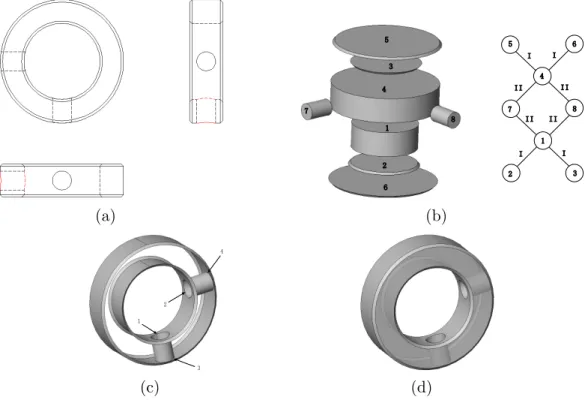
Fig. 8 shows the result of reconstructing a baffle-ring that involves two through holes between the curved surfaces. Fig. 8(a) is the input drawing with 4 poly-line links. Fig. 8(b) shows the recognized primitive QSFs and the graph of their aggregation relations, which were revealed by the hint-based feature recogni-tion proposed in this paper. Fig. 8(c) shows the generated hybrid wire-frame. The space quartic curves that arose from the intersections of cylinder–cylinder are marked with the numbered arrows. The reconstructed model is presented in Fig. 8(d).
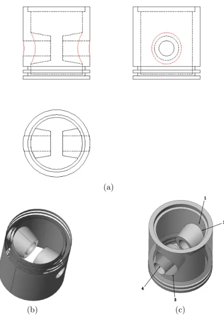
Fig. 9 shows the reconstruction of a piston with two tapers on the curved surface. Based on the input drawing shown in Fig. 9(a), eleven primitive QSFs were recognized, including 2 cones and 9 cylinders. Four non-planar quartic curves are involved in the generated hybrid wire-frame shown in Fig. 9(b), which resulted from the intersections of cylinder–cylinder and cylinder–cone. Fig. 9(c) shows the reconstructed object.
cylin-(a) (b)
(c) (d)
Fig. 8. Baffle-ring: (a) three orthographic views, (b) recognized primitive QSFs (left) and their aggregation relations (right), (c) hybrid wire-frame, (d) reconstructed model.
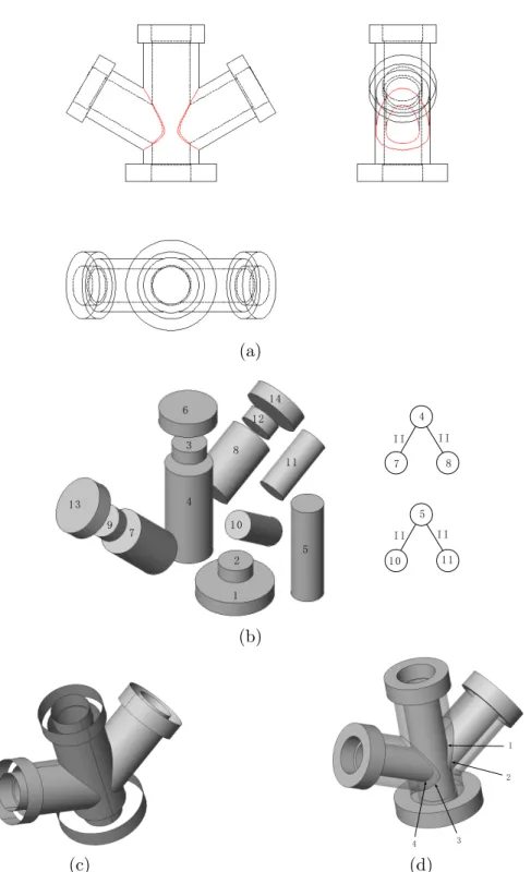
drical surfaces whose axes are not parallel to any of the three coordinate axes. Fig. 10(a) is the input drawing with 6 poly-line links. In Fig. 10(b), 14 primi-tive QSFs were recognized, including 8 cylinders of type 2 as defined in Table 1; the aggregation relations of type II (i.e., spatial intersecting) between the cylinders were also revealed. Consequently, the intersections of the cylinders resulted in 4 space quartic curves, which are involved in the generated hybrid wire-frame shown in Fig. 10(c). The B-rep model was reconstructed as shown in Fig. 10(d).
Due to the non-planar fourth-degree intersections of the quadric surfaces, all the above three examples cannot be handled by the reconstruction methods that employ wire-frames as the intermediate model. Since existing algorithms of generating wire-frames from orthographic views (e.g. [23–26]) only focus on conic edges, higher order curves can not be generated in the wire-frame. While the proposed method can reconstruct objects with higher order curves that result from interacting quadric surfaces with intersecting axes, therefore it covers a broader object domain to be reconstructed than other existing algorithms.
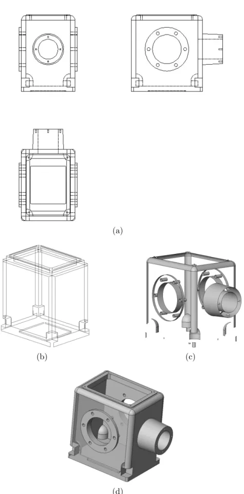
A cuboid hull is provided in Fig. 11 to illustrate the efficiency of our method. This part possesses the complex topology of quadric surfaces that arise from several blends. First, the incomplete wire-frame was generated as shown in Fig. 11(b). Then, 58 primitive QSFs, including 8 spherical surfaces and 1
(a)
(b) (c)
Fig. 9. Piston: (a) three orthographic views, (b) hybrid wire-frame, (c) reconstructed B-rep model.
conical surface, were recognized from the three-view drawing shown in Fig. 11(a). The hybrid wire-frame, shown in Fig. 11(c), was constructed after all the recognized quadric surfaces were sewn into the incomplete wire-frame. Finally, the B-rep model was reconstructed by tracing all the planar surfaces in the hybrid wire-frame. The reconstructed object is shown in Fig. 11(d). The processing time was 406 milliseconds.
The complexity of solid reconstruction depends on the quantity of entities in input drawings, the geometrical coverage of surfaces, and the topological structure of objects. For the B-rep approach, the efficiency is mainly influenced by the construction of curved surfaces. In the existing B-rep algorithms, it is computationally expensive to trace all the valid quadric surfaces due to the search with backtracking and heuristics. A curved surface equation derived
(a)
(b)
(c) (d)
Fig. 10. Four-way pipe: (a) three orthographic views, (b) recognized primitive QSFs (left) and their aggregation relations (right), (c) hybrid wire-frame, (d) recon-structed model.
from the type of two adjacent edges is ill defined since it does not provide strict restriction on the scope of models that can be handled [29]. For exam-ple, a straight edge and a circular edge could define a planar, cylindrical, or conical surface. On the other hand, a quadric surface could be defined by any
(a)
(b) (c)
(d)
two kinds of conic edges. Therefore, the combinatorial search in an exhaustive mode must be employed to retrieve the face topology. Kuo’s method [29] traces quadric face loops that have no inner edges based on the convex hull vertices. However, it is a complex and time-consuming process to check every pair of edges adjacent to every vertex in the wire-frame. Liu et al.[30] employed an ac-celerating technique to trace edge loops based on the correspondence between the 3D loop in the wire-frame and the 2D loop in orthographic views. The method combines 3D edges generated from the 2D links that share a common 2D vertex in every 2D loop. Consequently, its computational complexity is calculated by nl× ˜l× ˜c, where nl is the number of 2D loops in the views, ˜l is
the average number of 2D links in a loop, and ˜c is the average number of 3D edges generated from a 2D link.
While in our algorithm of recognizing QSFs, once an underside-hint in certain view is selected as the initial form of a primitive QSF, the choice of silhouette-and/or intersection-hints in other two views is restricted by the match projec-tions according to the coordinate correspondences. Therefore, the computa-tional complexity of completing the primitive QSF depends on the number of nodes in a circuit, and the number of arcs incident with each node that satisfy the relations for the special hints. Since all the conic nodes in the LRGs are selected as the underside-hints for constructing all the primitive QSFs, the time complexity is nc× ˜m × ˜d, where nc is the number of conic nodes, ˜m is
the average number of nodes in a circuit, and ˜d is the average number of arcs
incident with each node that satisfy the relations for the special hints. Gen-erally nc ¿ nl, since loops are combinations of links in a view. Furthermore,
˜
d ¿ ˜c, because multiple 3D edges are projected onto one link with respect to
the canonical orientation that is a common practice in engineering drawing to orient the object such that it yields the simplest orthographic views. Therefore
nc × ˜m × ˜d ¿ nl× ˜l× ˜c, that is to say, the processing time by our method
can be drastically reduced due to the procedure simplification without the combinatorial search.
7 Conclusion
In this paper, a B-rep oriented algorithm employing a hybrid wire-frame is proposed to construct a 3D curved object from its 2D orthographic views. In view of practicality, the mechanical parts to be reconstructed are limited to two-manifold objects bounded by planar, cylindrical, conic, and spherical surfaces. By our method, all the quadric surfaces are recognized directly from three orthographic views by hint-based pattern matching, and the geometry and topology of curved surfaces are recovered simultaneously. The developed program of the proposed algorithm is reported, in which the incomplete wire-frame, the hybrid wire-wire-frame, and the B-rep model are orderly constructed.
The main advantages of the proposed method are as follows.
• By feature completing based on the hints, the proposed method can
recon-struct objects with space quartic curves that arise from the intersections of quadric surfaces. Therefore, it covers a broader object domain to be recon-structed than other existing algorithms.
• The proposed method retrieves quadric surfaces along with their bounding
edges in a single process. Thus, the processing time can be drastically re-duced due to the procedure simplification without the combinatorial search and backtracking used by the existing algorithms.
The proposed algorithm is limited to perfect input drawings. However, an en-gineering drawing is a mixture of geometry and annotation representations, and sometimes it is difficult to ensure that the drawing is accurate and consis-tent. Therefore, techniques for reconstructing 3D objects from real drawings are necessary to take imperfections into account.
Acknowledgments
The authors thank Prof. Shi-Min Hu for constructive criticisms. The authors also thank Dr. Mark D. Showronski for careful proofreading. Thanks are due to the anonymous reviewers for many helpful comments. This work was sup-ported by the 973 Program of China (Grant No. 2004CB719404) and the Program for New Century Excellent Talents in University (Grant No. NCET-04-0088).
References
[1] Kargas A, Cooley P, Richards THE. Interpretation of engineering drawings as solid models. Computer-Aided Engineering Journal 1988;5(2):67–78.
[2] Nagendra IV, Gujar UG. 3-D objects from 2-D orthographic views – a survey. Computers and Graphics 1988;12(1):111–4.
[3] Wang W, Grinstein GG. A survey of 3D solid reconstruction from 2D projection line drawings. Computer Graphics Forum 1993;12(2):137–58.
[4] Aldefeld B. On automatic recognition of 3D structures from 2D representations. Computer-Aided Design 1983;15(2):59–64.
[5] Aldefeld B, Richter H. Semiautomatic three-dimensional interpretation of line drawing. Computers and Graphics 1984;8(4):371–80.
[6] Chen Z, Perng DB. Automatic reconstruction of 3D solid objects from 2D orthographic views. Pattern Recognition 1988; 21(5):439–49.
[7] Shum SSP, Lau WS, Yuen MMF, Yu KM. Solid reconstruction from orthographic opaque views using incremental extrusion. Computers and Graphics 1997;21(6):787–800.
[8] Shum SSP, Lau WS, Yuen MMF, Yu KM. Solid reconstruction from orthographic views using 2-stage extrusion. Computer-Aided Design 2001; 33(1):91–102.
[9] Soni S, Gurumoorthy B. Handling solids of revolution in volume-based construction of solid models from orthographic views. Journal of Computing and Information Science in Engineering 2003;3:250–9.
[10] Lee H, Han S. Reconstruction of 3D interacting solids of revolution from 2D orthographic views. Computer-Aided Design 2005;37(13):1388–98.
[11] Dimri J, Gurumoorthy B. Handling sectional views in volume-based approach to automatically construct 3D solid from 2D views. Computer-Aided design 2005;37(5):484–95.
[12] Idesawa M. A system to generate a solid figure from three view. Bulletin of the JSME. 1973;16(92):216–25.
[13] Markowsky G, Wesley MA. Fleshing out wire frames. IBM Journal of Research and Development 1980;24(5):582–97.
[14] Wesley MA, Markowsky G. Fleshing out projections. IBM Journal of Research and Development 1981;25(6):934–53.
[15] Preiss K. Algorithms for automatic conversion of a 3-view drawing of a plane-faced part to the 3-D representation. Computers in Industry 1981;2(2):133–9. [16] Gujar UG, Nagendra IV. Construction of 3D solid objects from orthographic
views. Computers and Graphics 1989;13(4):505–21.
[17] Yan QW, Chen CLP, Tang ZS. Efficient algorithm for the reconstruction of 3D objects from orthographic projections. Computer-Aided Design 1994;26(9):699– 717.
[18] Sakurai H, Gossard DC. Solid model input through orthographic views. ACM/SIGGRAPH Computer Graphics 1983;17(3):243–52.
[19] Preiss K. Constructing the solid representation from engineering projections. Computers and Graphics 1984;8(4):381–9.
[20] Lequette R. Automatic construction of curvilinear solids from wireframe views. Computer-Aided Design 1988;20(4):171–80.
[21] You CF, Yang SS. Reconstruction of curvilinear manifold objects from orthographic views. Computers and Graphics 1996;20(2):275–93.
[22] Shin BS, Shin YG. Fast 3D solid model reconstruction from orthographic views. Computer-Aided Design 1998;30(1):63–76.
[23] Kuo MH. Reconstruction of quadric surface solids from three-view engineering drawings. Computer-Aided Design 1998;30(7):517–27.
[24] Zhang AJ, Xue Y et al. Reconstruction of 3D curvilinear wire-frame model from 2D orthographic views. Computational Science - ICCS 2004: 4th International Conference;LNCS 3037:404–11.
[25] Liu SX, Hu SM, Chen YJ, Sun JG. Reconstruction of curved solids from engineering drawings. Computer-Aided Design 2001;33(14):1059–72.
[26] Gong JH, Zhang GF, Zhang H, Sun JG. Reconstruction of 3D curvilinear wire-frame from three orthographic views. Computers and Graphics 2006;30(2):213– 24.
[27] Gu KN, Tang ZS, Sun JG. Reconstruction of 3D objects from orthographic projections. Computer Graphics Forum 1986;5(4):317–23.
[28] Bagali S, Waggenspack WN. A shortest path approach to wire-frame to solid model conversion. ACM symposium on Solid Modeling and Applications 1995;339–50.
[29] Kuo MH. Automatic extraction of quadric surfaces from wire-frame models. Computers and Graphics 2001;25(1):109–19.
[30] Liu SX, Hu SM, Sun JG. Two accelerating techniques for 3D reconstruction. Journal of Computer Science and Technology 2002;17(3):362–8.
[31] Trabelsi A, Carrard M. Feature recognition from 2D and 3D modellers. CompEuro’93 proceedings on Computers in Design, Manufactreing, and Production 1993;210–6.
[32] Miller JR. Geometric approaches to nonplanar quadric surface intersection curves. ACM Transactions on Graphics 1987;6(4):274–307.
[33] Miller JR, Goldman RN. Geometric algorithms for detecting and calculating all conic sections in the intersection of any two natural quadric surfaces. Graphical Models and Image Processing 1995;57(1):55–66.
[34] Vandenbrande JH, Requicha AAG. Spatial reasoning for the automatic recognition of machinable features in solid models. IEEE Transactions on Pattern and Machine Intelligence 1993;15(12):1269–85.