An approach to explore the eddy currents of the new
type divertor for EAST device using ANSYS code
The MIT Faculty has made this article openly available.
Please share
how this access benefits you. Your story matters.
Citation
Liu, ChangLe et al. “An Approach to Explore the Eddy Currents of
the New Type Divertor for EAST Device Using ANSYS Code.” Science
China Technological Sciences 57.1 (2014): 9–13.
As Published
http://dx.doi.org/10.1007/s11431-013-5429-5
Publisher
Springer Berlin Heidelberg
Version
Author's final manuscript
Citable link
http://hdl.handle.net/1721.1/106137
Terms of Use
Article is made available in accordance with the publisher's
policy and may be subject to US copyright law. Please refer to the
publisher's site for terms of use.
Technological Sciences
© Science China Press and Springer-Verlag Berlin Heidelberg 2013 tech.scichina.com link.springer.com
*Corresponding author (email: [email protected])
Special Topic: Nuclear Science and Technology January 2014 Vol.57 No.1: 9–13
• Article • doi: 10.1007/s11431-013-5429-5
An approach to explore the eddy currents of the new type divertor
for EAST device using ANSYS code
LIU ChangLe
1*, YAO DaMao
1, DOODY Jeffrey, LIPSCHULTZ Bruce
2, ZHOU LiHua
2,
LIANG Chao
1, ZHOU ZiBo
1, CAO Lei
1& XU TieJun
11
Institute of Plasma Physics, Chinese Academy of Sciences, Hefei 230031, China;
2 Plasma Science and Fusion Center, Massachusetts Institute of Technology, 190 Albany Street, Cambridge, MA 02139, USA
Received June 26, 2013; accepted November 15, 2013; published online December 13, 2013
An effective method for eddy current calculation has been developed for EAST’s new divertor by using ANSYS. A 3D model of a double null divertor for the EAST device was built to evaluate eddy currents and electromagnetic (EM) forces on these components. The main input to the model is the plasma current and poloidal field coil currents, which are loaded into the mod-el using experimental data measured from the EAST discharges. These currents generate magnetic fimod-elds that match those pro-ducing an EAST discharge, and the time variation of these fields produces the eddy currents in the divertors, along with from the resulting EM forces. In addition, the first 10 time steps were discussed for the eddy current generation and changing trend. It indicates that a static analysis before a transient mode start can solve the eddy current origination in the initial time steps. With this method, the EM transient response of EAST’s new divertor can be predicted based on ANSYS simulations. Fur-thermore, the method is also an effective approach to estimate the EM results for the in-vessel components of a fusion reactor during a disruption.
eddy current, divertor, plasma disruption, EAST (Experimental Advanced Superconducting Tokamak) device, ANSYS
Citation: Liu C L, Yao D M, Doody J, et al. An approach to explore the eddy currents of the new type divertor for EAST device using ANSYS code. Sci
Chi-na Tech Sci, 2014, 57: 913, doi: 10.1007/s11431-013-5429-5
1 Introduction
Experimental Advanced Superconducting Tokamak (EAST) would achieve long pulse operations over 1000 s at plasma current Ip~1 MA and toroidal field BT ~3.5 T with ITER-like
dominant Radio Frequency (RF) heating schemes [1, 2]. It has recently undertaken an extensive upgrade during the shutdown to adopt an ITER-like divertor and other in-vessel components [3, 4]. However, the eddy currents induced in the divertor components by changing plasma currents are concerned, especially in the event of plasma disruption. Therefore, to investigate the electromagnetic (EM) forces in
the divertor components, the eddy currents must be ex-plored in detail before an engineering design, because it is related to the structure safety due to the material property issues [5–7].
To estimate eddy currents, the calculation methods are diverse. Some examples are taken including the classical method by using the EM theory, the simulation based on ANSYS with the preprocessing results from the DINA code, the calculation using the TYPHOON code with magnetic field, etc. [8–11].
In this paper, a method using the ANSYS code to define the eddy current results of the EAST divertor was intro-duced. All the plasma and coil current data were loaded via the ANSYS load step, extension Si (i, the time step) files, with data coming from the EAST discharge experiments.
10 Liu C L, et al. Sci China Tech Sci January (2014) Vol.57 No.1 The key technical issues were focused on the description of
the plasma currents and the coil currents. To demonstrate the simulation, a finite element model of 4.5° sector would be used to address the detailed process in the eddy current simulations.
2 Eddy current issues of EAST new divertor
2.1 Upgrade design on EAST divertor
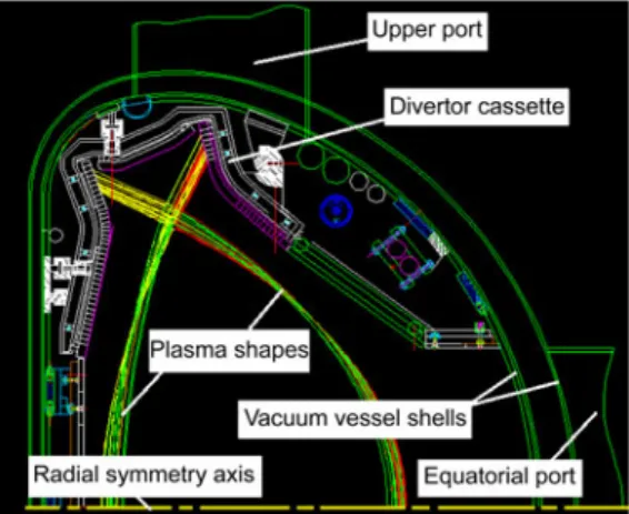
The EAST new divertor will match the operations in dif-ferent phases [12]. In the previous design, the EAST di-vertor just used a separated structure with the cooling sys-tem [13]. According to the new physics targets in the next steps, EAST needs to enhance the core parameters, which leads to a higher heat flux on the divertor components. No-tably, it was reported that the ITER divertor had the re-quirement not only of heat removal capability, but also to provide sufficient mechanical strength to withstand the EM loads [14]. In view of this, a cassette structure similar to the ITER divertor should be adopted for EAST to meet the higher heat flux target in this phase, as shown in Figure 1. However, since the EM loads of the EAST divertor are dif-ferent from ITER, the EM loads on the new EAST divertor design need to be defined and investigated.
2.2 Eddy currents in the divertor components
Since the EM load parameters are the input data for the mechanics analysis, the EM transient analysis is ongoing now in line with the design activities of the EAST divertor. In particular, the main focus is the induced EM forces on the divertor components due to the eddy currents.
For the EAST device, the divertor components will be influenced by the fields generated by the plasma currents and the outer coils due to the induced current effects. The effects of the induced eddy current are up to the fast current changing of the relative coils [15]. For in-vessel compo-
Figure 1 Half cross section of EAST vacuum vessel.
nents of fusion device, it was reported that the large eddy current would be induced on the heat sink with high con-ductivity during the disruption of plasma [16]. Therefore, the eddy currents in the divertor are mainly a concern dur-ing the disruption of the core plasma. In addition, in view of the changing of the currents in the superconductor coils, the PF (poloidal field) and TF (toroidal field) coils should be included. However, comparing to the currents in the PF coils, the currents in the TF coils almost keep constant, thus, the concern can be focused on the currents in the PF coils. In the EAST device, the currents exist in the superconductor coils provided by the outer powers from the discharges start to the end. The significant changes in the currents of the PF coils can be measured with 14 sets of data during one dis-charge shot. In the same case, the plasma currents can also be measured along with a shot time by using Rogowski coils. The plasma and coil current data are applied to the input data of the EM analysis in the simulations.
3 Eddy current calculation
To explore the eddy currents in the new divertor compo-nents, a 3D finite element (FE) model was established. It included the double-null divertors, 14 PF coils, the plasma filaments, and the vacuum zones, as shown in Figure 2. The element for the EM calculations was chosen as solid 97, which has AX, AY, AZ degrees of freedom.
3.1 Plasma current discretization
It was reported that the plasma current can be considered as a rigid current ring, and the plasma current can be shown as an exponential function [17]:
I = I0 exp(t /τ),
where I0 =1.0 MA, t, time (s), = 3 ms. Thus, an equivalent
method for plasma currents was taken into account using a linear or a thin rectangular solid body. Namely, the plasma currents are represented by a number of currents carrying filaments, and they are located in the center of the core
plasma area. The currents of the plasma filaments vary rap-idly in the plasma disruption. According to the core domain area, the filament number can be chosen as 24, and the cur-rents in these filaments are calculated to generate the same field as the plasma during a shot [18]. The current in each filament varies with time throughout the discharge, and as a result, there is a data file of time varying currents for the filaments. It can be applied to the filament bodies by the ANSYS commands.
3.2 Load files
Using the ANSYS code for eddy current simulation, the key step is the load files, which load the input data of the plasma filament currents and the PF coil currents. These files define the current parameters at each time step. Each step has only one set of the measured data of currents for all plasma fila-ments and the PF coils in the discharge. In this study, the discharge was broken up into 79 time steps.
In addition, one load file was combined with the current information by algorithmic processor description language (APDL) of the ANSYS code. It is called the Si (i=1–79) files. Finally, all the Si files were edited into one folder with the same dictionary path, which can be read and loaded in the ANSYS code successively while the simulation was run. 3.3 Boundary conditions
In the 3D FE model, a key point of the zero voltage was set in one corner of the model, which served for the high volt-age discharge. Otherwise, there was overflow on the high voltage in the model. A “D” shape domain was set as the air zone, enclosing the divertors and the PF coils. A 4.5° sec-tor of the vessel and diversec-tor were modeled using cyclic symmetry, so symmetry boundary conditions need to be set on the two side surfaces of the “D” shape model. Figure 3 shows the boundary conditions applied to the model.
In addition, the FE model coordinate system should be
changed to cylinder system if there was an original Carte-
Figure 3 Boundary conditions.
sian system of the three-dimensional model. The mesh ele-ments must be rotated into the cylindrical system for current and field calculations.
3.4 Calculation and discussion
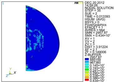
The calculation results include the induced field, the in-duced current density, the EM force from the inin-duced cur-rents, etc. Since there were 79 time steps, the EM results will have 79 steps along the time variation. For example, Figure 4 just displays the induced magnetic field at time of 0.013393, and Figure 5 only shows the EM force distribu-tion at time of 0.13776, the maximum value of the induced EM forces is located in the inner target area.
In fact, there are 79 steps of the induced fields which show the magnetic fields changing during the shot time, just the same as the eddy currents and their induced EM forces. In this case, there are 79 eddy current results and the corre-sponding induced EM forces for each step, which can be
Figure 4 Induced EM field at time of 0.013393.
12 Liu C L, et al. Sci China Tech Sci January (2014) Vol.57 No.1 described as result-time step figures. The plots indicate that
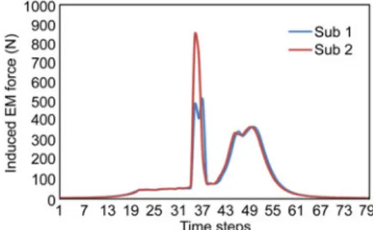
the induced currents and the EM forces change with the time. Figure 6 shows the change for the induced current density with two kinds of sub-time step.
It is noteworthy that the maximum value of the eddy current density is 362 MA m2 at sub time step of two. It was located in the beginning of the plasma current changing where the values drop down rapidly along the first several time steps. However, we expect the eddy currents to be zero at the beginning time and then be induced from zero to a relatively high value due to the plasma current decay. The large current at the beginning is an artifact of the analysis processing. The problem is because of the choice of analysis type in the analysis processing. Therefore, the results of the first 10 steps should be abandoned since they do not reflect the real cases of the time steps. To eliminate this problem, the transient analysis must begin with the plasma at a steady state operation, instead of starting with no plasma current as has been done. Therefore, the results of the first 10 steps could be ignored since it could not reflect the real case of operation. To solve the problem, a static analysis was per-formed inside the first 10 time steps and used as an initial condition. The updated results are shown in Figure 7.
However, the second peak current density is in the time steps range of 35–36 and 41–56. These peaks covered the real cases of the induced currents with the time steps, the
maximum value was 124 MA m2. The effective values
ranged from 6.46 to 67.1 MA m2. They could be consid-ered as the eddy current density induced by the changing currents of the plasma filaments and the PF coils, as shown
Figure 6 Induced current density with time steps.
Figure 7 New results after adding a static analysis.
in Figures 5 and 6. Correspondingly, the peak EM force was 841.622 N at step of 35, and the effective EM force ranged from 86.74 to 368.88 N, as shown in Figure 8. Thus, the induced currents in the divertor components followed a trend from zero value to a peak value over the time of the disruption.
In addition to the measured data of the PF coil currents, the experimental data of the plasma currents also reflected the fast changing with the time steps from the initial change of the plasma to end in the disruption. Since the plasma currents can be discretized with the time steps based on the above exponential function, for the vessel components of other fusion devices, even for future reactors, their EM transient behavior could be predicted on the EM results once the current functions were obtained. The measured data in this study was really a set of discretized data from experimental discharges.
On the other hand, owing to the induced currents coming from the induced magnetic fields, once the changing fields of outer coils are obtained by some codes of magnetic anal-ysis, like the PF coils, the EM calculations can also be pre-dicted based on the magnetic field discretization.
4 Summary
A method using 1D current filaments to recreate the fields generated by the plasma in the EAST tokamak is an effec-tive way to simulate the rapid changing of magnetic fields due to changes in the plasma current during a disruption. The Si load files (i=time step) used by APDL language can combine the filament current data along with data for the coil currents as the input data for the ANSYS code. This is the key step for the ANSYS calculations. This indicates that the ANSYS FE method can simulate the transient changing of the plasma currents and the coil currents and predict the magnetic fields, eddy currents and the relative EM forces with a set of continuous results.
In addition, it indicates that the measured current data from EAST discharge can be used to simulate the plasma disruption according to the time steps. However, the func-tion of the current data could also be applied and loaded in the code for calculation as long as it can be discretized with
the time. Therefore, it is an effective approach to the EM analysis which can be not only applied for EAST divertor components with the measured data, but also can be served for the in-vessel components analysis of a future fusion re-actor, as long as the current data can be described with a classic function or the discretized magnetic fields.
This work was supported by the National Basic Research Program of Chi-na (“973” Program) (Grant No. 2013GB10200).
1 Wan Y X. Overview of steady state operation of HT-7 and present status of the HT-7U project. Nucl Fusion, 2000, 40(6): 1057– 1068 2 Wan B N. Recent experiments in the EAST and HT-7
superconduct-ing tokamaks, Nucl Fusion, 2009, 49 (10): 104011
3 Guo H Y, Gao X, Li J, et al. Recent progress on divertor operations in EAST. J Nucl Mater, 2011, 415(1): 369–374
4 Guo H Y, Chen Y P, Liu S C, et al. Effect of magnetic geometry on divertor asymmetry and access to high confinement mode in EAST. J Nucl Mater, 2013, http://dx.doi.org/10.1016/j.jnucmat.2013.01.047 5 Chen L, Wen W D, Cui H T. Generalization of Hill’s yield criterion
to tension-compression asymmetry materials. Sci China Tech Sci, 2013, 56: 89–97
6 Liu W T, Zhang Y, Feng Z J, et al. Effects of stick-slip on stress intensity factors for subsurface short cracks in rolling contact. Sci China Tech Sci, 2013, 56: 2413–2421 7 Deng S, Han X H, Qin X P, et al. Subsurface crack propagation under
rolling contact fatigue in bearing ring. Sci China Tech Sci, 2013, 56: 2422–2432
8 Giesen B, Neubauer O, Bondarchuk E, et al. Panin. Investigation of
eddy currents in the components of the dynamic ergodic divertor of TEXTOR using analytical and numerical approaches. Fusion Eng Des, 2003, 66-68: 419– 423
9 Bandyopadhyay I, Deshpande S P, Chaturvedi S, et al. Design analy-sis of plasma position control in SST1. Fusion Eng Des, 2001, 54(2): 151–166
10 Jhang H, Kessel C, Pomphrey N, et al. Design calculations for fast plasma position control in Korea Superconducting Tokamak Ad-vanced Research. Fusion Eng Des, 1999, 45(1): 101–115
11 Alekseev A, Arslanova D, Belovet A, et al. Computational models for electromagnetic transients in ITER vacuum vessel, cryostat and thermal shield. Fusion Eng Des, http://dx.doi.org/10.1016/j.fusengdes. 2013.01.102
12 Yao D M, Li J G, Song Y T, et al. EAST in-vessel components de-sign. Fusion Eng Des, 2005,75–79 : 491–494
13 Song Y T, Peng X B, Xie H, et al. Plasma facing components of EAST. Fusion Eng Des, 2010, 85(10-12): 2323–2327
14 Janeschitz G, Tivey R, Antipenkov A, et al. Overview of the divertor design and its integration into RTO: RC-ITER. Fusion Eng Des, 2000, 49–50: 107–117
15 Zhu Y F, Liu C L, Liu, X F, et al. Design and analysis of the thermal shield of the prototype superconducting dipole magnet for GSI. IEEE T Appl Supercond, 2013, 23(2): 4001108
16 Liu X F, Du S J, Yao D M, et al. The design, analysis and alignment of EAST divertor. Fusion Eng Des, 2009, 84(1): 78–82
17 Du S J, Wang L H, Liu X F, et al. Electromagnetic analysis of the passive stabilizers for EAST. Fusion Eng Des, 2006, 81(19): 2267– 2273
18 Doody J, Granets, Lipschultz B, et al. ANSYS model to predict magnetic fields and loads in Alcator C-Mod’s new outer divertor during a disruption. ANS 20th Topical Meeting on the Technology of Fusion Energy (TOFE 2012), Nashville, USA, 2012