HAL Id: in2p3-00667477
http://hal.in2p3.fr/in2p3-00667477
Submitted on 7 Feb 2012
HAL is a multi-disciplinary open access
archive for the deposit and dissemination of
sci-entific research documents, whether they are
pub-lished or not. The documents may come from
teaching and research institutions in France or
abroad, or from public or private research centers.
L’archive ouverte pluridisciplinaire HAL, est
destinée au dépôt et à la diffusion de documents
scientifiques de niveau recherche, publiés ou non,
émanant des établissements d’enseignement et de
recherche français ou étrangers, des laboratoires
publics ou privés.
Controlling the GANIL from an Operatoor Workstation
L. David, E. Lécorché, C. Maugeais, M. Ulrich
To cite this version:
L. David, E. Lécorché, C. Maugeais, M. Ulrich. Controlling the GANIL from an Operatoor
Work-station. EPAC 94 - Fourth European Particle Accelerator Conference, Jun 1994, London, United
Kingdom. pp.1800-1802, 1994. �in2p3-00667477�
Controlling
the GANIL from an Operator Workstation
L. David, E. UcorchC, C. Maugeais,
M. Ulrich.
GANIL -B.P. 5027
F - 14021 Caen Cedex
Absfracf
A new control system is in use at GANLL since February 93. The aim of this evolution was to replace the precedent sequential way of control by a simultaneous mode so that a larger number of pieces of equipment can be handle at the same time. Afterwards, it could provide enough facilities to reduce the ion beam starting time.
We describe how all component parts of the accelerator are controlled from the main control room. It emphasises the distribution of intelligence, using a client-server model between the X-Windows based man-machine interface and the Camac real-time processors with RTVAX chips. The Ethernet network architecture and some tuning beam programs and control functions are also discussed.
Lastly, advantages expected from this new control system, specially for integration of new projects such as high intensity transport and secondary beams are presented,
INTRODUCTION
The whole GANIL control system had been upgraded from 1989 to February 1993 so allowing the GANIL facility to be operated by this new control system since that time. This upgrade was mainly implied by the need of more powerful tools in order to reduce the beam tuning time or to integrate new devices or future extensions. Also, the former control system designed more than 10 years ago was becoming obsolete in size and capabilities.
Due to the existing system, many constraints had to be considered when upgrading : the old computers did not have any capability to be linked to any network, the front-end installation consisting of more than 30 CAMAC crates should be kept for economical reasons, the software was not portable and the entire application had to be rewritten. Lastly this upgrade has to be been performed without disturbing the operation of the machine and no specific shutdown time could be devoted to it.
1. THE GANIL CONTROL SYSTEM
The new control system has already been described elsewhere [I,21 and it spreads over two layers consisting of the development and real time layers.
The basic options for this system are :
- Communications between the processors are achieved through an Erherner network, networking protocols being DECner, TCP-IP or OSi,
- VAXfVMS cornpuiers are used either for development purposes or to be a setver machine at the real time level, - VAXYVMS ~orkstuiions are the man-machine interface devices, under the MofifX-win&~ environment,
- Kinetics 3968 Vantage 300 modules including the RTVAX processors are used to control each of the C.4MAC crates. These Vnnmge 300 modules run the VAXELN real-time
operating system and allow an easy integration among the VAX environment,
- VME crates are driven by the AEON VME300 boards also based on the snme RTVAX processor and running VA.XELN too,
- PLCs integrated in the control system are the APRIL PI3400 or SIEMENS 135 U cotmollers seen from the system through the IMAGIN piece of software,
- Because of its high security level and the software development capabilities it implies, ADA has been chosen as the main programming language,
- The INGRES relational database management system provides most of the dam management [31.
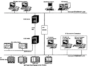
The general configuration of figure 1 shows that all the system lies on the client/server model. The front end crates run the pieces of equipment handlers and receive from the central database extraction so that each crate is entirely autonomous aftetwards. The VAX 4400
is the central server
for the real time level and run general purpose processes such as the front end database server or the alarm server displaying alarms on an X-window terminal and logging alarms in a specific database.
Figure 1 : The general control system layout
2. THEHUMAN MACHINEINTERFACE
The operator console consists of set of a VS4000 workstation and a VXT 2000 graphic X terminal, with a shaft device called dial-box with S ‘knobs.
2.1 Individual corflm7nds.
The X terminal allows individual access to every piece of equipment. The screen is divided in two windows. each of them dedicated to a specific process on the workstation. - The first process called CHOICE displays, from the database, menus consisting of all the accelerator control modules. This 1800
list is made with several pull down menus. The first one lists the different kinds of pieces of equipment (quadrupoles, beam profilers, motors...). The next one is dedicated to the localisation (ECR sources, injectors, cyclotrons, beam lines . ..). The last menu is in fact a scrolled list box with the name of the pieces of equipment.
- The second window is managed by the HOOK process and is divided into 8 small identical windows, each of them is associated with a knob on the dial-box, so 8 pieces of equipment can be reached simultaneously. A push button allows the operator to confirm the selection performed through the CHOICE process. Controlling a piece of equipment is done through an On/Off button, the setting value is introduced by the keyboard or modified using the associated knob on the dial-box. A label widget shows the current value which is returned by the front-end crates on significant changes. The piece of equipment status is displayed on a specific widget and a push button can be used to obtain more details about the status.
Figure 2 : A piece of equipment window
2.2 Tuning applications
Beside of these individual commands Ada programs have been written to achieve fully customized controls of many types of components in a global mode.
2.2.1 Beam handling
The main program is GEST-PARAM, detailed in paragraph 3. .4 second one BROWNU determines the NMR frequency to apply to a magnet to get the right energy for a specific ion. Inversely, it calculates the energy and Bp for a NM R frequency measured in a magnet.
2.2.2 Beurn tuning
INJECTION CENTERING : A first progmm displays the 1OsSeS on the diagnostics located in the injection and ejection areas of the main cyclotrons. An other program measures the losses in the injection diagnostics and reacts on the steerers of the transport beam line for optimization.
TRIMhdING THE CYCLOTRON MAGNETS : After cycling the m,ain coil, the program measures the magnetic field in each of
the four sectors and adjust the ancill‘ary coils to equilibrate them.
ISOCHRONISM : This program measures the main phase Of
the ion packets and adjusts the magnetic field so that the ions turn in the same time, whatever is the radius.
STRIPPER : This program handles the stripper, driving the interlock devices when inserting a new foil. It also stores information in the database such as the foil characteristics, their lifetime, for statistic purpose,
SOURCE ANALYSIS : This program analyses by mass
spectrometry the different ion charges which are produced. 2.2.3 Remote control
Some RTVAX based CAMAC or WvlE crates have to control a whole electronic system in a local way. They interface with some specific applications run on the workstations :
BEAM SWITCHING : This application has to switch the beam
between two experimental rooms by controlling pulsed power supplies. It gets the Switching time and power supplies settings and displays the status of the whole experimental area.
PHASE LOCK OF THE BUNCHER AND RF CONTROL : A fist application displays and controls automatically the buncher phase to optimize the injection in the frst cyclotron, others drive each of the 7 RF cavities.
BEAM PROFILERS : To replace the beam profiles displayed on oscilloscopes, an application will display in the same way all the kinds of profilers. For the high intensity transport operation, new beam profilers will be added to the multiwire profiles : ionization of residual gas ‘profilers and spiral scanners. The acquisition is done in a VMlZ crate, using house made slots for the multiwire and the spiral scanner and a Jbus link for the ionization gas profilers. Others programs have to be written to optimize the tuning of the beam lines : automatic alignment, transverse emittance measures, automatic adaptation and achromatism controls.
RADIAL PROBES : To display each beam turn in the cyclotrons, a CAMAC controller will perform the control and the acquisitions on the radial probes in a local way and all the results will be sent in one time. This application will replace the existing program run on the workstations. Also for the high intensity transport, a new VME controlled probe will be added in the deflector elements, to <can the last three turns before ejecting.
2.3 Graphical developments
Some programs have been written text-mode oriented, by lack of time. They use the VMS library SMG, with an Ada binding, Now most of the new programs have to be written using the common X-window environment.
The static part of the screens (widgets and menus) is developed with the DEC VUIT graphical editor and UIL files generation. These files are compiled to become UID files which are loaded by the Motif subroutines. Some others widgets are created directly at run time and all of them are animated by Motif subroutines with an Ada binding available in the public domain.
But as the Motif library cannot be used in the same time by several Ada tasks in a single process we had to write a graphic task server for every X-window program and to modify the X main loop inside. As DEC doesn’t support VUIT anymore, we are planning to use the BX editor and for the graphs Y=f(t) we are evaluating the XRT-graph widget instead of DEC GOBE.
3. THE BEAM PARAMETER MANAGEMENT SYSTEM
An important work has been done jointly with the Beam Parameter Group in order to provide the appropriate services needed by the beam parameter management relying on the BDPARAM database and the GEST-PARAM application. 1801
3.1 The BDPARAM database
The BDPARAM is implemented with the INGRES relational database management system as schematically shown on figure 3.
ca1cr
Ma?sn-“*WI QICTeCUS MW4C+~“uU,
‘Nnri lhmY @NW7
_ nacmTu!.mc~rJ WHOJa
-cv*w lwWO~“ALln -
Figure 3 : Overview of the beam parameter database
I
- In a first step the various tunings achievable for the GANIL facility are listed in the GANIL table according to the beam path BEAM-PATH with the corresponding beam optic configurations BEAM-OPTIC. Furthermore the beam path is divided into intrinsic segments named PATH-SEGMENT, each segment constitutes an indivisihle element for the tuning of the machine and can belong to several beam paths. - Then aII the entities associated to the beam parameters i.e. the pieces of equipment, beam characteristics ,.. are described in the ENTITIES table within an object-oriented approach and ‘are sorted along the segment they belong to.
J+eorewnff-lrne a
- A software bridge has been added to the existing Fortran PARAM program calculating the beam parameters. From the output PARAM files, SQL batch procedures then fill the BEAM-DESCRIPTION, THEORETICAL-SETS and THEORETICAL-VALUES tables. Each beam is identified by its BEAM-ID corresponding to the ion to be accelerated, to the ion charges at the injector output and after the stripper, as well as to the beam energy and the RF frequency. For any beam to be accelerated, the entity values for ten b‘asic optic contigurations are stored in the dambase, the association of a beam und an optic configuration is identified by the THEORETICAL-OPTIC-ID index.
Pourmeter nrcm
- Various settings of the machine can be stored in the RUNS, TUNING-SETS and TUNING-VALUES tables. Accelerating a beam specified by its BEAM-ID is an operation run designated by the RIM-ID ident. For each run, severnl sets of values can he archived ; these sets are
identified by the TUNING-ID attribute associated to a bea,m and a run operation.
- Batch procedures allow to recover tunings archived by the first generation control system or to load RMS files generated by GEST-PAEUM.
Beam prepamtion,
- Interactive and batch procedures allow to prepare beams to be accelerated from either theoretical VakS Or tuning values already stored in the database. The beam parameters generated are set into the BEAIKPREPARATION table from which RMS files are extracted to be read by GEST-PARAM.
3.2 The GEST-PARAM application
The GEST-PARAM application which runs on any operation workstation deals with all the on-line beam parameter management.
Figure 4 : The beam parameter flow diagram.
To get the parameter values for the beam to be accelerated, GEST-PARAM reads the RMS files prepared from the database and then set to @e right values all the entities required by the optic configuration. The application also takes care of the injector cyclotron switching, the beam characteristic changes or any new beam occurrence. Parameters archiving can also be performed through this application and generate RMS files optionally loaded in the BDPARAM database. Beside of that for some specific phases GEST-PARAM directly interfaces the BDPARAM database and tables updated by GEST-PARAM can be accessed from any application to get various information concerning the operation currently done.
In order to improve the response times and to provide an entire separation between the off-line parameter management and the on-line constraints, the database BDPARAM is distributed in the development and the control computers with some automatic replication tools to maintain the basic integrity and coherence. We plan to develop a Motif version of the GEST-PARAM application directly accessing the database either for the beam preparation or the parameter archiving.
References
[l] L. David, E. L;corch& T.T. Luong, M. Ulrich. ‘The Next Generation Control System of GANIL’ Proc. Int. Conf. on Accelerator and Large Experimental Physics Control Systems, Tsukuba. 1991
[Z] T.T. Luong et al., ‘The New Accelerator Control System of
GANIL’ Int. Conf. on Accelerator and Large Experimental Physics Control Systems, Berlin 1993
[3] E. LicorchC, P. Lermine, ‘Database Management in the New GANIL Control System’ Int. Conf. on Accelerator and Large Experimental Physics Control Systems, Berlin 1993