HAL Id: in2p3-00260274
http://hal.in2p3.fr/in2p3-00260274
Submitted on 3 Mar 2008HAL is a multi-disciplinary open access archive for the deposit and dissemination of sci-entific research documents, whether they are pub-lished or not. The documents may come from teaching and research institutions in France or abroad, or from public or private research centers.
L’archive ouverte pluridisciplinaire HAL, est destinée au dépôt et à la diffusion de documents scientifiques de niveau recherche, publiés ou non, émanant des établissements d’enseignement et de recherche français ou étrangers, des laboratoires publics ou privés.
To cite this version:
R. Beunard. The alignment strategy for the SPIRAL2 superconducting LINAC cryomodules. 10th International Workshop on Accelerator Alignment - IWAA08, Feb 2008, Tsukuba, Japan. 2008. �in2p3-00260274�
THE ALIGNMENT STRATEGY FOR THE SPIRAL2 SUPERCONDUCTING
LINAC CRYOMODULES
R. Beunard, GANIL, BP 55027, 14076 CAEN, CEDEX 5, France
Abstract
The SPIRAL2* project, located at the GANIL** facility in Caen, France, has been studied since the beginning of 2001, and is now under construction. This project aims at delivering energetic rare (radioactive) isotope beams with intensities not yet available with presently running machines. An important aspect of this project is that it will allow GANIL to deliver to users up to five different beams in parallel.
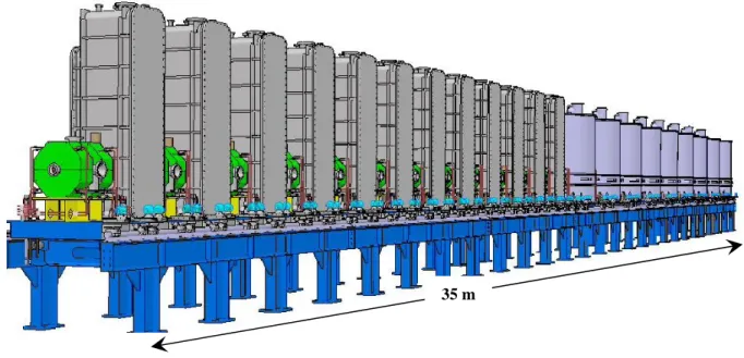
This paper is focused exclusively on the alignment strategy which will be used for the LINAC superconducting cryomodules (Fig. 1). It is composed of two cryomodule families, one of low beta, called Cryomodule A, and one of high beta, called Cryomodule B. According to the beam dynamics calculations, all the cavities will operate at 88 MHz: one family at beta =0.07 and the other at beta = 0.12.
The solution adopted to support the LINAC components is a welded-frame structure equipped with a guide rail. One advantage of this solution is the possibility to bring a component to a laboratory together with its support, for example, in order to do a realignment of the cavities in the cryostat, then to install it back on the beam line under the same conditions, using the guide rails.
During the assembly process, once the cryomodule is closed, the interior of the superconducting cavities cannot be accessed outside a clean room. As a result, the cavity will have to be equipped with optical targets mounted on an arm in order to facilitate its alignment inside the cryostat. For the final phase, special target boxes (fiducials) will be adjusted on the sides of cryomodules supports to ensure their alignment on the guide rails. Alignment will be controlled at each stage of the assembly process [1] [2].
Figure 1 : Layout of the SPIRAL2 superconducting linac cryomodules
____________________________________________
* SPIRAL2 : Système de Production d’Ions Radioactifs Accélérés en Ligne [production system of on-line accelerated radioactive ions] ** GANIL: Grand Accélérateur National d’Ions Lourds [Large-scale national accelerator for heavy ions]
≅20 m
INTRODUCTION
SPIRAL2 is the project of a facility intended for the production of new beams of stable and radioactive ions at GANIL. The SPIRAL2 facility is based on a high-power superconducting driver linac which delivers a high-intensity, 40-MeV deuteron beam, as well as a variety of heavy-ion beams with mass-to-charge ratio equal to 3 and energy up to 14.5 MeV/u. The driver accelerator will send stable beams to a new experimental area and to a cave for the production of radioactive ion beams (RIBs). The commissioning of the driver should start in 2011 at GANIL.
Fast neutrons produced from the break-up of the 5-mA deuteron beam using a carbon converter will induce up to 1014 fissions/s in a uranium carbide target.The extracted RIB will subsequently be accelerated to energies up to 20 MeV/u (typically 6-7 MeV/u for fission fragments) by the existing CIME cyclotron.
This paper is focused mainly on the survey and alignment techniques selected for installation of the SPIRAL2 linac superconducting cryomodules. We will also present the survey instruments which will be used for alignment.
THE LINAC SUPERCONDUCTING
CRYOMODULES
The linac itself is based on superconducting independently-phased resonators. It is composed of 2 families of quarter-wave resonators (QWRs) at 88MHz, developed respectively by the CEA/DAPNIA and the IN2P3/IPNO teams: 12 resonators (Fig. 2) with βo=0.07 (1 cavity/cryomodule) and 16 resonators (Fig. 3) at βo=0.12 (2 cavities/cryomodule). The transverse focusing is ensured by means of warm quadrupole doublets located between each cryomodule. These warm sections include also beam diagnostic boxes and vacuum pumps.
The peculiarity of the cavities is that they made up of niobium. This is one of the materials used for superconducting equip–ment. In the framework of the project, the ‘Cryomodule A’ refers to the first family. Twelve superconducting
cavities of this first kind take over the beam after the RFQ to continue the acceleration. These first cavities are optimised for speeds around 7% of the speed of light. Each cryomodule contains a single cavity. The cavity vacuum and the temperature isolation vacuum are separated. The cryomodule is box-shaped with a removable panel on each side for easy access. The cavity will be supported and
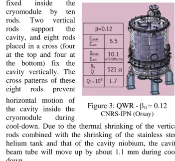
fixed inside the cryomodule by ten rods. Two vertical rods support the cavity, and eight rods placed in a cross (four at the top and four at the bottom) fix the cavity vertically. The cross patterns of these eight rods prevent horizontal motion of the cavity inside the cryomodule during
cool-down. Due to the thermal shrinking of the vertical rods combined with the shrinking of the stainless steel helium tank and that of the cavity niobium, the cavity beam tube will move up by about 1.1 mm during cool-down.
In the framework of the project, the ‘Cryomodule B’ refers to the second family. Eighteen superconducting cavities of this type will be used along the last part of the linac, so that the ions reach higher velocities. These cavities are optimised for 12% of the speed of light. Each cryomodule contains two
cavities. The insulation vacuum and cavity vacuum are separated. The cavity will be supported and kept in position by means of three vertical and four horizontal rods (Fig. 4). The horizontal rods placed in a cross will prevent lateral movements during the cryomodule cooling down. For the vertical position the combined shrinkage of the rods and the cavity helium vessel will induce a
displacement of around 1.5 mm. It is possible to adjust this position from outside the cryostat vacuum vessel once the cryomodule will be cold. Simulated values for the cavity axis displacement during cool-down may have some uncertainties and will be measured on a prototype assembly [3].
The integration aspects
The solution adopted to support the linac components is a welded-frame structure equipped with a guide rail (Fig.8). One advantage of this solution is the possibility to bring a component a laboratory together with its support in order to do, for example, a realignment of the cavities in the cryostat, and then to install it back on the beam line under the same conditions, using the guide rail.
The linac ‘tunnel’ width is intended to be sufficient to install all the components and space is also reserved for activities like the safety and alignment processes. For Figure 2: QWR - β0 = 0.07
CEA/DSM/DAPNIA (Saclay)
Figure 3: QWR - β0 = 0.12
CNRS-IPN (Orsay)
Figure 4: View of three vertical and four
survey, the necessary space on the same side as fiducials of the cryomodules was defined during the integration of drawings in the design office.
Alignment tolerances
The tolerated maximum static errors for the global alignment are:
- ± 0.1 mm for the displacement of the quadrupoles - ± 0.03° for the rotations (X,Y) of the quadrupoles - ± 0.2° for the rotation (Z) of the quadrupoles - ± 1 mm for the displacement of the cryomodules - ± 0.3° for the rotation (X,Y) of the cryomodules - ± 0.25 mm for the displacement of the BPM
Components fiducialization bench
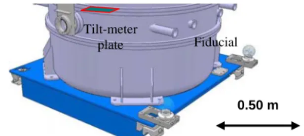
As the components cannot be aligned through the beam tube, the solution adopted is to transfer new axes outside the object (quadrupole and cryomodule), i.e. to the sides of their supports, by adjustable target boxes or fiducials (Fig. 8 and 9). These external references will allow the alignment of one cryomodule cavity with respect to the others. The transverse tilt of cryomodules will be given by a plate fixed to the cryostat.
The shifting of the beam axis will be carried out on a dedicated bench. The design work is presently in progress (Fig. 5). The spatial coordinates of these fiducials would be given in the reference system of the accelerating tubes of the cavities (after alignment inside cryomodule) and the mechanical axis of the poles for the magnets.
Before beginning the fiducialization, the bench rails will be carefully aligned parallel to each other by using a special tool (Fig.6). It will be necessary to pay careful attention to the alignment of these rails, particularly the guide rail, which will become the unique baseline for positioning of fiducialization tools. This bench is a section of the linac welded-frame structure. The principle is to define a line in 3D-space for each shifted axis. To realize these lines, we will fix a machined plate
referenced to the guide rail at each end of the bench. These plates include the different machined holes placed according to the shifted axis, which
can locate respectively a Micro-Alignment Telescopes (MAT) and a Taylor-Hobson reticule (Fig.5).
The three-dimensional coordinate measurements of these fiducials will be done by means of a portable-arm coordinate-measuring machine. The measuring accuracy given by this system is ± 0.06 mm (at 2σ).
To ensure the measurement accuracy by using the portable arm, it is essential to define a plane in the object volume. This plane is defined on the object’s frame by three spherical-head benchmarks previously adjusted in the same plane (Fig. 7).
Transfer methodology of the qualifying
cryomodule A cavity beam axis
Once the cryomodule is closed, it no longer possible to change the cavity position with respect to the vacuum tank. External references of the cavity position will allow the alignment of one cryomodule cavity with respect to
Figure 9: Cryomodule B fiducialization
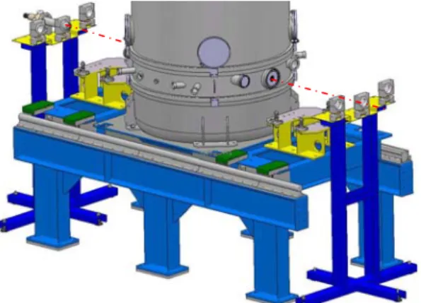
Figure 5: Components fiducialization bench
Figure 8: Cryomodule A and quadrupoles fiducialization
Fiducial 0.50m Guide rail Tilt-meter plate
Figure 7: Benchmarks plane Figure 6: Alignment tool of the rails
Guide rail Telescopes Reticule 0.50 m Fiducial Tilt-meter plate
the others (Fig. 10). Previous measurements of the cavity beam axis displacement during cool-down will be necessary to check the calculation. This will be made using a bare cavity [4].
Transfer methodology of the qualifying
cryomodule B cavities beam axis
During the assembly process, once the cryomodule is closed, the interior of the superconducting cavities cannot be accessed outside a clean room. As a result, the cavity will have to be equipped with external references (optical targets) mounted on an arm in order to facilitate its adjustment inside the cryostat (Fig.11). The rotation of the cavity around the beam axis inside the cryostat will be adjusted by applying the angle measured by means of the tilt-meter during the operation of fiducialization. After a levelling process of the cavity, the transfer is carried out
by means of inter-dependent tools in the two beam tubes. The positioning of the target supports is obtained via to a rod inserted in the arms of the alignment tools (Fig.12). The target supports can be taken apart to permit chemical cleaning operations [5].
Qualifying cryomodule B: measurement of the
cavities motion during vacuum tests and
cooling down
The technical principles include an optical method to control the cavities alignment and the possibility of vertical adjustment of the cavities from the outside once the cryomodule is cooled down (Figs 13 and 14).
Some solutions are being studied to measure the displacements during vacuum tests and cooling down. The best solution for measuring the displacements of the three tubes in all directions is the capacitive technique. For reasons of cost, this solution was not adopted for the
test cryomodules [6]. Consequently, on this cryomodule, an optical measurement through on windows will be carried out by inserting targets in the beam tubes. With this solution, one will be able to measure the displacements only in two perpendicular directions. Three telescopes will be used.
All these measurements could possibly be done at assembly (4K) without cleaning of the cavity.
For reasons of sighting on the inserted reticules in the beam tubes, the displacement measurements will be done in two stages, i.e. per cavity (Fig. 15). So far, the measures have been carried out on an only cavity installed inside the cryostat. The analysis is in progress.
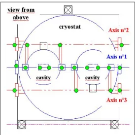
Figure 13: Test-bench for measurement of cavity displacements during cool-down
Figure 11: Target arm fixtures for transferring beam axis of the cavity B
Figure 12: Axis located on the helium tank with respect to the measured cavity axis Figure 10: Target arm fixtures for transferring
beam axis of the cavity A
0.50 m
Figure 14: Measurement of cavity displacements,
CONCLUSIONS
The alignment of the superconducting cryomodules will be a challenge, especially for transferring beam axis outside both the cavities and the cryostats. During this fiducialization process, we should make corrections on the fiducials positioning according to observed displacements during vacuum tests and cooling down. These external references will allow the alignment of one cryomodule cavity with respect to the others.
Presently, three techniques are discussed to align the straightness of the linac:
• Using laser alignment or the micro-Alignment Telescope (MAT) with a CCD camera. They give both horizontal and vertical deviations simultaneously
• using a tacheometer combined with a digital level • Using a laser tracker.
We have designed a test-bench to evaluate the performances of the alignment laser and of the Micro-Alignment Telescope (MAT) with its CCD camera. It has been used to adapt the procedures for the measurements and to validate the methods which will be used for the alignment of the linac components. Today, due to a lack of availability from suppliers, the MAT has not yet been tested.
The major parts of the superconducting SPIRAL2 accelerator devices are now under construction. The design of the building is under way and its construction will start in 2009.
ACKNOWLEDGEMENT
I would like to acknowledge all members of the GANIL design offices, as well as the colleagues from the
other laboratories involved in this project, particularly from IPN ORSAY and the DAPNIA Saclay.
REFERENCES
[1] A. Mosnier, The SPIRAL2 Project, APD Report, Survey System, Chapter VII-17 to VII-20, EDMS n°004609, January 2005
[2] R. Beunard, SPIRAL2 Accelerator-Survey and Alignment Concept, Poster, SPIRAL2 2 Week, Nov. 2007
[3] A. Mosnier, The SPIRAL2 Project, APD Report, Cryomodules, Chapter III-11 to III-27, EDMS n°004609, January 2005
[4] R. Beunard, Test cryomodule A: transfer of the cavity beam axis, internal note, EDMS n° 010375, March.2007
[5] R. Beunard, Test cryomodule B: transfer of the cavity beam axis, internal note, EDMS n° 011823, Nov.2007
[6] R. Beunard, Survey Cryostats at 4K, internal note, EDMS n° 003340, April 2004
Figure 15: Drawing showing the points to be measured