Characterization of Composites with Aligned Carbon
Nanotubes (CNTs) as Reinforcement
by
Enrique J. García
B.Eng + M.Eng. (Mechanical) Universidad de Zaragoza, Spain
DEA (Mechanical)
Universidad de Zaragoza, Spain; Université de Pau, France; École de Mines de Douai, France; University of North London, UK Submitted to the Department of Aeronautics and Astronautics
in partial fulfillment of the requirements for the degree of Master of Science in Aeronautics and Astronautics
at the
MASSACHUSETTS INSTITUTE OF TECHNOLOGY May 2006
© 2006 Enrique J. García. All rights reserved.
The author hereby grants to MIT permission to reproduce and to distribute publicly paper and electronic copies of this thesis document in whole or in part in any medium
now known or hereafter created.
Author ………. Department of Aeronautics and Astronautics May 20, 2006 Certified by ………
Brian L. Wardle Boeing Assistant Professor Thesis Supervisor Accepted by ………. Jaime Peraire Professor of Aeronautics and Astronautics Chair, Committee on Graduate Students
Characterization of Composites with Aligned Carbon Nanotubes
(CNTs) as Reinforcement
by
Enrique J. García
Submitted to the Department of Aeronautics and Astronautics in partial fulfillment of the requirements for the degree of
Master of Science in Aeronautics and Astronautics
Abstract
Carbon nanotubes’ (CNTs) superlative combination of electrical, thermal, and especially mechanical properties make them ideal candidates for composite reinforcement. Nanocomposites and hybrid composite architectures employing traditional advanced composites and CNTs offer significant potential mechanical and multifunctional performance benefits. CNT/polymer composites and two different hybrid architectures are experimentally investigated in this work. A novel process for rapidly growing dense, long, high-quality aligned CNT forests is employed. The first architecture is comprised of aligned fibers with CNTs grown radially on their surface. For the second architecture, dense forests of vertically aligned CNTs are placed between the plies of a laminate, in the through-thickness direction. Fundamental issues related to realizing hybrid composite architectures are investigated experimentally: wetting of the CNTs by commercially available polymers for the different architectures, effective reinforcement of the polymer matrices due to the addition of CNTs, and retention of mechanical (stiffness and strength) properties of the fibers after the CNT growth process. Wetting of CNT forests by several commercial polymers (including a highly-viscous epoxy) is demonstrated at rates conducive to creating a fully-dispersed CNT/matrix region for the two hybrid architectures previously described. Direct measurements of the mechanical properties of nanocomposites are reported for the first time in the literature. Increases in the Young’s modulus of the polymer as high as 220% with just 2% volume fraction of aligned CNTs are observed. Equivalent reinforcement had been obtained previously by other authors with 5% volume fraction of randomly oriented CNTs. Single-fiber tension tests indicate no mechanical degradation (stiffness and strength) for alumina fibers undergoing the CNT growth process. Preliminary results on the fabrication of the two hybrid architectures are also presented. All the experimental results presented in this work indicate that hybrid CNT/composite architectures are feasible and future work focuses on mechanical and multifunctional property characterization of these and other hybrid architectures, and scaling to a continuous CNT growth process.
Thesis Supervisor: Brian L. Wardle Title: Boeing Assistant Professor
Acknowledgments
This thesis would not be complete without thanking everyone that helped me and supported me for the last two years. It is impossible to put into words my gratitude to all of you, so, please, excuse me if I am not able to transmit my appreciation in these few lines.
First to my supervisor, Brian L. Wardle, who has not only been the most effective anchor during my research, but also a true colleague in this endeavor: thank you for your guidance and especially for your positiveness and support when results were elusive. Thank you for believing in this project and in me, and for everything I have learnt from you. Your dedication, motivation, and insight have been fundamental in the success of this project. I wish you all the best in the future.
Second, to the people who worked with me at different points of the research, thank you for your motivation and insight: to A. John Hart, Sunil D. Gouda, and Katrina Sorensen. This would not have been possible without your work and dedication.
To Alan Schwartzman from MIT´s Nanolab, Kurt Broderick and the rest of the staff at MTL, and especially to John Kane from TELAMS, thank you so much for your invaluable help to develop the processes and tests that conform this research. Your insightful knowledge and hands-on experience make MIT excel.
Next, I would like to thank the people who had to deal with me every day (and some nights): my lab mates. Thank you all for the support and advice, the hard work and the laughs we shared.
To my friends, here, in Spain, and around the world, thank you for your constant support at every moment, especially in the downsides. Thank you for never letting me down.
To my family, who has been behind me from the very beginning and supported me when I decided to completely change my life moving from industry back to school. Thank you for your love and support through the years and for letting me live my dream.
Of course, to Ana, I will never be able to thank you enough for sharing with me this amazing experience at the other end of the phone, for your endless support and for believing in me. I hope I will be able to repay you and to let you know how much all your help has meant to me in the past and especially over the last two years!
Last, and most importantly, I want to thank the Lord my God, who has given me both the ability and opportunity - undeserving - to live my dreams.
The author would like to acknowledge the Fundación La Caixa, which awarded the scholarship that has made all this possible.
Dedico este trabajo a mi familia al completo, por el infinito apoyo que he recibido en todo momento y en especial a mi madre, a mi padre, a mi hermana y a Ana, mi paciente
novia. ¡Esto no hubiese sido posible sin vosotros!
This work is dedicated to my entire family, for the infinite support they transmitted me all the time, and especially to my mother, my father, my sister, and my patient girlfriend,
Contents
Chapter 1.
Introduction...21
1.1 Composites Using Carbon Nanotubes (CNTs) ... 21
1.2 Overview of Thesis ... 23
Chapter 2.
Literature Review ...27
2.1 Carbon Nanotubes: Description, Processing and Characterization ... 27
2.1.1 CNT Structure... 28
2.1.2 Processing... 29
2.1.3 Mechanical Properties Characterization ... 32
2.2 CNTs/Polymer Composites: Description, Processing and Characterization ... 40
2.2.1 Long Fibers Containing Carbon Nanotubes ... 42
2.2.2 CNT/Polymer Composites... 45
2.2.3 Hybrid Composites ... 54
2.3 Summary ... 58
Chapter 3.
Fabrication and Testing of Composites of CNTs and
Polymers ...61
3.1 Introduction... 61
3.2 Growth of Carbon Nanotubes on Silicon Wafers ... 63
3.3 Wetting of CNTs with Different Commercial Epoxies... 68
3.3.1 Experimental Methods... 68
3.3.2 Results and Discussion ... 75
3.3.3 Summary of Wetting Results... 90
3.4 Mechanical Characterization Using Nanoindentation ... 92
3.4.1 Experimental Methods... 94
3.4.1.1 Microfabrication of CNT Films and Pillars ... 96
3.4.1.2 Berkovich and Spherical Indentation of Films... 101
3.4.2 Results and Discussion ... 111
3.4.2.1 Results Using EpoThin as Matrix ... 111
3.4.2.2 Results Using SU-8 as Matrix... 127
3.5 Summary of Nanocomposite Testing... 141
Chapter 4.
Fabrication and Testing of Hybrid Composites ...145
4.1 Introduction... 145
4.2 Hybrid Composites Using CNTs Grown on the Fibers’ Surface... 146
4.2.1 Growth of Carbon Nanotubes on the Surface of Alumina Fibers... 148
4.2.2 Single Fiber Tensile Test ... 150
4.2.2.1 Experimental Methods ... 150
4.2.2.2 Results and Discussion... 153
4.2.3 Summary... 156
4.3 Hybrid Laminated Composites Using CNTs at the Interface between Plies ... 157
4.3.1 Growth of Carbon Nanotubes on Silicon Wafers ... 158
4.3.2 Wetting of CNT Forests on Graphite Fiber/Epoxy Prepregs ... 160
4.3.2.1 Experimental Methods ... 160
4.3.2.2 Results and Discussion... 162
4.3.3 Summary... 173
4.4 Summary of Hybrid Composites... 173
Chapter 5.
Conclusions and Recommendations...175
5.1 Contributions... 175
5.2 Recommendations... 180
List of Figures
Figure 2.1: Extremes of CNT atomic structure (i.e., chirality) of (a) zig-zag and (b) armchair single-walled CNTs. Spheres represent Carbon atoms, whereas the lines connecting the spheres represent carbon-carbon bonds... 29 Figure 2.2: Stone-Wales transformation... 34 Figure 2.3: Specific strength vs. specific modulus for the most common materials
compared to CNTs. Chart modified from Ashby’s plots [113]. ... 39 Figure 3.1: SEMs of a) CNT pillars grown on patterned catalyst on silicon substrate
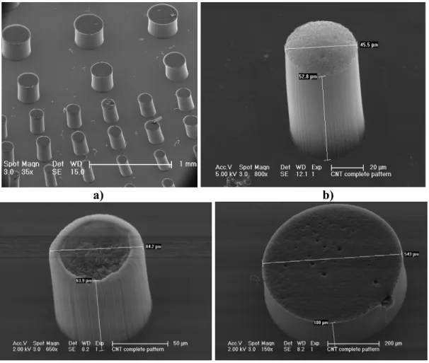
(scale bar is 500 μm); b) Close-up of a single pillar; c) Alignment of the CNTs... 65 Figure 3.2: TEM image of the MWCNTs (scale bar = 10 nm). ... 66 Figure 3.3: SEMs of a) CVD-grown CNT pillars on Si wafer surface; b), c), d) Pillars of
different sizes made of pure CNTs. ... 67 Figure 3.4: SEMs of a) from left to right, hexagonal, square, and triangular CNT-pillars;
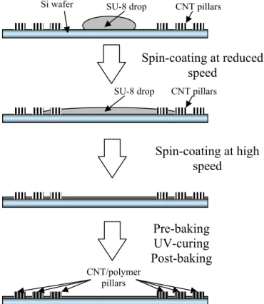
b) Detail of a square pillar. ... 67 Figure 3.5: Illustration of the process used in the first two sets of tests to wet the CNTs
with the highly viscous epoxy... 70 Figure 3.6: Illustration of the process used in the third set of tests to wet CNT pillars with
the SU-8 resin. ... 71 Figure 3.7: Equipment used to spray SU-8 on the CNT pillars while spin-coating in the
fourth set of tests... 73 Figure 3.8: Scheme of the new submersion method used in the fifth set of tests to wet the
CNT pillars with the SU-8 and EpoThin resins. Possible wetting routes are
illustrated in the inset at right... 74 Figure 3.9: SEM of a) layer of SU-8 2025 on top of a CNT forest; b) Closer image of the
Figure 3.10: SEMs of a) 1-mm high CNT-pillars wet by conductive epoxy; b) Close up of the wet region at the base of the pillar; c) and d) closer views of the wet region at the pillar base... 77 Figure 3.11: SEMs of a) Dry 100-µm high CNT-pillars; and top-down views of CNT
pillars transplanted to the glass/epoxy substrate: b) Nanocomposite film made of CNT pillars wet by conductive epoxy; c) Close up of a wet pillar; d) Cross-section of a wet pillar. ... 78 Figure 3.12: SEMs of a) Dry CNT pattern; b) Cross-section of the CNT/SU-8 feature
showing good wetting; c) Close up of the top region of the cross section; d) Wetting of the CNTs... 79 Figure 3.13: SEMs of a) Pillar with SU-8 2005 drops on the surface showing the
somewhat hydrophobic nature of the CNT forest sidewalls; b) CNT-pillars pattern wet using the spraying method and a lower viscosity SU-8 (SU-8 2002); c) Pillar fully wet by the SU-8 drop at its base (extremely irregular contraction); d) Drops of SU-8 effectively penetrating the CNT pillar sidewall, but the quantity of SU-8 penetrating the structure was not enough to fully wet the pillar... 81 Figure 3.14: SEM of pillar fully-wet using SU-8 2000.1. The pillar is highly contracted
(the original diameter of the pillar is shown by the dark circle around the base of the pillar), however the regularity of the contraction produced during wetting
maintained the cylindrical shape... 82 Figure 3.15: SEMs of pillars wet using SU-8 2002: a) Pattern of fully-wet cylindrical
nanocomposite pillars; b) 80-µm diameter cylindrical pillar of; c) Triangular
nanocomposite pillar; d) Hexagonal nanocomposite pillar with preserved shape.... 83 Figure 3.16: SEMs of a) Vertically cross-sectioned nanocomposite pillar; b) Zoom-in of
the cross-section surface of the pillar showing the effective wetting of the CNTs. Note that the alignment of the CNTs is maintained during wetting which is visible particularly at the sidewalls. ... 84 Figure 3.17: SEMs of a) Cylindrical pillar wet by SU-8 2002; b) Square pillar wet using
SU-8 2002; c) Highly contracted cylindrical pillar wet by SU-8 2000.1; d)
Hexagonal pillar wet by SU-8 2000.1 (note the regularity of the contraction and the alignment of the CNTs even after the extreme contraction and folding); e)
Cylindrical pillar wet by EpoThin low viscosity epoxy; f) Star-shaped long pillar wet using EpoThin. ... 86 Figure 3.18: SEMs of a) Pillar of CNTs after being wet by SU-8 2002 epoxy resin; b)
Same pillar after microtoming its top surface; c) Zoom-in of the microtomed surface of the pillar; d) Closer view of the microtomed surface, showing complete wetting. ... 87
Figure 3.19: SEMs of a) Microtomed pillar with cell structure; b) Closer view of the multiple cells formed during wetting; c) Another microtomed pillar with 2 large voids created during wetting with SU-8 2002; d) Closer view of the voids. Note the
effective wetting (no micro-voids) around the voids... 88
Figure 3.20: SEMs of a) dense forest of CNT completely wet after submerging the wafer in SU-8; b) diesawed cross-section of the wet forest (note the alignment of the CNTs)... 89
Figure 3.21: Illustration of compression test of an aligned CNT nanocomposite using a nanoindenter... 95
Figure 3.22: SEMs of a) side view of a representative CNT/EpoThin pillar before applying the compression test; b) Top view of the same pillar, showing the cell structure created by the EpoThin during wetting... 97
Figure 3.23: SEMs of a) pattern of large pillars for Berkovich nanoindentation; b) 40- μm diameter SU-8 pillars used in the compression tests. ... 99
Figure 3.24: SEMs of a) CNT/SU-8 nanocomposite pillars with relatively well controlled contraction; b) top view of the same pillars; c) regularly contracted CNT/SU-8 pillar (note the crown formed during contraction); d) top view of the same pillar, showing the regular contraction and the verticality of the pillar after wetting. ... 100
Figure 3.25: Micro Materials Nanotest micro- and nanoindenter... 102
Figure 3.26: a) Schematic of the Micro Materials Nanotest design; b) Close-up view of the indenter, where it is possible to identify the most important parts of the of the pendulum system. ... 103
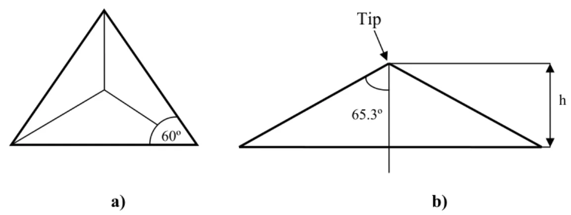
Figure 3.27: a) Top and b) side views of the geometry of the Berkovich indenter. ... 105
Figure 3.28: Schematic of the geometry of spherical indentation. ... 106
Figure 3.29: Illustration showing the analysis for unloading. Adapted from [126]. ... 107
Figure 3.30: Schematic of the geometry of compression test using a flat punch nanoindenter. The contact area between the flat punch and the pillar is the surface area of the pillar’s top surface... 110
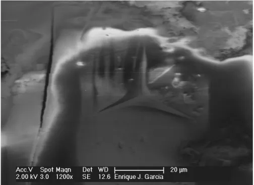
Figure 3.31: Berkovich indent on the surface of a CNT/EpoThin film. ... 112
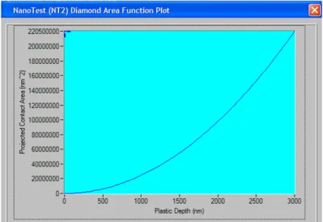
Figure 3.32: Projected contact area as a function of the penetration depth for a Berkovich indenter used by Micro Materials’ analysis software. ... 113
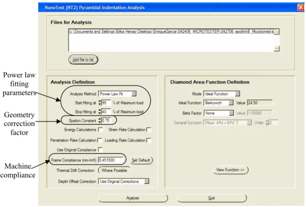
Figure 3.33: Indentation analysis parameters for the Micro Materials’ analysis software. ... 114
Figure 3.34: Typical power-law fitting analysis parameters for the Micro Materials’ analysis software. In this case, fitting for a Berkovich indentation on the surface of a pure EpoThin film... 114 Figure 3.35: Representative Load-Depth curves for Berkovich nanoindentation of
unreinforced (thin blue line) and CNT-reinforced EpoThin (thick magenta line) films. ... 115 Figure 3.36: Projected contact area as a function of the penetration depth for a spherical
indenter used by Micro Materials’ analysis software. The linear term found in
equation (3.5) dominates the quadratic term... 118 Figure 3.37: Representative Load-Depth curves for spherical nanoindentation of
unreinforced (thin blue line) and CNT-reinforced EpoThin (thick magenta line) films. ... 119 Figure 3.38: SEM images of a) microtomed CNT/EpoThin nanocomposite pillar; b) top
view of the pillar, showing the cellular structure formed in the interior of the pillar during wetting; c) pillar after compression test (note that the cellular structure has been flattened out during the test); d) closer view of the flattened honeycomb
structure... 122 Figure 3.39: Illustration of process used to calculate the effective area of the
nanocomposite pillars subjected to compression tests: a) SEM top view image of the microtomed pillar with the perimeter highlighted; b) total surface area of the pillar. ... 123 Figure 3.40: Illustration of process used to calculate the effective area of the
nanocomposite pillars subjected to compression tests: a) SEM top view image of the microtomed pillar with the effective perimeter highlighted; b) effective surface area of the pillar... 124 Figure 3.41: Representative stress-strain curve for the CNT-reinforced EpoThin pillars
under compression using the total surface inside the perimeter (thin blue line) and the effective surface area (thick magenta line). The elastic region used to calculate the elastic modulus is highlighted... 125 Figure 3.42: Representative load-depth curve of Berkovich nanoindentation test
performed on a CNT-reinforced SU-8 film. Creep appeared during the initial part of the unloading phase, as highlighted, making the Oliver-Pharr analysis of the results invalid. ... 128 Figure 3.43: Berkovich indent on the surface of an unreinforced SU-8 film. ... 129 Figure 3.44: Representative load-depth curve for a Berkovich nanoindentation test on
Figure 3.45: Representative load-depth curve for a compression test on an unreinforced SU-8 pillar... 132 Figure 3.46: Pillars broken at the base due to slight variations in their verticality and/or
irregular contraction... 134 Figure 3.47: Representative load-depth curve for imperfect pillars. The illustration shows
an initial rupture point and additional displacement of the indenter while the
maximum load is held for 60 seconds... 135 Figure 3.48: SEM images of a) vertical CNT/SU-8 nanocomposite pillar; b) top view of
the pillar, showing verticality and regular contraction; c) pillar after compression test (note that the dome has been flattened out during the test); d) closer view of the flattened dome... 137 Figure 3.49: Representative load-depth curve for good compression tests. The illustration
shows the initial phase where the dome is flattened (1), the formation of the cracks (2), and a change in slope once the CNT/SU-8 nanocomposite below the dome takes the load (3). ... 138 Figure 3.50: SEM images of a) vertical CNT/SU-8 nanocomposite pillar; b) pillar after
compression test (note that the dome has been flattened out during the test)... 139 Figure 3.51: Load-depth curve obtained for the pillar shown in Figure 3.50... 139 Figure 4.1: SEMs of a) Pure alumina fibers; b) Close-up of pure alumina fibers. ... 148 Figure 4.2: SEMs of a) Alumina fibers with CNTs grown on their surfaces; b) Closer
view of the alumina fiber bundle with CNTs grown on the surface; c) Alumina fiber (shadow behind CNTs) with well-aligned, 30-μm long CNTs grown on its surface; d) Alignment of the CNTs grown on the surface of alumina fibers. ... 149 Figure 4.3: (top to bottom) Bundles of pure alumina fibers, fiber bundles soaked in
catalyst, and fiber bundles with CNTs grown on their surfaces. ... 151 Figure 4.4: a) Tab with a single alumina fiber with CNTs grown on its surface mounted
on the microtester ready to start the tensile test; b) closer view of the assembly before starting the test... 152 Figure 4.5: Typical single-fiber stress-strain curves... 154 Figure 4.6: Weibull probability distribution for the tensile strength of the pure alumina
fibers, fibers soaked with catalyst and fibers after the CNT growth process. ... 155 Figure 4.7: SEM of cross-section of a vertically aligned CNT forest grown using the
thermal CVD process (Scale bar 70 µm). ... 159 Figure 4.8: Diagram of the nano-stitching fabrication assembly (not to scale)... 161
Figure 4.9: Large regions without CNTs transplanted. Two small regions (inside white circles) with CNTs transplanted are evidence of irregular wetting. ... 162 Figure 4.10: Close-ups of the irregularly wet region shown in Figure 4.9 (bottom right):
a) General view; b) Close-up of the wet base of the pillars connected to the fibers of the prepreg; c) Closer view of the wet region at the base of the pillars... 164 Figure 4.11: a) Close up of the honeycomb structure shown in Figure 4.9 (top left); b)
Closer view of the cells with thin (~2 µm) aligned CNT nanocomposite walls... 165 Figure 4.12: Wetting of forests transplanted to the prepreg using the second testing
method (CNTs in contact before heating the prepreg): a) Transplanted CNTs with wetting only at the base; b) Larger transplanted region of forest with CNTs
completely wet and forming a regular honeycomb-like pattern. ... 166 Figure 4.13: SEMs of a) completely wet CNTs creating honeycomb structures slightly
thicker than in the previous set of tests (~4-5 µm); b) nanocomposite honeycomb region with maximum ~10-µm thick cell walls... 167 Figure 4.14: SEM of the interconnection of the nanocomposite and the fibers in the
prepreg. ... 168 Figure 4.15: SEM of catalyst layer strongly adhered to the nanocomposite (and attached
to the prepreg) and separated from the original Si substrate with this layer... 169 Figure 4.16: SEM of larger regions of transplanted CNTs: completely wet (center), and
wet at the base, but not to the top of the CNTS (left region)... 170 Figure 4.17: SEM of larger regions of completely wet transplanted CNT forming
regularly spaced honeycomb structures. ... 170 Figure 4.18: SEM of the hybrid composite cross section generated by the disco abrasive
system. The fully wet CNT/epoxy honeycomb structure is well adhered to the
prepreg ply. ... 171 Figure 4.19: SEMS of a) Close-up of the diesawed region connecting the wet CNT
honeycomb structure with the prepreg layer; b) Closer view of the region
List of Tables
Table 2.1: Commonly referenced mechanical properties of CNTs (Øint and Øext
correspond to inner and outer diameter respectively)... 38 Table 2.2: Comparison of mechanical properties of CNTs, carbon, and Kevlar fibers and
high-tensile steel [50], [71]. The values for the CNT were taken for a SWCNT of diameter 10 nm, using the entire area enclosed by the tube to normalize
stiffness/strength. ... 38 Table 3.1: Test matrix of successful CNT wetting tests performed. ... 69 Table 3.2: Test matrix of mechanical nanocomposite tests. ... 94 Table 3.3: Comparison of mechanical properties (Young’s modulus and hardness) for
unreinforced EpoThin and CNT/EpoThin nanocomposite films obtained from
Berkovich nanoindentation tests (12 tests). ... 116 Table 3.4: Comparison of mechanical properties (Young’s modulus and hardness) for
unreinforced EpoThin and CNT/EpoThin nanocomposite films obtained from
spherical nanoindentation tests (12 tests). ... 119 Table 3.5: Comparison of the Young’s modulus of CNT-reinforced EpoThin pillars
obtained from Oliver-Pharr’s curve fitting for the unloading and from the analysis of the stress-strain curve during loading (10 tests). ... 125 Table 3.6: Young’s modulus and hardness obtained from Oliver-Pharr’s curve fitting for
the unloading phase of Berkovich nanoindentation tests on pure SU-8 films for the two different loading rates (20 tests at 2 mN/s, 8 tests at 7 mN/s). ... 131 Table 3.7: Comparison of the Young’s modulus of unreinforced SU-8 obtained from
Berkovich indentation of pillars, and from compression tests of pillars using two different techniques: modified Oliver-Pharr’s curve fitting for the unloading and the analysis of the stress-strain curve during loading. ... 133 Table 3.8: Dimensions of the 6 CNT/SU-8 Pillars Successfully Tested in Compression.
Table 3.9: Comparison of the Young’s modulus of unreinforced SU-8 and CNT/SU-8 pillars obtained from compression tests... 140 Table 4.1: Experimental modulus and strength results for pure alumina fibers, fibers
soaked with catalyst and fibers after the CNT growth process... 153 Table 4.2: Weibull parameters for the tensile strength of alumina fibers... 155
List of Symbols
Symbol Description Units
D0 External diameter in a MWCNT [nm]
Eb Bending elastic modulus of a CNT [GPa]
Ea Axial elastic modulus of a CNT [GPa]
Ew Wall elastic modulus of a CNT [GPa]
Øint Diameter of the inner wall of a MWCNT [nm]
Øext Diameter of the outer wall of a MWCNT [nm]
H Material hardness [GPa]
Pmax Maximum load applied by the nanoindenter [mN]
A Projected area of indentation [nm2]
hp Depth of penetration (Berkovich nanoindentation) [nm]
θ Face angle of the indenter [deg]
a Radius of the circle that defines the contact area in spherical nanoindentation
[µm]
R Radius of the spherical indenter [µm]
S Contact stiffness in nanoindentation unloading [N/m]
P Load applied by the nanoindenter [mN]
β Nanoindentation geometry constant -
Er Reduced elastic modulus for nanoindentation [GPa]
E Longitudinal Young’s modulus of the specimen [GPa]
Ei Isotropic Young’s modulus of the indenter [GPa]
ν i Isotropic Poisson’s ratio of the indenter -
ε Geometry correction factor for nanoindentation -
Enanocomp Longitudinal Young’s modulus of the nanocomposite [GPa]
ECNT Longitudinal Young’s modulus of the CNT [GPa]
VCNT Volume fraction of CNTs -
Ematrix Isotropic Young’s modulus of the polymer matrix [GPa]
dnc Diameter of the nanocomposite pillar after contraction [µm]
Dnc Diameter of the nanocomposite pillar at its base (original
diameter of the CNT pillar)
[µm]
hnc Height of the regularly contracted part of the
nanocomposite pillar [µm]
Hnc Height of the transition region of the nanocomposite
pillar
[µm]
x Stress [MPa]
p(x) Probability of failure of the fiber at a particular stress, x
S Standard deviation of tensile strength [MPa]
x
Average tensile strength [MPa]α Scale factor of the Weibull distribution -
Chapter 1. Introduction
1.1 Composites Using Carbon Nanotubes (CNTs)
Carbon nanotubes (CNTs) have been the focus of considerable research since their discovery by Iijima in 1991 [1]. Numerous studies have proven their impressive electronic properties, such as a capacity of carrying electric current 1000x higher than copper wires [19]-[20]. CNTs also have outstanding thermal properties. Ruof and Lorents measured thermal stability up to 2800 ºC, and thermal conductivity about twice as high as diamond [21]. These properties have been investigated for electronic devices. In addition to the exceptional electronic and thermal properties associated with carbon nanotubes, they also posses exceptional mechanical properties [22]-[44]: Theoretical and experimental results point to an elastic modulus higher than 1 TPa, compared to 0.2 TPa for steel and 0.07 TPa for aluminum, and strengths 10 to 100 times higher than the strongest steel at a fraction of the weight [2]. Due to their remarkable mechanical properties many researchers have focused on using carbon nanotubes as reinforcement for different materials.
Reinforcement of different matrices through the use of carbon nanotubes and nanoclays has been a major focus of research around the world. The problems associated with large filler particles (mainly stress concentrations) are considerably reduced due to
the size of the nanotubes. Moreover, no other filler provides such a high strength and stiffness combined with a low density. Analytical models and extensive work on reinforcement of polymer, ceramic, and metal matrices have been developed in the last few years.
Carbon nanotubes have also been studied as reinforcement for traditional composite materials. The outstanding mechanical properties of composite materials have allowed them to increase their presence in the aeronautical industry in the last 20 years. Composite materials have mechanical properties comparable to those of the best metal alloys but with about a third of the weight. Because of their exceptional in-plane mechanical properties, multilayered composite materials are effectively used in structural parts traditionally reserved for metal alloys. However, the relatively poor mechanical properties of the matrix and the fiber/matrix interfacial bond limit their use in particularly demanding applications. Composite materials fail through numerous modes at various lenghtscales. Carbon nanotubes increase the capacity of load transfer between matrix and fiber: On the one hand, they reinforce the matrix, increasing its load-carrying capability; on the other hand, they increase the effective interface area, favoring the load transfer.
Composite laminates contain matrix-rich regions that reduce their overall performance. In composite laminates, the thin, unreinforced pure matrix layer that exists between plies has poor mechanical properties (stiffness, strength, fracture toughness) when compared to in-plane properties of the laminate. Delamination and matrix cracking between plies are the dominant modes of damage and therefore responsible for the reduction of properties in the direction normal to the plane. In recent years several different solutions have tried to overcome this limitation: 3D-braiding, weaving and
stitching (e.g., z-pinning) are the most promising solutions to date. All these processes increase to some extent the through-thickness mechanical properties of layered composite materials, but also reduce the laminate’s performance in the in-plane directions of the laminate [75]-[83]. A possible method to increase a composite’s resistance to delamination without compromising the in-plane properties is the use of carbon nanotubes (CNTs) in the interface between layers that would not only improve the mechanical properties of the inter-ply region, but also can help reduce the crack propagation by bridging the two plies across the crack.
1.2 Overview of Thesis
The focus of this research is on exploiting CNT’s outstanding nanoscale properties toward the development of macroscopic structural materials. This work focuses on polymer-matrix composites because of the extensive number of present applications. As mentioned previously, carbon nanotubes have superior mechanical, electrical, and thermal properties, which make them a perfect candidate for multifunctional composite materials. Though the study of multifunctional composites using carbon nanotubes is extremely interesting, there are too many unknowns in their design that must be solved before being able to take full advantage of the outstanding combination of properties that carbon nanotubes offer. Importantly for this research, the mechanical properties of CNT/polymer and CNT/polymer/fiber composites have not been completely determined yet. Taking all these considerations into account, the focus of this research is the mechanical characterization of polymer based composites using
carbon nanotubes and their possible use in structural applications. Specific objectives of this project are:
• Preliminary investigation of the wide potential of the CNTs for mechanical reinforcement. The wide potential stems from the numerous architectures of CNT/polymer matrix/advanced fibers that have been identified.
• Determine experimentally the effectiveness of the wetting of carbon nanotubes by different polymer matrices, using different wetting processes and polymers. • Obtain direct measurements of the mechanical properties (Young’s modulus and
strength) of CNT/polymer nanocomposites.
• Explore two different architectures for hybrid composites containing carbon nanotubes, advanced fibers, and polymer matrices.
• Develop experimental setups and fabrication processes for several hybrid architectures to verify their feasibility.
• Develop fabrication and characterization of hybrid multilayered composites containing CNTs in the plies’ interface. This research will also address the viability of a continuous process to fabricate CNT-reinforced prepregs.
The approach taken in this work is mainly experimental. Wetting of the CNTs with different polymer matrices were studied on CNTs grown in the form of dense forests and also in the form of pillars of different sizes and shapes. The mechanical properties of the CNT/polymer nanocomposites were tested using a nanoindenter and a flat punch to apply a compression test on nanocomposite (CNT/polymer) pillars. Two different hybrid architectures were studied to address the issues associated with traditional composites
described previously: Forests of carbon nanotubes placed vertically between plies of traditional composite materials, and carbon nanotubes grown on the surface of advanced fibers and wet by a polymer matrix. For both hybrid architectures the wetting of the CNTs with polymer matrices was carefully explored experimentally.
The following aspects fall outside the scope of the current project:
• Ceramic- and metal-matrix composites are not considered here, but numerous studies have established possibilities of improvement on both types of composites [4]-[6].
• The study of electrical and thermal properties of carbon nanotubes or composites containing carbon nanotubes.
• A thorough study of CNTs used in multifunctional applications. As mentioned previously, answering fundamental questions about the mechanical properties of these nano- and hybrid composites is considered to be most important.
This work will first present a thorough review of previous analytical and experimental results in the processing and mechanical characterization of pure CNTs and composite materials based on CNTs: CNT/polymer nanocomposites and hybrid composites (CNT/polymer matrix/advanced fiber composite materials). Second, the work will present results obtained in this research for the fabrication and mechanical characterization of nanocomposites using different commercially available polymer matrices. Third, preliminary results regarding the feasibility of the manufacturing of two promising hybrid architectures will be presented. Finally, conclusions will be extracted together with recommendations for future work.
Chapter 2. Literature Review
In this chapter, research into processing, characterization and modeling of carbon nanotubes (CNTs) and their composites (polymer matrix focus) is reviewed. The chapter is divided into two major parts that address two related issues: First, a review of the research focused on CNTs themselves, their fabrication and characterization, to fully understand their possible applications; second, a comprehensive review of the literature related to CNT-based polymer composites, the effectiveness of the reinforcement, and known issues. As mentioned in Chapter 1, the focus will be on polymer-matrix composites, the characterization of their mechanical properties and their application as structural materials.
2.1 Carbon Nanotubes: Description, Processing and
Characterization
CNTs have a combination of outstanding mechanical, electrical, and thermal properties that make them eligible for numerous applications. Being interested in structural applications for CNT composites, a better understanding of their molecular structure, the manufacturing processes that allow their fabrication (growth), and the effect that both structure and process have on the CNT’s mechanical properties are
fundamental. Electrical and thermal properties of the nanotubes are also interesting for other applications and have been the focus of numerous studies. However, as the focus of this research is the structural applications of carbon nanotubes, these studies are not included in the present review.
2.1.1 CNT Structure
Graphite is a 2-D sheet of carbon atoms arranged in a crystalline hexagonal structure held together by strong covalent bonds. The sheets are layered and very weakly held together by van der Waals forces. Carbon nanotubes are usually described as a sheet of graphite rolled into a perfect tube. As in the case of graphite, each carbon atom has 2 single (C-C) and one double (C=C) covalent bonds. Nanotubes, or CNTs, can usually be divided into two groups: single-walled and multi-walled nanotubes (SWCNT and MWCNT, respectively). This is in contrast to nanofibers, nanofilaments, and nanorods, which are not rolled structures of carbon, but more weakly arranged. SWCNTs can be thought of as rolling a single layer of graphite, whereas MWCNT consist of several concentric SWCNTs, believed to be held together primarily by Van der Waals forces (second order forces, relatively weak compared to carbon-carbon bonds). The structure of a carbon nanotube is described by its chirality. This property defines how the sheets of graphite are “rolled” into a tube, based on the geometry of the carbon bonds around the circumference. The two limit values of the chiral angle are 0 degrees (the so-called zig-zag structure) and 30 degrees (armchair structure). The intermediate cases are usually called chiral nanotubes [2]. The structures of the two limit values mentioned previously,
zig-zag and armchair, are shown in Figure 2.1. The influence of chirality on the mechanical properties of CNTs is discussed in section 2.1.3.
(a) Zig-zag SWCNT (b) Arm-chair SWCNT Figure 2.1:Extremes of CNT atomic structure (i.e., chirality) of (a) zig-zag and (b) armchair single-walled CNTs. Spheres represent Carbon atoms, whereas the lines
connecting the spheres represent carbon-carbon bonds.
2.1.2 Processing
Carbon nanotubes are synthesized using a wide variety of different techniques, such as arc-discharge [7]-[9], laser ablation [10]-[11], gas-phase catalytic growth from carbon monoxide [12]-[13], and chemical vapor deposition (CVD) [14]-[18]. The first two methods (arc-discharge and laser ablation) present important limitations to the large-scale production needed to successfully introduce these materials in structural applications: First, both methods have a finite carbon source which limits the volume of CNTs that can be produced. The gas-phase methods (catalytic growth from CO and
CVD) replace continuously the carbon source (gas), allowing continuous processing of CNTs. The costs associated with the production of large quantities of CNTs using arc-charge or laser ablation are viewed as high compared to the gas-phase techniques. Second, both methods produce a higher number of by-products or impurities than the CVD processes. The purification process needed to obtain carbon nanotubes amenable to be used in structural applications further increases the cost. Third, the temperatures needed for both processes, arc-discharge and laser ablation, are above 3000 ºC. The cost of the equipment and energy necessary to complete the processes is high when compared to the gas-phase methods, which require lower temperatures (below 1000 ºC). Finally, these processes tend to form ropes or bundles of nanotubes instead of detached CNTs. The effective mechanical properties of these ropes decrease considerably when compared to straight single nanotubes, as stated by Yu et al. [44]. Gas-phase methods, on the contrary, allow the synthesis of large quantities of detached carbon nanotubes that can be used immediately after the synthesis process.
The two gas-phase methods mentioned in the previous paragraph, catalytic growth and chemical vapor deposition, permit different approaches to the synthesis of CNTs. Gas-phase catalytic growth using CO as the carbon source is a refined process that enables the production of large quantities of very long and pure SWCNTs randomly oriented [12]. The technology has been commercialized for large-scale production [2]. Chemical vapor deposition (CVD) is also a large-scale production process with a relatively low price of production when compared to other processes. The CVD process requires the dissociation of a high-carbon-content hydrocarbon gas in the presence of a catalyst (a transition metal) at elevated temperatures (from 500 ºC to 900 ºC). It is
important to note that, as mentioned previously, the temperatures required for this process are well below the temperatures needed for arc-discharge or laser ablation (around 3000 ºC). After dissociation, carbon atoms are dissolved into the nanostructural catalyst, reaching a saturation point. The precipitation of carbon from the saturated catalyst nanoparticles results in the formation of carbon nanotubes [86]. Depending on the method used to obtain the high amount of energy required to dissociate the hydrocarbon gas precursor, the CVD processes can be divided into Thermal CVD or Plasma-Enhanced CVD. Thermal CVD uses heat to enable dissociation. PECVD uses heat as well as high energy electrons in plasma to dissociate the feed gas, and therefore requires significantly lower temperatures (~550 ºC) [87]. For both methods it is possible to localize the growth of CNT’s through controlled catalyst deposition. Plasma-enhanced chemical vapor deposition (PECVD) is a variation of the CVD process that allows the generation of large arrays of well-aligned single- and multi-walled CNTs [14]. This arrangement likely exploits CNTs mechanical properties to the maximum. Thermal Chemical Vapor Deposition requires a higher temperature in the process, but allows interesting variations with respect to PECVD. Using the right parameters it is possible to obtain dense forests or patterns of well-aligned thin carbon nanotubes (~10 nm in diameter). The main advantage of this process when compared to PECVD is that the thermal CVD allows faster growth rates (up to 2.5 μm/s, or 150 μm/min, compared to 2 μm/min for the PECVD process) and lengths of the CNTs that can go from several microns to several mm [84]. Zhu et al. recently obtained 4-cm-long single-walled CNTs using thermal CVD and reported their ability to grow even longer nanotubes [85]. The length limitations of the PECVD process are due to the rapid consumption of the catalyst. This problem can be
overcome by catalyzing the tips of the CNTs to create longer CNTs, but the re-catalyzing process creates defects that reduce the CNT’s mechanical properties.
The benefits of chemical vapor deposition over the other methods mentioned previously (arc-discharge, laser ablation and catalytic growth) can be summarized as:
• Ability for the growth of different types of nanostructures (tubes or wires) [25]. • Large area growth.
• Direct growth onto substrate (compared to the other methods that produce detached CNTs).
• Good alignment of the nanotubes produced.
• Control over variables like tube length (via time of exposure) and diameter (via control of the catalyst) [15].
Due to these advantages over the other processes, plasma-enhanced chemical vapor deposition (PECVD) and thermal chemical vapor deposition are the processes selected by many groups working on CNTs. Thermal CVD in this work.
2.1.3 Mechanical Properties Characterization
A good understanding of the properties of carbon nanotubes is critical in order to better understand the real applications that they can have. The characterization of carbon nanotubes, because of their reduced size, imposes considerable difficulties. The development of atomic force microscopy (AFM), Raman spectroscopy, transmission electronic microscopy (TEM), and X-ray scattering and tomography have allowed the characterization of carbon nanotubes and nanocomposites from the molecular level.
However, the results obtained from different studies using different techniques differ considerably. The focus of different studies has been on Young’s modulus and strength along the CNT axis. Little is known about the transverse properties of the CNTs, in part due to the complexity of the tests needed.
Chirality and its effects on CNTs properties, for example, have been the subject of controversy. Chirality, as mentioned before, defines how the sheets of graphite are “rolled” into a tube. All studies related to chirality agree that it has strong impact on the electronic properties of CNTs. Nanotubes can be either metallic or semiconductor, depending on their chirality. Armchair CNTs are metallic, whereas zig-zag CNTs are semiconductors. The influence of chirality on the mechanical properties of CNTs, however, is not so clear. Yakobson [29] used atomistic theories (molecular dynamics, MD) to model the different CNT structures (armchair, chiral, and zig-zag). According to those numerical results, the effect of chirality on the elastic stiffness is insignificant (below 1%). Lu [22] developed an empirical lattice dynamics model (used previously to model graphite layers by R. Al-Jishi and G. Dresselhaus [23]), that predicted that chirality does not affect the mechanical properties of CNTs. Opposed to this theory, other studies [58] hold that the exact magnitude of the mechanical properties depend on chirality, as well as the type of nanotube (single- or multi-walled), and its dimensions (diameter and length). It is interesting to mention that Yakobson [29] also used the model to simulate high strains applied to the carbon nanotubes. According to that analysis, CNTs allow, under tension, a Stone-Wales transformation (a reversible diatomic interchange that changes the structure from four hexagons to two heptagons and two pentagons in pairs). This transformation, shown in Figure 2.2, may explain the high
resilience and strain-to-failure without plasticity (5%) observed for carbon nanotubes [43], [88].
Figure 2.2:Stone-Wales transformation.
The measured mechanical properties of single- and multi-walled carbon nanotubes vary significantly from one study to the other, due somewhat to the indirect nature of the measurements. Another important factor that contributes to the scattered results is the difficulties in calculating the effective area of the nanotubes. Typically, CNTs are assumed to be cylindrical tubes with an inner and outer diameter. In the case of single-walled CNTs, this is a straight forward approximation. Multi-walled CNTs are sometimes treated as a solid cylinder or as a solid tube in the calculations (i.e., a cylinder having wall thickness equal to the difference between the outer and inner radii of the tubes) [107], and other times as a set of non-interacting concentric tubes [28].
Govindjee and Sackman [89] have discussed the validity of continuum mechanics in the estimation of nanotubes properties: First, they derived an expression to correct the error produced by homogenizing the cross section of a MWCNT, which in reality consists of discrete, separated layers of finite thickness. Second, they also pointed out that
5
7
5 7
“as the specimen size diminishes, the lattice spacing becomes important, and the discrete structure of the material can no longer be homogenized into a continuum.” According to this work, calculations for the area that transform the MWCNT into a solid material can only be considered as approximations. As mentioned previously, other studies [28] model MWCNTs as concentric tubes with a particular thickness and regular spacing between the walls. Even if CNT walls are not continuum, it is possible to approximate them to a continuum wall with an effective mechanical thickness. Different studies [29]-[30] have established, by comparing atomistic level simulations and shell theory, that the wall thickness ranges between 0.066 and 0.075 nm. The inter-wall spacing is maintained by weak van der Waals forces and has been measured to be between 0.34 and 0.39 nm [31]-[33]. The inter-wall spacing is considered to be constant during tensile and bending tests [34]-[35]. TEM measurements [36] seem to confirm the lack of interaction between the different walls of a MWCNT under bending.
Different experimental methods have been used to determine the Young’s modulus and the strength properties of the carbon nanotubes: measurement of the CNTs’ intrinsic thermal vibration, tension, compression, and bending tests using AFM tips, and compression tests using a nanoindenter are the most important methods used prior to this work. More recently Demczyk et al. were able to develop a tensile testing stage device using microfabrication techniques that allowed the application of tensile strain to individual CNTs while viewed in a TEM [88]. The highest values were obtained by Treacy et al. [24]. In that work, TEM was used to determine that the elastic modulus of MWCNTs was 1.8 TPa. However, this value was not obtained from a direct measurement, but from the study of the intrinsic thermal vibration of the nanotubes at
different temperatures. The MWCNTs were approximated as solid tubes with an inner and an outer diameter for the calculations. No results on strength were reported. Wong et
al. [25] used an atomic-force microscope (AFM) to directly measure the stiffness and
strength of a single MWCNT through a bending test. They pinned one end of the CNT and bent the other end by means of the AFM tip. The value for the elastic modulus was reported as 1.26 TPa, whereas the tensile strength value was 28.5 GPa. As in the previously mentioned paper by Treacy et al., a tube with an inner and an outer diameter was used as a representation of the MWCNT structure. Yu et al. [27] attached both ends of multi-walled CNTs to two opposing AFM tips and applied a tensile test. The failure mechanisms for multi-walled CNTs were micrographed for further analysis. According to the experimental results, MWCNTs failure is a two-step process: First the outer tube fails; second, the inner tubes are pulled out. This is known as “sword-sheath” or telescopic failure. Yu obtained Young’s moduli for the outer layer of the MWCNT that varied from 270 to 950 GPa for a MWCNT, and the tensile strength ranged from 13 to 52 GPa. Demczyk et al. used, as mentioned previously, a microfabricated device to obtain direct measures of MWCNT’s mechanical properties. According to their measurements, Young’s modulus is 0.91 TPa, the tensile strength is around 150 GPa and the strain-to-failure is 5%. In this work the area used to calculate the stresses was determined approximating the MWCNTs to a solid tube with an inner and an outer diameter. Boyce
et al. [28] used a nanoindenter to apply a bending test to vertically aligned CNTs
(VACNTs). The effective stiffness of the CNT was directly measured and the effective bending and axial moduli (Eb and Ea), and also the wall axial moduli (Ew, the axial modulus for a nanotube wall) were derived from beam theory. For the calculations, the
MWCNTs were approximated as non-interacting concentric tubes with a mechanical thickness of 0.075 nm. The effective bending modulus (values comprised between 0.9 and 1.24 TPa) was obtained by dividing the measured stiffness by the effective moment of inertia of the nanotube (πD0/64, where D0 is the outer diameter of the nanotube). The effective axial modulus (0.9 to 1.23 TPa) was obtained by multiplying the wall axial modulus (Ew = 4.14 to 5.61 TPa) by the sum of the areas of the walls of the MWCNT and dividing the result for the area covered by a solid cylinder with the diameter of the external tube (πD02).
Although the analytical and experimental results for modulus and strength of the CNTs are scattered (particularly early works), commonly reported values of key mechanical properties for single- and multi-walled carbon nanotubes are summarized in Table 2.1. CNT modulus and strength is similarly summarized in the recent Thostenson review [3].
The mechanical properties of SWCNTs are compared to those of carbon and aramid fibers and also to high-tensile steel, as shown in Table 2.2. The values for the CNT were taken for a SWCNT of diameter 10 nm, using the entire area enclosed by the tube to normalize stiffness/strength. It is important to note the extremely high values of the CNTs’ specific strength and specific stiffness.
Table 2.1:Commonly referenced mechanical properties of CNTs (Øint and Øext correspond to inner and outer diameter respectively).
Method of measurement Elastic modulus (TPa) Tensile strength (GPa) Type of CNT Experimental results
TEM–Thermal vibration of beam [24] 1.8 MWCNT (solid tube with Øint and Øext)
AFM – 1 end clamped, bending test [25] 1.28 28.5 MWCNT (solid cylinder) AFM – 2 ends clamped, tensile test [26] 0.81 SWCNT Dual AFM cantilevers, bending test [27] 0.27-0.95 13-52 MWCNT (solid tube with Ø
int and Øext)
TEM direct, tensile test [88] 0.91 150 MWCNT (solid tube with Ø
int and Øext)
Nanoindentation – bending [28] 0.9 – 1.23 MWCNT (concentric non-interacting tubes)
Analytical calculations
Empirical Lattice Mechanics [37] 0.97 MWCNT (concentric non-interacting tubes)
Ab initio [38] 1.0 SWCNT
Molecular Structural Mechanics [39] 1.05 SWCNT
Pin-jointed Truss model [40] 0.68 SWCNT
Molecular Dynamics Simulation [41] 150 SWCNT
Molecular Mechanics Simulation [42] 93-112 SWCNT
Table 2.2:Comparison of mechanical properties of CNTs, carbon, and Kevlar fibers and high-tensile steel [50], [71]. The values for the CNT were taken for a SWCNT of diameter 10 nm, using the entire area enclosed by the tube to normalize stiffness/strength.
CNT Carbon fiber Kevlar fiber High-tensile steel
Tensile strength 130 GPa 3.5 GPa 3.6 GPa 1.3 GPa Young’s modulus 1000 GPa 230 GPa 128 GPa 210 GPa
Density 1300 kg/m3 1740 kg/m3 1440 kg/m3 7870 kg/m3
Specific strength 100 GNm/kg 2.00 GNm/kg 2.5 GNm/kg 0.17 GNm/kg Specific stiffness 770 GNm/kg 132 GNm/kg 89 GNm/kg 27 GNm/kg
Figure 2.3 is a graphical comparison among the specific properties of the CNTs using the range of values in Table 2.1, and other materials commonly used in structural applications. Note order of magnitude in specific stiffness, and 1-2 orders of magnitude in specific strength of CNTs when compared to the best fibers.
Figure 2.3:Specific strength vs. specific modulus for the most common materials compared to CNTs. Chart modified from Ashby’s plots [113].
Pure single walled nanotubes Pure multi-walled nanotubes Glass fiber laminates Carbon fiber laminates Pure carbon fiber Pure aramid fiber Pure glass fiber
2.2 CNTs/Polymer Composites: Description, Processing
and Characterization
As noted in the introduction, the exceptional mechanical and physical properties of carbon nanotubes, together with their low density, make them good candidates for fiber reinforcement in polymer composites. Though the results found to date in the literature are promising and motivating, the application of CNTs as a reinforcement has been hindered by the many difficulties associated with their processing. Fabricating CNTs into functional macroscale composites has been a major challenge. Achieving a good dispersion of the CNTs in the polymer matrix (CNTs tend to form agglomerates in the form of ropes and clusters), the alignment of these CNTs in the direction of the load, the adhesion between the nanotubes and the matrix, and the quality/quantity of CNTs embedded are the most important technical problems in the fabrication process. Related to these four is the maximum volume fraction of CNTs that the manufacturing process allows. For CNT/polymer composites, beyond certain volume fraction (usually around 3%) no further improvements in the composite mechanical properties are achieved using the fabrication methods (mixing of polymers and CNTs) reported in the literature. Good dispersion, alignment and adhesion are completely necessary in order to take advantage of the mechanical properties of the CNTs, but with higher volume fractions, dispersion and alignment deteriorate, and both voids and CNT agglomerates form, producing a reduction of properties.
Another important difficulty that must be taken into account is the measurement of the volume fraction of CNTs. Most of the studies found in the literature do not measure volume fraction, but rather calculate it from the weight fraction (easier to
measure and to control) and the densities of the CNTs and the polymer matrix before combining. However, this procedure presents two problems: First, it is not clear if the volume inside the tubes is filled with polymer or if it is void. The volume fraction changes considerably from one situation to the other. Second, the density of the CNTs is not clearly defined, because the measurement of the volume is extremely difficult. Usually it is assumed that the density of each wall is the same as the one found for graphite (2.25 g/cm3). The density of the CNT is then calculated from the diameter of a representative tube, obtained using TEM imaging [3]. The other possible solution to calculate the volume fraction is using TEM to calculate the surface area occupied by the CNTs compared to the surface occupied by the polymer in a cross section of an aligned CNT/polymer composite. However, the most common method used to calculate the density is to assume that the MWCNT is a solid tube (annulus) with inner and outer diameters. In this case, the densities obtained are usually in the order of the density of most of the polymer matrices used in CNT/polymer composites. Due to this fact, usually the volume fraction is equivalent to the weight fraction.
The two main ways investigated to date to introduce CNTs as reinforcement for polymer composites are:
• The creation of long fibers that replace advanced macro-fibers (e.g., graphite). Such substitutive fibers are made of pure CNTs (long CNTs or short spun CNTs) or by using CNT/polymer composite fibers.
• The addition of CNTs to the polymer matrix to reinforce it. These CNT/polymer composites can be divided into 2 categories: CNT reinforced polymers (here referred to as nanocomposites), usually found in the literature in the form of films,
and hybrid composites containing a polymer (or other) matrix, standard advanced fibers and CNTs reinforcing the matrix.
2.2.1 Long Fibers Containing Carbon Nanotubes
Due to the extraordinary flexibility of fibers containing CNTs (up to 30% bending strain using the process developed by Baughman et al. [90]), CNT/polymer fibers are seen as a possible substitute for traditional carbon fibers. Significant research has been devoted to creating a long fiber containing CNTs that takes real advantage of their outstanding mechanical properties. However, up to this point, none of the processes developed has been able to improve the reinforcement properties of graphite fibers. As mentioned previously, researches have been trying to develop long fibers using two different approaches: Polymer fibers reinforced with short CNTs, and pure-CNT long fibers, using either short spun CNTs or long CNTs.
Andrews et al. [46] dispersed SWCNTs in isotropic petroleum pitch and spun fibers with good mechanical properties. The fibers obtained were extremely flexible and strong compared to plain pitch fibers. However, their elastic modulus (around 15 GPa) was still far from carbon fibers. Poulin and co-workers [47] developed a method to improve the mechanical properties of the fibers. After the spinning of the fibers, the fibers were rewetted, and a tensile load was applied to stretch the fibers. By stretching the fibers they obtained fibers with Young’s modulus close to 40 GPa and strengths close to 230 MPa (compared to 15 GPa and 125 MPa for the non-stretched fibers). These fibers are still not competitive with graphite fibers. CNTs have also been applied to obtain polymer-based fibers with diameters in the 100-nanometer range by electrospinning [48].
Preliminary results with SWCNT and PAN suggest that 1 wt% addition of nanotubes doubles the original tensile strength and modulus of the PAN fiber. Baughman et al. [90] were able to create long CNT/polymer fibers containing up to 60% of CNTs by weight using a modified coagulation method. The CNT/polyvinyl alcohol fibers obtained had an elastic modulus of 80 GPa and a tensile strength of 1.8 GPa, much closer to the mechanical properties of the traditional graphite fibers. However, these fibers have an outstanding energy-to-break (570 J/g, compared to 33 J/g for Kevlar fibers and 12 J/g for graphite fibers), which qualify them as a good substitute for impact applications. Due to their high strain-to-failure (30%), the fibers can easily be woven and sewed. Kumar et al. [96] reinforced poly-p-phenylenebenzobisoxazole (PBO) fibers using 10% in weight of SWCNT increasing the tensile strength about 50%. The resulting fiber had a tensile strength of 4.2 GPa and a Young’s modulus of 167 GPa, both comparable to the mechanical properties of graphite fibers.
The other approach to find a substitute for graphite fibers is the creation of pure CNT long fibers. Dzenis and Larsen [91], [92] created extremely thin (~3 nm) continuous nanofibers (with no limitation in length as reported by the authors) using an electrospinning technique. Although these nanofibers are not based on carbon nanotubes, they could become a good reinforcement if some important issues regarding the reduction on the mechanical properties due to impurities are solved. Ajayan and coworkers [93] synthesized long strands (no limitation in length) of short SWCNTs held together using the catalytic pyrolysis of n-hexane with an enhanced vertical floating technique. The arrays of short nanotubes were subjected to a tensile test and their Young’s modulus was determined to be around 150 GPa, approximately the same value measured for SWCNT
bundles [52]. Baughman et al. [94] adapted the technique traditionally used to create wool and cotton yarns to create pure CNT yarns. From a dense forest of vertically aligned CNTs created using the CVD process (described in section 2.1.2), CNT yarns were fabricated by spinning the CNTs. The resulting yarns had poor tensile strength (450 MPa) when compared to graphite fibers, but a higher strain-to-failure (13% vs. 1% for the graphite fibers) and also a good resistance to fatigue cycles: The failure strength was unaffected by loading-unloading cycles over a stress range of 50% of the failure stress. In a posterior article [95] Baughman showed that it was possible to create strong, transparent CNT sheets (so-called bucky paper) using the same technique used to create the yarns. Windle et al. [97] have reported the growth of a continuous MWCNT fiber (no limitation in length) grown by spinning inside the CVD furnace, which qualifies this technique for large-scale production. Unfortunately, no mechanical properties of the CNT fiber were reported.
The best option to take advantage of the CNTs’ mechanical properties as reinforcement is to develop a method to grow long continuous CNTs. Zhu et al. [85] modified the CVD process conditions to obtain a 4-cm-long virtually defect-free SWCNT. No mechanical properties were reported. The process suggests the possibility of growing SWCNTs continuously without any apparent length limitation. Regardless, CNT-based fibers will not replace graphite fibers until a robust continuous process is developed to fabricate long CNTs. Until then, using CNTs as a reinforcement for the matrix in traditional composite materials, or to create hybrid composite architectures (containing CNTs, fibers and a polymer matrix), which are the two focuses of this research, seems more promising.
2.2.2 CNT/Polymer Composites
As said in the previous section, reinforcement of a polymer matrix using CNTs has proved to be the most effective and immediate way to take advantage of the mechanical properties of the CNTs. CNTs have been applied in numerous studies to reinforce polymer films. The advantages of using CNTs to reinforce polymer films include not only the improvement of the polymer’s mechanical properties, but also to increase its thermal stability and its gas barrier properties compared to pure polymer films and to carbon- or fiber-reinforced composites [49]. Several different techniques have been developed to embed CNTs into a polymer film, but the most effective ones are solution-evaporation with sonication and calendering. The first method [65] uses the sonication of nanotubes in a solvent (usually chloroform) and a later addition of the resin material to the solution. Once the dispersion is improved by sonication, the solution is introduced into a mold and cured at room temperature. The second method [73] relies on calendering. In this method the nanotubes are manually mixed into the resin and dispersed using a two- or three-roll calender. The film generated is subsequently cured at room temperature and post-cured at around 60ºC, depending on the polymer matrix used in the experiment.
After the fabrication of the nanocomposites in the form of films, characterization techniques are applied to unravel their macroscopic mechanical performance. According to the results obtained, there are three main factors during the embedding phase that influence the mechanical properties of the final composite: (1) a good dispersion of the nanotubes, (2) a good alignment of the tubes, and (3) a good adhesion between polymer and CNTs. This is no different than for traditional composites.
The first important factor that influences the final mechanical properties of the composite is the dispersion of the CNTs within the polymer matrix. Ensuring a good dispersion of these nanotubes into the polymeric matrix is vital. Because of their reduced size, carbon nanotubes tend to agglomerate when dispersed in a polymeric resin. Aggregates of nanotubes reduce the aspect ratio (length/diameter) of the reinforcement, reducing the final performance of the composite. SWCNT tend to agglomerate into ropes and these ropes tend to form aggregates. CNTs in these aggregates are not in contact with the polymer. The interactions between CNTs are established by very weak bonds that fail at low shear stresses. They can be considered as holes within the polymer, acting as stress concentrators and have been shown to reduce the composite shear strength when compared with the pure polymer [72]. Chemical functionalization can help reduce the formation of aggregates, providing improved dispersion, and therefore to increase the performance of the CNTs as reinforcement [26].
The second factor that maximizes the nanocomposite performance is good alignment of the nanotubes inside the resin matrix. Theoretical and experimental results concur to demonstrate its importance. Odegard et al. [66] developed a molecular dynamics model of a CNT/polyimide composite and obtained theoretical longitudinal Young’s moduli for CNT-composites that varied from 5 GPa with CNTs randomly orientated to a maximum value of 16 GPa when all CNTs where aligned. Zhou et al. [65] demonstrated that the alignment of carbon nanotubes inside a polymer matrix could be effectively improved by mechanical stretching. Thostenson and Chou [59] used a micro-scale twin-screw extruder to create a composite film with dispersed CVD-grown MWCNT in a polystyrene matrix. By using the extruder they not only obtained a
relatively good dispersion but also a good alignment of the nanotubes, compared to the methods previously mentioned. This method also allowed a higher volume fraction (~5% in weight). However, the dispersion and alignment were still not well controlled, and the volume fractions are limited to a maximum of 5% in weight. Using a hot press, they also cast a film with well-dispersed, randomly-oriented CNTs to compare their properties. The increase of the storage modulus in the aligned film was about five times greater than the improvement achieved by the randomly oriented configuration.
Finally, the last and most important factor that must be guaranteed is a good nanotube/matrix adhesion. There are three commonly-identified different mechanisms of load transfer from matrix to fiber: micromechanical interlocking, chemical bonding, and weak Van der Waals bonding [52]. Interfacial adhesion is critical to take full advantage of the exceptional stiffness, strength and resilience of carbon nanotubes [2]. With poor adhesion, the load transfer across the CNT-matrix interface is less effective, reducing the improvements in the mechanical properties of the nanocomposite [70]. Different theoretical and experimental studies give widely varying results on this fundamental point of the characterization.
Wei, Cho and Srivastava [53] used molecular dynamics (MD) simulations to show that chemical bonding between polyethylene and CNTs is energetically favorable. According to their study the adhesion at the interface is due to C-C first-order bonding (the double carbon-carbon bond in the CNT wall is broken, leaving 3 single bonds for this type of polymer-CNT bonding), more effective for load transfers than the previously predicted van der Waals forces. That work also showed that multi-site bonding is