Publisher’s version / Version de l'éditeur:
Vous avez des questions? Nous pouvons vous aider. Pour communiquer directement avec un auteur, consultez
la première page de la revue dans laquelle son article a été publié afin de trouver ses coordonnées. Si vous n’arrivez pas à les repérer, communiquez avec nous à PublicationsArchive-ArchivesPublications@nrc-cnrc.gc.ca.
Questions? Contact the NRC Publications Archive team at
PublicationsArchive-ArchivesPublications@nrc-cnrc.gc.ca. If you wish to email the authors directly, please see the first page of the publication for their contact information.
https://publications-cnrc.canada.ca/fra/droits
L’accès à ce site Web et l’utilisation de son contenu sont assujettis aux conditions présentées dans le site LISEZ CES CONDITIONS ATTENTIVEMENT AVANT D’UTILISER CE SITE WEB.
The 7th Conference on Optical 3-D Measurement Techniques [Proceedings], 2005
READ THESE TERMS AND CONDITIONS CAREFULLY BEFORE USING THIS WEBSITE. https://nrc-publications.canada.ca/eng/copyright
NRC Publications Archive Record / Notice des Archives des publications du CNRC : https://nrc-publications.canada.ca/eng/view/object/?id=91547d5f-f6b6-47a7-a34c-ff7205ba1099 https://publications-cnrc.canada.ca/fra/voir/objet/?id=91547d5f-f6b6-47a7-a34c-ff7205ba1099
NRC Publications Archive
Archives des publications du CNRC
This publication could be one of several versions: author’s original, accepted manuscript or the publisher’s version. / La version de cette publication peut être l’une des suivantes : la version prépublication de l’auteur, la version acceptée du manuscrit ou la version de l’éditeur.
Access and use of this website and the material on it are subject to the Terms and Conditions set forth at
3D Modeling with Reusable and Integrated Building Blocks El-Hakim, Sabry; Whiting, E.; Gonzo, L.
Institute for
Information Technology
Institut de technologie de l'information
3D Modeling with Reusable and Integrated
Building Blocks *
El-Hakim, S.F., Whiting, E., Gonzo, L. October 2005
* published in the 7th Conference on Optical 3-D Measurement Techniques. October 3-5, 2005. Vienna, Austria. NRC 48228.
Copyright 2005 by
National Research Council of Canada
Permission is granted to quote short excerpts and to reproduce figures and tables from this report, provided that the source of such material is fully acknowledged.
3D MODELLING WITH REUSABLE AND INTEGRATED BUILDING
BLOCKS
Sabry El-Hakim1, Emily Whiting2, Lorenzo Gonzo3
1
VIT, National Research Council of Canada
2
Dept. of Architecture, MIT, USA
3
ITC-irst, Trento, Italy
Email: sabry.el-hakim@nrc-cnrc.gc.ca
Abstract: The creation of highly detailed components presented in this paper builds upon our
previously introduced technique for creating complete models from only a small number of measured seed points. Here, we aim at increasing the level of automation in 3D reconstruction of scenes from a small number of images. We build highly detailed model components, for example; windows, columns, groin-vaulted ceilings elements, and arches with large number of automatically created points. The components are created to be reusable in other parts of the model, or any other model, which are similar in shape, but may vary in dimensions. Our approach works directly on the images and performs accurate transformations and scaling automatically without trials and errors. We developed a copy and paste procedure that automatically re-triangulates the base model to account for the pasted element. By creating reusable higher-level building blocks that can be integrated to form a highly detailed model, a growing library of image-based reusable components will materialize. This will significantly reduce the effort, time, and expertise required to create detailed 3D models from images.
1. Introduction
Although 3D modelling from images has advanced significantly over the past decade, it is still difficult to learn and time consuming to create accurate, detailed, and realistic models of complex sites and structures. In this paper, we continue the efforts of increasing the level of automation of image-based modelling techniques. Previously [4], we have developed a semi-automated technique to build models of basic shapes using only a small number of interactively measured seed points. Here, we extend this technique to automatically add large numbers of 3D points and build model components, for example; windows, columns, groin-vaulted ceilings elements, and arches, to be reusable with other parts of the model or any other model similar in shape, but may vary in dimensions. Although similar facilities are available in commercial CAD and modelling software (like the clone command in 3dsmax) and some CAD modelling techniques [6, 9], we extended this idea to work directly on the images and perform accurate transformations and scaling without trials and errors. The drawback of CAD techniques, or ant technique that uses details from a computer-generated library of objects, is that those retrieved details are usually not the exact shape as the actual detail. This usually results in manual modification and many trials until the results are satisfactory. In an image-based approach, if no exact shape match is found in the library, the item can be modelled from
the images and reused in other parts of the model and added to the library. We will show that our approach creates accurate and more realistic highly automated models of such shapes. This can be done by creating reusable higher-level building blocks that can be integrated to form a highly detailed model with much less effort. As a result, a growing library of image-based reusable components will materialize. We model one component at high level of details with a semi-automated technique starting with a small number of seed points, then select at least 3 common points with a similar component in another location in an image, then copy and paste the component to the other location. The transformation may include different scales in X, Y, and Z to make up for size change. The triangular mesh is automatically adjusted to account for the new inserted component. The texture is replaced with the actual texture of the new location. The components can be connected with drag-and-drop, without any programming or scripting. Each component is reusable for other projects as well. Another advantage is that parts of the model where the pasting takes place can be partly occluded or visible only in a single image (figure 1). We will describe the semi-automated image-based modelling technique we developed to build each component in details then show how this can be copied and pasted and integrated into other parts of the model or other models. Several examples will be presented with details of the amount of work involved, and evaluation of the improvement in the level of automation of the complete model will also be given.
(A) (B)
Figure 1: Examples of partially occluded repeated components
2. Previous Work
Here, we give a short review of current image-based modelling procedures, particularly those with some automated modelling capabilities. Traditional image-based measurement and modelling techniques, such as standard Photogrammetry, require extensive human interaction. Efforts to completely automate the process from taking images to the output of a 3D model, while promising, are thus far not always successful. The automation of camera pose estimation, self-calibration, and computation of pixel 3D coordinates has been developed in computer vision [e.g. 8, 10]. This procedure starts with a sequence of images taken by an un-calibrated camera. The system automatically extracts interest points, like corners, sequentially matches them across views, then computes camera parameters and 3D coordinates of the matched points using robust techniques. The key to the success of this fully automatic procedure is that successive images may not vary significantly, thus the images must be taken at short intervals in a short period of time. The first two images are usually used to initialise the sequence. It is important that the points are tracked over a long sequence or in every image where they appear to reduce the error propagation. This is all done in a projective geometry basis and is usually followed by a bundle adjustment, also in the projective space. Self-calibration to compute the intrinsic camera parameters, usually only the focal length, follows in order to obtain metric reconstruction, up to scale, from the projective one [10]. Again, bundle adjustment is usually applied to the metric construction to optimise the solution. The
next step, the creation of the 3D model, is more difficult to automate and is usually done interactively to define the topology and edit or post process the model. An output model based only on the measured points will usually consist of surface boundaries that are irregular and overlapping and need user input or assumption to be corrected using for example planes and plane intersections. The procedure does not scale well for large structures and scenes, since the technique may require a large number of images and will have to deal with occlusions and light variations. Also the creation of the model still requires significant human interaction to segment the scene and edit the data, regardless of the fact that image registration and a large number of 3D points were automatically computed. The degree of modelling automation increases when certain assumptions about the object can be made. Since automated image-based methods rely on features that can be extracted from the scene, un-textured surfaces are problematic.
The most impressive results remain to be those achieved with interactive approaches. Rather than full automation, a hybrid easy to use system named Façade has been developed [1]. The method’s main goal is the realistic creation of 3D models of architectures from small number of photographs. The approach proved to be effective in creating geometrically accurate and realistic models. The drawback is the high level of interaction and the restrictions to certain shapes. Also since assumed shapes determine all 3D points and camera poses, the results are as accurate as the assumption that the structure elements match those shapes. Our method, although similar in philosophy, replaces basic shapes with a small number of seed points in multiple images to achieve more flexibility and higher levels of detail. In addition, the camera poses and 3D coordinates are determined without any assumption of the shapes but instead by bundle adjustment, with or without self-calibration depending on the given configuration. This achieves higher geometric accuracy independent from the shape of the object. The Façade approach has inspired several research activities to automate it. Fully automated Façade-like approaches have been developed [11, 12]. Instead of the basic shapes, the principal planes of the scene are created automatically to assemble a coarse model. These are three dominating directions that are assumed to be perpendicular to each other. Like Façade, the coarse model guides a more refined polyhedral model of details such as windows, doors, and wedge blocks. Since this is a fully automated approach, it requires feature detection and closely spaced images for the automatic matching and camera pose estimation using projective geometry. Another automated Façade-like approach [2] employs model-based recognition technique to extract high-level models in a single image. The method requires parameterized building blocks with a priori distribution defined by the building style. The scene is modeled as a set of base planes corresponding to walls or roofs, each of which may contain offset 3D architecture elements such as windows and columns.
Some techniques exist where components such as doors and windows are created in a library of predefined building blocks. They are then put together, using building style rules, to construct the 3D model [3]. In another approach applied to modelling castles [5], similar parts of the building, e.g. windows, were measured only once in details then copied to other positions using 3 common points. The modelling however was carried out manually in AutoCAD. A semi-automatic technique for modelling buildings was also developed to add details of regular shapes like planes, columns and windows [7]. The shapes are added automatically once parameters such as radius (in case of columns) or width, height, positions
and spacing are given. Our technique builds on all these development, as described in detail in the flowing section.
3. The Image-Based Modelling Technique
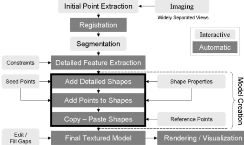
Many reported projects [e.g. 5] as well as our own experience reported that the most time consuming part of the modelling pipeline (figure 2) is the model creation once the 3D points are measured. Therefore, our effort to increase the automation focus on three components: 1. The detailed modelling of basic shapes, such as blocks, columns, windows and arches,
from a small number of interactively measured seed points.
2. The automatic generation of large number of points on shapes that can be represented by implicit functions such as quadrics.
3. The reuse of modelled shapes in other similar parts of the model or another model.
Figure 2: Our 3D image-based modelling pipeline - dark-gray boxes indicate automatic steps.
Those three steps, highlighted by a black box in figure 2, form the nucleus of our 3D modelling procedure. We will describe each in detail in the following sections.
3.1. Semi-Automatic Modelling of Basic Shapes
The general rule for adding points on structural elements and for generating points in occluded or symmetrical parts is to find the new points in 3D space then project them on the images using the known camera parameters. A column is automatically constructed after its direction, radius, and position have been automatically determined from four seed points, two on the corner of the top crown and two on the corners of its base. The ratio between the upper and the lower circle can be set in advance. It is set to less than 1.0 (0.846 or 11/13 in classic architectures) to create a tapered column. From this information, points on the top and bottom circle of the column can be automatically generated in 3D resulting in a complete model. For windows and doors we need four corner points and one point on the window or door surface. By fitting a plane to the corner points, and a plane parallel to it at the surface point, the complete window or door is created. Reconstructing arches starts by fitting a plane to seed points on the front wall. An edge detector is applied to the region and points at constant
interval along the arch are automatically sampled. Using image coordinates of these points (in one image), the known image parameters, and the equation of the plane, the 3D coordinates are computed and projected on the images. Details of the approach are given in [4].
3.2. Automatic Point Generation
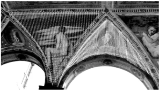
We developed a tool to add points automatically to surfaces of known shapes. It first sets up the boundary of the image region and add points within that region with any desired density. Here, we describe a specially developed procedure aimed at automatically adding large numbers of 3D points to surfaces of basic shapes that can be represented by an algebraic implicit function: F(X, Y, Z) = 0, such as groin-vaulted ceiling. A number of seed points (at least 9 in case of quadric or cylindrical surface) are measured manually in multiple images on each section (figure 3). A quadric, given by:
Ax2 + By2 + Cz2 + 2Dxy + 2Exz + 2Fyz + 2Gx + 2Hy + 2Iz + 1 = 0
is fitted to the seed points in each section (figure 3). The section can be either rectangular or triangular in boundary. Using the parameters of the quadric and the known camera internal and external parameters for a given image, any number of 3D points can be added automatically within the boundary of the section (figure 4). In order to achieve smooth surface model, we may need to generate hundreds of thousands of points per shape. Therefore, efficient modelling software such as PolyWorks [http://www.innovmetric.com] is needed to create the triangular mesh (figure 5). The same software is also used to fill in the gaps between surface elements where no points are generated, as in the case of ceiling panels shown in figure 6. Filling gaps is usually done by either extending and intersecting the two adjacent surfaces, or importing the coordinates of the edge between the two surfaces, if available, then re-meshing (figure 6).
Figure 3: Seed points for ceiling sections. Figure 4: Automatically generated 3D points.
Figure 6: Adding missing parts between arch and ceiling
3.3. Copying and Pasting of Reusable Components
In the previous two steps (sections 3.1 and 3.2), elements of the model can be semi-automatically created at high levels of detail. When the element is to be repeated in other location, we select at least 3 common points with the similar component in another location in an image, then copy and paste the component to the other location. The transformation may include different scales in X, Y, and Z to make up for size change, in which case 5 to 7 common points are measured. The triangular mesh is automatically adjusted to account for the new inserted component. This automatic re-meshing takes into consideration the type of component being pasted. The procedure can be very different from one type of component to another. For example the re-meshing process for a window or a door must create a hole where this component must fit perfectly (figure 7). By contrast, a column can be simply attached to the base model. The texture is replaced with the actual texture of the new location by computing the texture coordinates from the newly pasted 3D points. Figure 8 summarizes this process. The components can be connected with drag-and-drop using simple mouse clicks. Each component is reusable for other projects as well using an import function. Our approach also provides error checks throughout the process. The quality of the pasting process is measured by the residuals of the least-squares adjustment used to find the transformation between reference points on the original components model and the final location. The accuracy may also be checked visually since new vertices are projected on all relevant images.
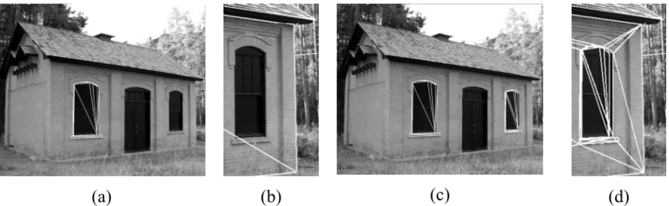
(a) (b) (c) (d)
Figure 7: (a) Left window modelled and copied to file; (b) right window before paste; (c) model pasted on right window (d) Integration of the pasted window model with basic model.
Figure 8: The process of model creation from reusable elements.
4. Experimental Results
This section presents several applications of component building and the copy-paste technique, along with an analysis of its efficiency in producing highly detailed models with less effort than was previously possible.
4.1. The Church in the Old fortress, Corfu City, Greece
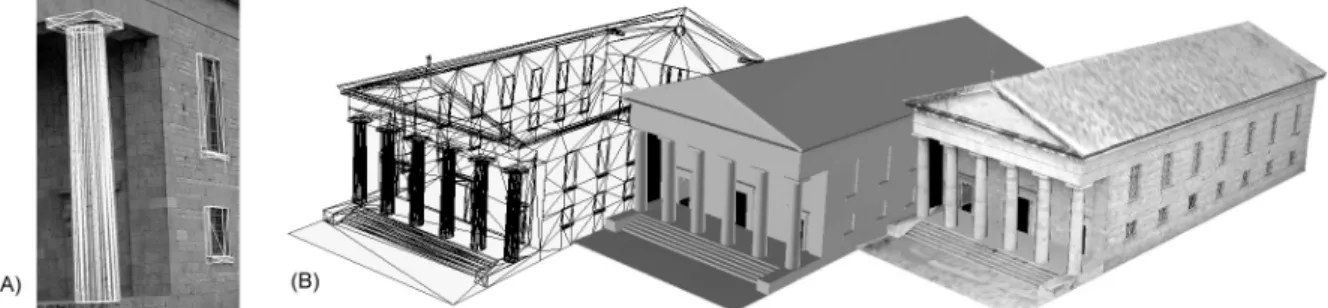
The Greek Church in figure 9-B has 3 reusable components (Figure 9-A) (one type of column and two window types) that were created interactively. From those, 35 components were created automatically [about a factor of 11 improvement]. To create the model, we used only 10 images taken all around the structure, including one from a neighbouring hilltop.
Figure 9: (A) Reusable components, (B) Church model of in wire frame, shaded, and textured.
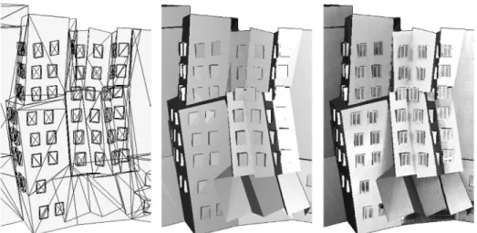
4.2. The Stata Centre, MIT Campus, Cambridge, USA
Another instructive example is the architecturally unique Stata Centre located at MIT campus. The main walls are mostly planes at different angles from each other while the windows are vertical blocks attached to those planes (figure 10). Only one window is constructed interactively in details (figure 11), then copied and pasted to other locations (about 50 in the shown part of the model alone, thus a factor of 50 improvement). This was also helpful because many windows were only partially visible due to the angles of the main surfaces of the building (see figure 1-A above). The shown part was modeled from 6 images.
Figure 10: Stata Centre (MIT) in wireframe, shaded, and textured model.
Figure 11: Model of one window.
4.3. The Romanino Loggia, Trento, Italy
The copy and paste approach was used to model many parts of the Romanino loggia at Buonconsiglio castle in Trento, Italy. Figure 12 shows walls, doors and columns, without the ceiling. The size of the room [21.75 m x 7.80 m x 6.75 m (H)] required a total of 61 images (34 images for the walls and 27 images for the ceiling) at 8-mpixel each. The groin-vaulted ceiling of the loggia has four reusable panels, created interactively, from which 23 were created automatically [a factor of 6 improvement]. Each panel type required only 9 to 12 points to be measured interactively (figure 3) and about 8000 points generated automatically. We used 5-7 well distributed points per panel for the copy and pasting process to compute all the transformation parameters including three scales in X, Y, and Z directions (figure 13).
(a) (b) (c)
(a) (b) Figure 13: (a) One ceiling panel modeled in detail; (b) Panel model pasted on a similar panel.
5. Conclusions
We presented a new technique in the continuing effort to increase the level of automation of image-based 3D modelling. Since in many architectural applications, the structures being modelled contain many repetitive components, the technique can potentially decrease the amount of interactivity by orders of magnitudes, ranging from 6 to 50 times improvement. Our technique has two main contributions: 1) Instead of using predefined generic components such as in CAD-generated libraries, we create a custom library of parts specific to each project. We clone elements derived directly from the image information, 2) we automatically find the relative transformations between the original components and the copied location, and use the actual textures from the new location. Therefore, the resulting model will have higher accuracy and realism than other techniques.
In spite of this effort to increase the level of automation, 3D modelling from images still requires a significant amount of manual interaction. Future work is needed to continue to develop tools that increase the automation further, or at least make the interaction with the modeller much easier. Also, more information is required, for example a quality report, in order to evaluate the possibilities of reusing a given model component for other models or modelling applications. A tool to search the 3D model components database will also be beneficial. Eventually one can envision a system where a less trained user may only create the basic shapes, usually the object main planes, then assemble the details from similar components previously created and archived in a library by those with more expertise.
Acknowledgments:
Stefano Girardi and Francesca Voltolini of ITC-irst performed most of the modelling work for the Romanino loggia experiment, while the “Castello del Buonconsiglio” gave us unrestricted access to the loggia during non-visiting hours. Gary Robertson of ShapeQuest Inc. took the images of the church in the old fortress of Corfu City.
References:
[1] Debevec, P., C.J. Taylor, J. Malik.: Modelling and rendering architecture from photographs: A hybrid geometry and image-based approach. SIGGRAPH’96, pp. 11– 20, 1996.
[2] Dick, A.R., Torr, P.H., Ruffle, S.J., Cipolla, R.: Combining single view recognition and multiple view stereo for architectural scenes, Proc. 8th IEEE International Conference on Computer Vision (ICCV'01), pp. 268-274, 2001.
[3] Dikaiakou, M., Efthymiou, A., Chrysanthou, Y.: Modelling the walled city of Nicosia, 4th Int. Symposium on Virtual Reality, Archaeology and Intelligent Cultural Heritage (VAST), Brighton, UK, pp. 56-65, 2003.
[4] El-Hakim, S.F.: Semi-automatic 3D reconstruction of occluded and unmarked surfaces from widely separated views. Proc. ISPSRS Comm. V Symposium, Corfu, Greece, pp. 143-148, 2002.
[5] Kersten, T., Pardo, C.A., Lindstaedt, M.: 3D acquisition modelling and visualization of north German castles by digital architectural Photogrammetry, Proc. ISPRS XXth Congress, Istanbul, 2004.
[6] Koshak, N, Gross, M.D.: 3D Modelling of historic Makkah, CAADRIA '98: 3rd Conf. on Computer Aided Architectural Design Research in Asia, Osaka, Japan, 1998.
[7] Lee, S.C., Nevatia, R.: Interactive 3D Building Modelling Using a Hierarchical Representation, IEEE Workshop on Higher-Level Knowledge in 3D Modelling and Motion (HLK) part of ICCV’03, Nice, October, pp. 58-65, 2003.
[8] Liebowitz, D., A. Criminisi, A. Zisserman, A.: Creating Architectural Models from Images, EUROGRAPHICS ’99, 18(3), 1999.
[9] Nassar, K., Thabet, W., Beliveau, Y.: Building assembly detailing using constraint-based modeling, Automation in Construction, 12, pp. 365-379, 2003.
[10] Pollefeys, M., Koch, R., Van Gool, L.: Self-calibration and metric reconstruction in spite of varying and unknown intrinsic camera parameters. Int. J. of Computer Vision, 32(1), pp. 7-25, 1999.
[11] Schindler, K., Bauer, J.: A model-based method for building reconstruction. Proc. ICCV workshop on Higher-Level Knowledge in 3D Modelling and Motion (HLK'03), 2003. [12] Werner, T., Zisserman, A.: New technique for automated architectural reconstruction