Development of a Passive and Slope Adaptable Prosthetic Foot
The MIT Faculty has made this article openly available.
Please share
how this access benefits you. Your story matters.
Citation
Amiot, David E., Rachel M. Schmidt, Angwei Law, Erich P. Meinig,
Lynn Yu, Kathryn M. Olesnavage, Victor Prost, and Amos G. Winter.
“Development of a Passive and Slope Adaptable Prosthetic Foot.”
Volume 5A: 41st Mechanisms and Robotics Conference (August 6,
2017).
As Published
http://dx.doi.org/10.1115/DETC2017-67947
Publisher
ASME International
Version
Final published version
Citable link
http://hdl.handle.net/1721.1/120789
Terms of Use
Article is made available in accordance with the publisher's
policy and may be subject to US copyright law. Please refer to the
publisher's site for terms of use.
DEVELOPMENT OF A PASSIVE AND SLOPE ADAPTABLE PROSTHETIC FOOT
ABSTRACT
Historically, users of prosthetic ankles have relied on actively operated systems to provide effective slope adaptability. However, there are many drawbacks to these systems. This research builds upon work previously completed by Hansen et al. as it develops a passive, hydraulically operated prosthetic ankle with the capability of adapting to varying terrain in every step. Using gait cycle data and an analysis of ground reaction forces, the team determined that weight activation was the most effective way to activate the hydraulic circuit. Evaluations of the system pressure and energy showed that although the spring damper system results in a loss of 9J of energy to the user, the footplate stores 34J more than a standard prosthesis. Therefore, the hydraulic prosthetic provides a 54% increase in stored energy when compared to a standard prosthesis. The hydraulic circuit manifold prototype was manufactured and tested. Through proof of concept testing, the prototype proved to be slope adaptable by successfully achieving a plantarflexion angle of 16 degrees greater than a standard prosthetic foot currently available on the market.
BACKGROUND & INTRODUCTION
In the United States, approximately 378,000 individuals have a transtibial amputation [1]. Commercially available passive (no
microprocessor) prosthetic foot-ankle systems generate effective foot-ankle function by relying on spring flexion or rotational movement about one static equilibrium point. These prostheses are suitable for walking on level ground but problems often arise when users attempt to walk on uneven or sloped terrain [2]. Able-bodied persons are able to carry out the necessary ankle alignment adjustments for safe, stable ambulation on sloped terrain, but amputees often have to adjust their gait pattern to compensate for the deficiencies of the prosthesis, often by relying heavily on their non-affected limb, increasing energy expenditure and socket discomfort [3]. Failure to adapt to sloped terrain can lead to increased peak loading in the socket and tissue damage on the residual limb [4]. The motivation behind this work was to improve quality of life for individuals using prosthetic feet by developing a slope adaptable prosthetic foot-ankle system that would not require motors or batteries (i.e., passive).
Existing Devices and Limitations
Current prostheses on the market that allow for ankle motion and adjustment to uneven terrain can be divided into two primary categories: microprocessor-controlled and passive hydraulic damping devices. Microprocessor-controlled prosthetic feet include Ossur’s Proprio Foot [5] and Endolite’s Elan foot [6], among others. These actively operated devices David E. Amiot, Rachel M. Schmidt, and Angwei Law
Sloan School of Management School of Engineering
Massachusetts Institute of Technology Cambridge, MA 02139
Erich P. Meinig, Lynn Yu, Kathryn M. Olesnavage, and Victor Prost
Department of Mechanical Engineering Massachusetts Institute of Technology
Cambridge, MA 02139 Amos G. Winter, V
Global Engineering and Research Laboratory Department of Mechanical Engineering
Massachusetts Institute of Technology Cambridge, MA 02139
Proceedings of the ASME 2017 International Design Engineering Technical Conferences and Computers and Information in Engineering Conference IDETC/CIE 2017 August 6-9, 2017, Cleveland, Ohio, USA
are capable of controlling the dorsiflexion (lifting the toes upward) and plantarflexion (pushing the toes downward) of the prosthesis. However, they do not independently adapt to each unique step; instead, the foot adjusts incrementally and is unsuitable for rapidly changing terrain. Additionally, these feet are not passively operated, meaning they are large, heavy, and require recharging the battery. The recently-released Meridium foot by Ottobock claims to adjust “immediately to the user’s walking conditions, whether on slopes, stairs, or varying terrain” [7]. However, this claim has not yet been investigated in the literature.
Passively hydraulically operated prosthetic feet include the Echelon foot (by Endolite) [8] and the MotionFoot (by Motion Control Inc.) [9] among others. These feet incorporate a hydraulic component to passively control the rates of dorsiflexion and plantarflexion of the foot. However, the use of dampers takes energy out of the system, which may increase the metabolic cost to the users. Additionally, dampers often have physical stops at the end of the range of motion (sometimes permitting as little as 3 degrees of motion from a neutral angle) of the prosthesis, consequently causing the ankle to rotate at a fixed equilibrium point [10]. As a result, these feet are not slope adaptable. The prosthetic foot-ankle system developed through this research works to combat this energy loss and provide a biomimetic range of motion to improve the slope adaptable functionality.
It is desirable to have a prosthesis that sets the equilibrium point independently for each step based on the slope of the surface encountered, much like the Mauch ankle did [11]. Designed by Hans Mauch in the late 1950’s, this prosthetic ankle was designed to improve quality of life for individuals living with amputations by providing slope adaptability. The Mauch ankle utilized a ball in a track that closed a port in the hydraulic circuit therefore effectively locking the ankle when the shank reached vertical. However, it suffered from leakage and the need for frequent maintenance [10, 11]. Further improvements based on the Mauch Ankle by Hansen et al. solved the leaking issues by replacing the rotary hydraulic with a linear hydraulic and incorporated a footplate as a cantilever to offset the energy loss from dampeners during rollover. However, this improved ankle utilized a tilt-sensor to activate the cutoff valve to lock the ankle making it an actively operated prosthesis rather than a passive prosthesis [12].
Our goal for the present work was to refine the design by Hansen et al. by incorporating a mechanically activated cutoff valve to replace the microprocessor controlled valve in the hydraulic circuit.
Gait Cycle Mechanics and Analysis
To gain a better understanding of the parameters involved in designing a passive, slope-adaptable prosthetic foot, the team analyzed a typical gait cycle. There are two primary phases:
swing phase and stance phase. During swing phase, the foot is moving in the air; during stance phase, the foot comes into contact with the ground and goes through several sub-phases (see Figure 1 for the sub-phases and forces acting during stance phase). The first sub-phase is heel strike, which is the moment when the heel first comes into contact with the ground. A ground reaction force (GRF) acts at the heel, and can be broken down into its horizontal and vertical ground reaction forces (GRFx and GRFy). At this stage, GRFx is acting from the
front of the foot toward the back to decelerate the foot. The second sub-phase is foot flat, when the foot undergoes plantarflexion until it is completely flat on the ground. Once the foot is flat, the shank rotates towards the front of the foot, resulting in dorsiflexion. Throughout this process, the center of pressure of the foot moves from the heel towards the toe, thus shifting the location of the GRF. Additionally, GRFx becomes
approximately zero when the shank is vertical. As the shank continues to rotate forward, the direction of GRFx changes to
the forward direction, acting to propel the knee forward over the foot. The final sub-phase is terminal stance, where the foot plantarflexes and the heel lifts off, such that only the toes remain in contact with the ground. At the end of terminal stance, the toes break contact with the ground in an event called toe-off. After toe off, the foot is completely lifted off the ground and swings forward in the air, moving on to the next cycle.
FIGURE 1: GAIT CYCLE MECHANICS
To explore different ways of passively actuating the slope adaptability of the prosthetic foot, gait cycle data were analyzed to study the feasibility of using various measurable characteristics such as GRF, ankle moment, ankle flexion angle, and foot center of pressure. The team used empirical data from Winter, which was collected from a 56.7kg able-bodied test subject [13]. The data were normalized so that they could be applied to subjects of different body weights and sizes. After evaluating Winter’s data [13], the team determined that the GRF aligned well with the timing for activating and deactivating slope adaptability.
The GRF is split into its horizontal and vertical components (see Figure 2) over a gait cycle. The vertical component (Y) is much larger in magnitude than the horizontal component (X)
and is always positive (i.e., in the same direction). This makes it a suitable candidate for activating the slope adaptability of the prosthetic foot. The vertical component also shows two sharp peaks – one right after heel strike and one just before toe off. These peaks coincide well with the moment when slope adaptability should be activated and deactivated.
FIGURE 2: NORMALIZED GRF.
PROTOTYPE DESIGN & ANALYSIS High Level Design Concept
Slope adaptability is critical to improving quality of life for individuals living with amputations, as it provides them additional lifestyle flexibility and opportunities, and decreases pressure and potential injury on the body. This led the team to develop the concept of utilizing the force from the user’s weight through the shank to activate a cutoff valve in a hydraulic circuit, enabling slope adaptability in the foot. The team investigated different means to use the weight to activate a cutoff valve, including systems employing gears and magnets. Following a preliminary literature review and design analysis of these alternatives, the team determined that a push-button style activation would provide a viable solution.
Hydraulic Circuit Actuation
The basis of this design was provided to the team by Hansen et al., with the directive to determine the optimum activation strategy. The hydraulic circuit and its function during a gait cycle are shown in Figure 3. The circuit consists of a hydraulic cylinder with a piston and spring, a check valve and a cutoff valve connected in parallel, as shown in Figure 3A. The cutoff valve can be activated and deactivated by an external input to either cut off or allow fluid flow. In this case, the cutoff valve is activated by the user’s weight (specifically the GRFs and resulting ankle reaction forces).
Figure 3B shows the positioning of the circuit in relation to the movement of the prosthesis through the gait cycle. When the heel strikes the ground (step 1), the piston is compressed by the weight of the user. Fluid is allowed to flow through the check
valve (green arrows showing direction of flow), and this allows the foot to plantarflex to find the ground. At the same time, the cutoff valve is activated by the ankle reaction force, meaning the fluid cannot flow from the top of the chamber to the bottom, thus preventing dorsiflexion. Once the foot is flat on the ground (step 2), the shank will attempt to rotate forward and dorsiflex, but the cutoff valve remains activated as there is still a force acting on it. As a result, the ankle joint angle (θ) remains constant. Instead of ankle dorsiflexion, the footplate starts to bend to allow the shank to move forward (step 3). This bending allows the footplate to store energy, to aid in lifting the foot off the ground after toe off (step 4). At toe off, the weight is lifted off the cutoff valve, allowing it to open for the flow of fluid through it (yellow arrows showing direction of flow). This allows the piston to extend, allowing for dorsiflexion to occur. The spring connected to the piston releases its stored energy at this point,helping the foot to dorsiflex and return to its neutral position in swing phase. Overall, the hydraulic circuit allows the foot to adapt to varying slopes by varying the amount of piston compression.
(A)
(B)
FIGURE 3: INCLUDES (A) DIAGRAM OF THE HYDRAULIC CIRCUIT AND (B) GAIT CYCLE STAGES SHOWING THE HYDRAULIC CIRCUIT ACTUATION [14].
2.76 Global Engineering: Putting MIT’s Best Foot Forward Check Valve Hydraulic
Analysis of Pressure in the Hydraulic Circuit
The objective of the pressure analysis was to determine the maximum pressures that occurs within the hydraulic circuit. This information is critical to identifying the appropriate components to construct the circuit, which ensures proper function and longevity of the system for the user.
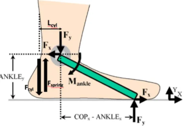
This analysis begins with the moments that occur around the center of the ankle. The human ankle’s muscles, tendons, and ligaments work together to create a moment to balance the moment generated by the ground reaction forces. Figure 4 details the forces acting on the prosthetic ankle and the resulting moments [2].
FIGURE 4: FORCES ACTING ON THE ANKLE.
With this analysis and the GRF, ankle angle, and ankle location data evaluated previously, it is possible to calculate the moment the hydraulic cylinder must generate to balance the moments generated by the spring and the ground reaction forces. Equation 1 is the result of this moment analysis.
𝐹"#$%&'()=+,-./012+345,72+345,8
9:8;/0<=. (1)
Equation 2 gives the resulting pressure generated by this force. 𝑃"#$%&'()=
?:8;/0<=.
@:8;/0<=. (2)
Knowing the pressure in the hydraulic cylinder allows for calculation of the pressure inside the remaining circuit. The cutoff and check valves that control the flow of the hydraulic fluid experience a pressure that depends on both the pressure in the hydraulic cylinder and the geometry of the tubing that connects the valves to the piston. Applying the principle of conservation of energy, it is possible to determine the pressure in the hydraulic piping, as given by Equation 3.
𝑃A%B(= 𝑃"#$%&'()+ DE-/FGH0I J − DE-/-=I J − DL9E-/-=I JM-/-= (3)
Completing the analysis described above generated values for the maximum allowable pressure in the hydraulic cylinder (792 psi) and in the piping system (791 psi).
These results are the foundation of the initial hydraulic system design.
Analysis of Energy Requirements to Activate the Hydraulic Circuit
The second primary element of the hydraulic circuit design is the energy stored by the system and the energy required to reset the ankle during the swing phase. The addition of the hydraulic cylinder to the prosthetic ankle adds damping and energy loss to the system. It is critical to design this system in a manner such that the damping of the hydraulic system does not prevent the user from activating the locking mechanism through the application of weight onto the ankle.
The key factors in the energy analysis are as follows:
• Time available between heel strike and foot flat to lock the ankle
• Time available during swing phase to reset the ankle, and the energy stored by the foot plate
• Maximum allowable damping coefficient that will allow the foot to lock and reset during the gait cycle
• Minimum spring coefficient required to reset the ankle during swing phase
Time Analysis
The first step in the energy analysis is to determine the time available to allow the foot to “find the surface” between heel strike and foot flat and the time available to reset the ankle while the foot is in swing phase. These times establish the conditions that will dictate the maximum allowable damping coefficient and the minimum requirement for the spring constant. If the damping coefficient is too high, the user’s weight will not be sufficient to achieve foot flat during the available time period. If the spring constant is too low, the ankle will not be able to reset in the early swing phase for toe clearance and the ankle will not be prepared for the user’s next step. An analysis of the experimental gait cycle data indicates that foot flat occurs approximately 0.086 seconds after heel strike, see Figure 5.
FIGURE 5: ANALYSIS OF TIME BETWEEN HEEL STRIKE AND FOOT FLAT.
Spring Damper System Analysis
Due to the previously discussed time analysis, the dynamics of the system were tuned such that the foot achieves foot flat fast enough for a typical gait cycle and returns to neutral during a standard swing phase. As a result of this design, it is possible to analyze the hydraulic ankle as a spring damper system. Much like the time analysis, there are two distinct scenarios in which the spring damper system can be analyzed. The first scenario is the heel strike to foot flat phase. In this scenario, the user applies a force to the system by transferring weight onto the foot (Figure 6).
FIGURE 6: SPRING DAMPER SYSTEM DURING THE HEEL STRIKE TO FOOT FLAT PHASE.
Under these conditions, the spring-damper system can be modeled with Equation 4 where b is the damping coefficient, k is the spring constant, and x is the distance travelled.
𝐹 𝑡 = 𝛽𝑥 + 𝑘𝑥 (4)
The second scenario occurs when the foot is in swing phase. During this time, the user does not apply a force to the spring damper system. In this scenario, the spring-damper system can be modelled by Equation 5.
𝛽𝑥 + 𝑘𝑥 = 0 (5)
The final element of the spring damper system is to consider the range of motion the system will experience as the spring compresses and the circuit locks. The geometry of the ankle design creates a moment arm (r) between the location of the force application into the system and the linkage to the spring-damper system. In addition, experimental results compiled by Hansen et al. indicate that the existing actively operated slope adaptable foot allows for 16 degrees of plantar flexion (angle q) as the foot plate finds the ground after heel strike [2]. This degree of plantar flexion, combined with the moment arm of the spring-damper system linkage, allows for the calculation of distance the spring compresses after heel strike.
Given these known dimensions and the previously discussed time value associated with the system activation, it is possible to solve for the dampingcoefficient and the spring constant by solving the above equations as a system of equations. Doing so yields a minimum spring constant value of 4352 N/m and a maximum damping coefficient of 1391 kg/s. These values establish the design requirements that must be fulfilled by the design of the hydraulic circuit, spring selection, and hydraulic fluid selection.
Footplate Analysis
The next step in the energy analysis considers the footplate as a cantilever beam in bending that stores and returns energy in the same manner as a spring. The analysis centers on a comparison between a traditional prosthetic ankle and one with a hydraulic circuit that allows for a greater angular deflection by allowing the foot to plantar flex until it locates the ground and then locks to prevent dorsiflexion.
A traditional prosthetic ankle maintains a 90-degree angle through the gait cycle and data from Hansen et al. indicates that the footplate deflects approximately 32 degrees during the gait cycle [2]. This deflection was calculated by assuming a beam in bending.
This analysis indicates that a standard prosthetic ankle with a typical foot plate material stores approximately 45 J during the gait cycle. Equation 6 describes the energy stored in the foot plate as part of a traditional fixed ankle system.
𝐸 =T
J𝑘𝛼
J (6)
The addition of a hydraulic circuit allows for an additional 16 degrees of bending due to the increased plantar flexion as the foot finds the ground following heel strike, which equates to greater energy storage. The new angle through which the beam bends is now the original angle, a, plus the additional angle 0.0 100.0 200.0 300.0 400.0 500.0 600.0 700.0 0.000 0.100 0.200 0.300 0.400 0.500 0.600 0.700 GR F (y ) ( N ) Time (s) Ground Reaction Force (y) vs Time Foot flat: 0.086 s
allowed by the hydraulic system, apiston, as shown in Equation
7. 𝐸 =T
J𝑘(𝛼 + 𝛼B%WXY&)
J (7)
This additional 16 degrees of plantarflexion allows the foot plate to store an additional 34 J of energy. This additional stored energy can be returned to the user during the gait cycle, indicating that this hydraulic system not only provides slope adaptability, but also improved energy storage and return. Initial Prototype
The preliminary prototype was built as a system of discrete components including piping, fittings, the valves. A cutoff valve manufactured by Clippard with a push button activation system that met design specifications was identified. By locating the push button valve underneath the shank, the user’s weight could directly activate the cutoff valve in the hydraulic circuit.
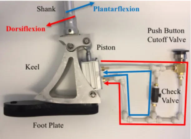
To verify the feasibility of using a push button valve to activate a hydraulic circuit, an enlarged version of the circuit was built and affixed to the prosthetic foot prototype designed by John Skelton, sent to us by Hansen et al., see Figure 7. The red arrow shows the flow of hydraulic oil through the system during dorsiflexion. The flow is impeded when the push button cutoff valve is activated.
FIGURE 7: PRELIMINARY HYDRAULIC PROTOTYPE.
The system uses a check valve and push button cutoff valve to control the piston, and thus the movement of foot relative to the shank. The check valve only allows for one-way flow, or plantarflexion. The cutoff valve, in its normal state, allows for flow in both directions in the circuit, enabling dorsiflexion and plantarflexion. When the button is pushed, the cutoff valve prevents flow in either direction. In the final design, the push button valve is located underneath the shank, and activated by the user’s weight.
In the gait cycle, when the user strikes their heel against the ground, the push button valve is activated. Flow is shut off in the dorsiflexion direction, ensuring the ankle is stiff as the foot rolls over across the ground. However, the check valve enables plantarflexion, allowing the foot to adjust to the slope of the ground as it rolls over.
Upon toe-off, the user’s weight is shifted to the other foot, releasing the push button cutoff valve. With the aid of a spring under the hinge (not included in the prototype shown in Figure 7), the foot is restored to a resting position.
This bench top prototype is not practicable as a final design, due to the lack of an accumulator, the improper placement of the push button valve, and the large size. However, it demonstrated the feasibility of the hydraulic circuit in controlling the movement of the foot and shank. Next, the team worked on the integration of this circuit with the rest of the foot in a compact, secure manner. The three potential solutions investigated were a rotary hydraulic system, a manifold design, and a smaller scale pipe and valve system. Ultimately, the team went forward with the manifold design due to the relative ease of manufacturing and its ability to withstand the high pressures in the system (>800 psi).
Final Prototype Design and Fabrication
The design of the hydraulic circuit is based upon the pressure and energy evaluation above. The spring previously used by Hansen et al in an actively operated hydraulic ankle was selected as it provided significant stiffness at 25,000 N/m. This spring also met the energy and pressure requirements discussed previously. Maintaining consistency between the Hansen et al components was deemed useful as it provides a means to compare the active and passive models.
It was also necessary to select a hydraulic fluid based upon the maximum allowed damping coefficient for the system. The Hagen-Poiseuille equation describes the relationship between the change in pressure and the dynamic viscosity of a fluid (Equation 8):
∆𝑃 =\]9@_)-/FGH0` ^ (8) It is possible to solve for the force acting on the hydraulic piston based on the piston’s area, and rearranging Equation 8 provides the following relationships (Equations 9, 10, 11) exerted on the piston by the fluid and the dynamic viscosity of the fluid:
𝐹 = ∆𝑃𝐴B%WXY& (9)
𝐹 = 𝛽𝑣 (10)
𝛽 =]9@-/FGH0I ^
_)` (11)
Selecting mineral oil with a viscosity of 0.00618 Pa×s yields a damping coefficient of 415 kg/s, which meets the requirement determined previously that the damping coefficient must be below 1391 kg/s. The 415 kg/s damping coefficient was deemed acceptable because the team decided to mineral oil as recommended by Hansen et al. Consistency between hydraulic fluid allows for comparison between models and prototypes. To show that the hydraulic cylinder creates a damping system for the piston, the team needed to prove that there is laminar flow in the piston cylinder. The damping mainly occurs in the cylinder containing the piston, noted as the “hydraulic cylinder and piston” in Figure 9. The team disregarded the other parts of the hydraulic circuit, including the interior pipes of the manifold and the tubing connecting the piston cylinder to the manifold.
Next, the team calculated the Reynolds number to determine if the flow is laminar or turbulent, see Equation 12. The density and absolute viscosity of the mineral oil are known. The diameter of the cylinder model is 0.025 meters. The velocity is determined based on data from Winter [13] on the speed of the cylinder during the gait cycle. Using these values, the Reynolds number was determined to be 623 (dimensionless number), which is less than 2000, classifying the flow in the piston as laminar.
𝑅𝑒 =D∗E∗'] = 623 (12) To verify our model’s assumption that the piston acts as a hydraulic damper, the team decided to determine if the flow is fully developed in the cylinder. However, the flow is in fact not fully developed as a result of the length of the cylinder being far smaller than the minimum entrance length for fully developed laminar flow, as shown in Equation 13.
𝐿𝑒 = 0.06 ∗ 𝑅𝑒 ∗ 𝑑 = 0.9345 𝑚 (13) Because the flow is not fully developed, the damping experienced by the real system will be higher. We believe our model is still useful as a first order approximation of the hydraulic system, and we selected mineral oil as the hydraulic fluid because it provides a conservative damping coefficient for the system. The mineral oil provides a damping coefficient that is significantly less than the maximum constraint previously calculated (415 kg/s to meet a maximum constraint of 1391 kg/s).
The manifold was machined from aluminum and a Clippard switch-activated valve placed into the manifold to create the cut-off valve. The one-way check valve was constructed of a
pin with a neoprene ball of 3/16-inch diameter. This rubber ball is seated above a restriction in the pipe diameter; when fluid flows up through the pipe, the ball is lifted away from the diameter restriction, allowing fluid to flow. Fluid attempting to flow the other way is blocked by the ball as it rests against the diameter restriction and obstructs flow. Figure 8 details the design of the manifold and arrangement of the valves in the system.
FIGURE 8: HYDRAULIC CIRCUIT MANIFOLD DESIGN.
The final prototype (see Figure 9) utilized the footplate, piston, and shank attachment piece from John Skelton’s model. The keel was redesigned, and split into the rocker piece and the upper keel, housing the manifold in between. Both pieces were machined out of aluminum using a water jet and mill. A cutout was created in the rocker to reduce its weight. The manifold was affixed to the rocker using bolts through the back of the rocker and through the footplate. Part of the accumulator piece from Skelton’s was affixed to the front of the manifold.
FIGURE 9: FINAL PROTOTYPE RENDERING.
The switch-activated cutoff valve allows the user to apply weight to the ankle and prevent the hydraulic cylinder from extending. This valve is normally opened, meaning that if the switch is not depressed, the valve is open and fluid can flow. When the user applies weight to the ankle at heel strike, this force is transferred through the pylon and pyramid to the ankle through the upper rocker. This rocker rests on a spring and slides vertically on two shoulder bolts that constrain the upper rocker’s motion (see Figure 10). When the user applies weight
to the ankle, the upper rocker moves downward on the shoulder bolts and depresses the switch, thereby closing the cutoff valve. Closing this valve prevents dorsiflexion but allows the ankle to plantar flex due to the one-way check valve. This plantarflexion allows the footplate to find the walking surface.
FIGURE 10: COMPLETED HYDRAULIC FOOT.
RESULTS & DISCUSSION
The system was filled with hydraulic fluid upon completing fabrication. Air was bled from the system through an iterative process. The system was checked for leaks and left over night to allow for slow leaks to become apparent. Once leaks were resolved, the team conducted proof of concept testing.
Proof of Concept Testing
The two primary objectives of the prosthetic foot were passive operation and slope adaptability. By achieving these two objectives, the current state of the art foot could be improved upon using this type of hydraulic circuit to improve the quality of life for individuals living with amputations. Due to the design and construction of the foot, the prototype is passive. To test the slope adaptability, the team considered testing several variables, including incline, walking speed, load, and surface type. After discussions with partners, it was determined that incline was the only critical variable to proving the concept.
The team conducted testing on three inclines: sixteen degrees uphill, sixteen degrees downhill, and level ground. Sixteen degrees was identified as the testing angle because that was the estimated improvement that the hydraulic ankle could expect to achieve over a standard prosthetic, as presented in the energy calculations above. To conduct effective testing, the team worked with Hansen et al. and reviewed Skelton’s Thesis to develop a methodology that would remove the variation in angles recorded when the foot first achieves heel strike.
The trials on each incline were completed ten times. Upon heel strike, the team measured the angle between the shank and the footplate with a digital angle finder. After plantarflexion, the team again measured the angle between the shank and the footplate. The difference in these two values provided the plantarflexion angle. Figure 11 presents the data collected through the testing, including the averages, and 95% confidence intervals, where sample size n = 10.
FIGURE 11: PROOF OF CONCEPT TEST RESULTS.
These data show that the prosthesis achieved an average of 17.2 degrees, 15.9 degrees, and 16.3 degrees for uphill, downhill, and level ground inclines, respectively. The team believes this proves the hydraulic circuit concept, in that each the foot can reach approximately 16 degrees on each incline. This means the hydraulically operated foot can achieve on average 16 degrees more plantarflexion than the standard prosthetic foot. This provides significantly increased slope adaptability, which will therefore increase flexibility and expand lifestyle opportunities for individuals living with prosthetics.
The team confirmed this data by conducting a strategic evaluation of the hydraulic foot at four critical locations in the gait cycle: heel strike, foot flat, toe off, and swing phase. During this strategic evaluation, the team measured the angles between the shank and footplate, similar to above. The team also measured the time it took to reset the ankle after toe off, during swing phase. As mentioned previously, this timing is critical because if the ankle does not reset prior to heel strike, the user will not gain the full benefit of the hydraulic foot. In measuring this time, the team found that the ankle reset nearly immediately after the load was removed, therefore proving that the foot would have ample time to reset prior to heel strike. This test could be improved with more accurate quantitative measurement tools available in a motion lab, with the ability to apply a designated load, take rapid photos, and include motion sensors to measure data.
Limitations: the team identified several limitations to the design and the testing methodology, including the following:
Upper rocker Location of
Design: the team used several components provided by Hansen et al. including the primary spring, hydraulic cylinder, and fluid type. Each of these factors played a significant role in how the prosthetic performed. Future work may include testing a prototype with several different springs, cylinders, and fluids, to measure the variation.
Manufacturing: the foot was manufactured primarily from aluminum, which is very heavy. Future work may include evaluating materials of construction that will be strong enough to hold the loads and pressures required, yet light enough to be viable for a user to use effectively. Additionally, manufacturing efficiencies could be explored and implemented to improve manufacturing effectiveness.
System Integration: the shank, ankle hinge, hydraulic cylinder, hydraulic circuit, rocker, and footplate all need to work together to provide maximum benefit. This system could be evaluated and optimized to reduce unneeded energy loss.
Components: the team considered using a shock absorber and a rotary hydraulic system as design options for the ankle. They both provide the opportunity to be compact solutions. Future work may include further evaluation and testing.
CONCLUSION
This passive hydraulic circuit makes it possible for individuals using prostheses to adapt to varying slopes and changing terrain in one step. Current prosthetic feet available on the market that are slope adaptable are actively operated, making them heavy, expensive, and impractical. Available prosthetic feet that are passively operated do not have the functionality required to quickly adapt to changing slopes. This hydraulic circuit will provide the functionality required to operate the foot passively and provide the slope adaptation capabilities. This will provide individuals using the prosthetic foot with increased mobility and stability, therefore improving their quality of life.
The learnings from this work include the proof of concept that hydraulically operated prosthetic systems can be passively activated and the increased energy storage due to the hydraulic circuit operation.
This work proves that passively operated hydraulic systems can be used within a prosthetic foot. Using the individual’s body weight and resulting ground reaction forces, the circuit can be passively activated to engage the system. The locking mechanism activated by the weight allows the user to safely complete a roll-over of the foot before unlocking at toe-off. The spring mechanism that supplements the hydraulic circuit provides the force required to pull the foot back into position prior to the following heel strike.
Additionally, this work proves that more energy can be stored in the footplate, such that the energy consumed by the hydraulic
system does not exceed the surplus energy stored in the footplate. This finding is valuable because it shows that users may be able to use this prosthetic foot regularly (therefore enjoying the improved stability and functionality), without adding the burden of additional energy required per step. This circuit will assist in the development of future hydraulically operated prosthetic feet. These feet will provide users with increased mobility and stability at a low cost of energy dissipation. Overall, this prosthetic foot has the capability of improving quality of life for individuals using prosthetics.
Additional work may include rigorous testing of the system to progress from proof of concept to streamlining the design and developing an applicable prototype for usability testing. Similarly, a more in-depth analysis of the hydraulic system and its representation as a spring-damper system beyond a first order analysis can be conducted to generate greater insight into the dynamics in the system.
ACKNOWLEDGEMENTS
This work was performed for the 2.76 Global Engineering course and was funded by Tata Center for Technology and Design at Massachusetts Institute of Technology. The team would like to thank Andrew Hansen, Eric Nickel, Greg Voss, Bob Hauck and Pooja Mukul for their insight and contributions to the project.
REFERENCES
[1] Ziegler-Graham, K., MacKenzie, E., Ephraim, P., Travison, T., and Brookmeyer, R. "Estimating the Prevalence of Limb Loss in The United States: 2005 To 2050". Archives of Physical Medicine and Rehabilitation 89.3 (2008): pp. 422-429. Web. [2] Williams, R., Hansen, A., and Gard, S. "Prosthetic Ankle-Foot Mechanism Capable of Automatic Adaptation to The Walking Surface". Journal of Biomechanical Engineering 131.3 (2009): p. 035002. Web.
[3] Vrieling, A., Van Keeken, H., Schoppen, T., Otten, E., Halbertsma, J., Hof, A., and Postema, K. "Uphill and Downhill Walking in Unilateral Lower Limb Amputees". Gait & Posture 28.2 (2008): pp. 235-242. Web.
[4] Portnoy, S., Van Haare, J., Geers, R., Kristal, A., Siev-Ner, I., Seelen, H., Oomens, C., and Gefen, A. "Real-Time Subject-Specific Analyses of Dynamic Internal Tissue Loads in The Residual Limb of Transtibial Amputees". Medical Engineering & Physics 32.4 (2010): pp. 312-323. Web.
[5] "Proprio Foot". Ossur.com. 2017. Web. https://www.ossur.com/prosthetic-solutions/products/dynamic-solutions/proprio-foot
[6] "Elan - Carbon, Feet, Hydraulic - Endolite USA - Lower Limb Prosthetics". Endolite USA - Lower Limb Prosthetics. 2017. Web. http://www.endolite.com/products/elan
[7] “Meridium: Reclaim your Way”. Ottobock. 2017. Web.
http://www.ottobock.co.uk/media/local- media/brochures/prosthetics/meridium/meridium-cpo-brochure.pdf
[8] "Echelon - Carbon, Feet, Hydraulic - Endolite USA - Lower Limb Prosthetics". Endolite USA - Lower Limb Prosthetics. 2017. Web. http://www.endolite.com/products/echelon
[9] “Motionfoot MX”. Motion Control, Inc. 2017. Web. http://www.utaharm.com/motionfoot-foot-prosthetic.php
[10] Nickel, E., Sensinger J., and Hansen, A. "Passive Prosthetic Ankle-Foot Mechanism for Automatic Adaptation to Sloped Surfaces". Journal of Rehabilitation Research and Development 51.5 (2014): pp. 803-814. Web.
[11] Sowell, T. “A Preliminary Clinical Evaluation
of the Mauch Hydraulic Foot-Ankle System”. Prosthetics and Orthotics International (1981): pp. 87-91. Web.
[12] Skelton, J. “Development of a Terrain Adapting
Prosthetic Ankle based on the Mauch Ankle”. Master’s Thesis (2016): pp. 1-33. University of Minnesota, Minneapolis, MN. [13] Winter, David A. Biomechanics and Motor Control of Human Movement. 1st ed. New York, N.Y. [etc.]: Wiley, 2009. [14] Modified from graphic provided by A. H. Hansen.