Development of a Cold Gas Propulsion System
for the TALARIS Hopper
by
Sarah L. Nothnagel
B.S. Astronautical Engineering University of Southern California, 2009Submitted to the Department of Aeronautics and Astronautics in Partial Fulfillment of the Requirements for the Degree of
Master of Science in Aeronautics and Astronautics
at the
Massachusetts Institute of Technology
June 2011
© 2011 Massachusetts Institute of Technology. All rights reserved.
Signature of Author: ____________________________________________________________________ Department of Aeronautics and Astronautics
May 16, 2011 Certified by: __________________________________________________________________________
Jeffrey A. Hoffman Professor of the Practice of Aerospace Engineering Thesis Supervisor Certified by: __________________________________________________________________________
Brett J. Streetman Senior Member of the Technical Staff, Draper Laboratory Thesis Supervisor Accepted by: __________________________________________________________________________
Eytan H. Modiano Associate Professor of Aeronautics and Astronautics Chair, Graduate Program Committee
3
Development of a Cold Gas Propulsion System
for the TALARIS Hopper
by
Sarah L. Nothnagel
Submitted to the Department of Aeronautics and Astronautics on May 16, 2011, in Partial Fulfillment of the
Requirements for the Degree of Master of Science in Aeronautics and Astronautics
Abstract
The TALARIS (Terrestrial Artificial Lunar And Reduced gravIty Simulator) hopper is a small prototype flying vehicle developed as an Earth-based testbed for guidance, navigation, and control algorithms that will be used for robotic exploration of lunar and other planetary surfaces. It has two propulsion systems: (1) a system of four electric ducted fans to offset a fraction of Earth’s gravity (e.g. 5/6 for lunar simulations), and (2) a cold gas propulsion system which uses compressed nitrogen propellant to provide impulsive rocket propulsion, flying in an environment dynamically similar to that of the Moon or other target body. This thesis focuses on the second of these propulsion systems. It details the practical development of the cold gas spacecraft emulator (CGSE) system, including initial conception, requirements definition, computer design and analysis methods, and component selection and evaluation. System construction and testing are also covered, as are design modifications resulting from these activities. Details of the system’s integration into the broader TALARIS project are also presented. Finally, ongoing and future work as well as lessons learned from the development of the CGSE are briefly discussed.
Thesis Supervisor: Jeffrey A. Hoffman
Title: Professor of the Practice of Aerospace Engineering Thesis Supervisor: Brett J. Streetman
5
Acknowledgments
It feels pretty incredible to sit here looking at something the size of a book with my name on it, but I never could have written this thesis without the support of many other people. I’m glad to have the opportunity here to express my appreciation for them.
My advisors, Professor Jeff Hoffman at MIT and Brett Streetman at Draper, have both been wonderful. They kept me on track throughout my research and provided excellent feedback as I wrote it all up. Thank you both for your guidance.
I am also indebted to many staff members at both MIT and Draper. Everybody I’ve met in the MIT AeroAstro Department has been helpful and friendly to me, but I especially want to thank Paul Bauer, who seems to know something about everything. No matter whether I was working on design or testing, electronics or fluid flow, I knew I could take my questions to him and get solid technical advice. Over at Draper, Mike Johnson connected me to the world of controls, and he helped me understand exactly what the CGSE had to do beyond producing a lot of thrust to be a useful system. And I’m far from being able to call myself an electrical engineer, but Steve Finberg and Keith Baldwin greatly increased my knowledge and skills in that field, at least as it applied to the work I did for this thesis.
Thanking students on the TALARIS team by name is a bit of a dangerous proposition, since there have been so many of us; I could run on for pages and pages and still manage to forget someone. But still, I would like to call out a few individuals for their particular assistance. Senior Ph.D. students first: Phillip Cunio really helped me find my place in the TALARIS project (and taught me the ways of the tyrannosaurus to boot), while Bobby Cohanim helped me navigate Draper and gave me a sense of perspective reaching beyond grad school. I know that both of you have done a lot of heavy lifting, organizational and otherwise, to keep the project going, and I appreciate it. As for technical assistance, I owe special thanks to several students. Zach Bailey worked side-by-side with me during my first year on TALARIS; he provided continuity from the previous work done in the design classes, and he was instrumental in helping me develop the CGSE design and early testing procedures. And I am especially grateful to Joe Morrow, who has driven me to re-examine my assumptions and go deeper in my analysis of the CGSE. He also picked up a whole lot of slack in the lab for me over the last couple months, allowing me to focus on getting this beast written. I’d also like to thank Alessandro Golkar for taking the time to sit down with me to explain his model and suggest ways to improve my own model. And Eph Lanford answered all my annoying questions about the TALARIS structure and CAD model, wrestled with
6
the tube bender, and was generally ready and willing to help no matter what I asked. On a more personal note, I’d like to thank Farah Alibay for helping me maintain some form of a social life, and with it, my sanity. And Chris Han, though I may jokingly call you a terrible influence, the truth is you’ve been a good friend, and I’m glad to have taken this grad school journey along with you. There are many more students I could thank, but I feel like I should probably start wrapping this up. Please know that it’s been a joy to work with all of you, and I’m especially grateful to everybody who ever worked on the Black Ops team.
Last but most certainly not least, I’d like to thank my family, especially my parents and my brother. Mom, Dad, and Alex, your unconditional love and support form the foundation on which I’ve been able to build all my accomplishments. I love you dearly, and I hope I can continue to make you proud.
This thesis was prepared at Draper Laboratory under Internal Research and Development funds.
Publication of this thesis does not constitute approval by Draper or the sponsoring agency of the findings or conclusions contained herein. It is published for the exchange and stimulation of ideas. The author hereby grants to MIT and Draper Laboratory permission to reproduce and to distribute publicly paper and electronic copies of this thesis document in whole or in part.
_____________________________________________________________________________________
7
Table of Contents
List of Figures ... 11 List of Tables ... 13 Notation ... 15 1 Introduction ... 192 Propulsion System Architecture ... 22
2.1 Vehicles Other Than TALARIS ... 22
2.2 Review of TALARIS Propulsion Architecture ... 28
2.3 Confirming the Decision to Use Cold Gas Propulsion ... 30
2.3.1 General Hopper Propulsion Design Considerations ... 30
2.3.2 Comparison of Cold Gas and Monopropellant Systems ... 33
2.4 Selection of Nitrogen Propellant ... 37
3 TALARIS CGSE Design Framework ... 39
3.1 CGSE Requirements Definition ... 39
3.1.1 Functional Requirements ... 39
3.1.2 TALARIS Flight Profile ... 40
3.1.3 Requirements Flowdown ... 41
3.1.4 Derived Requirements ... 45
3.2 CGSE System Schematic: Introduction to Components ... 45
4 Modeling and Flow Control Components ... 47
4.1 MATLAB Model ... 47
4.1.1 Flight Profiles... 48
4.1.2 Rocket Propulsion Equations ... 49
8
4.1.4 Flow Equations ... 57
4.1.5 Summary of the Model ... 60
4.1.6 Example Model Run ... 62
4.1.7 Major Conclusions Drawn from the Model... 65
4.2 COTS Component Selection ... 66
4.2.1 Thruster Solenoid Valves ... 67
4.2.2 Regulator ... 69
4.3 Nozzle Design ... 70
5 Single-Stream Component Testing ... 73
5.1 Objectives... 73
5.2 Testing Setup and Procedures ... 74
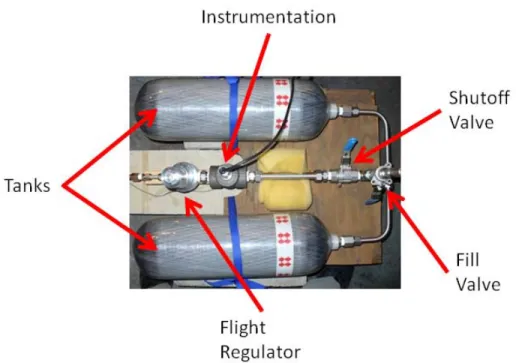
5.2.1 Instrumentation ... 74
5.2.2 Laboratory Nitrogen Cylinders ... 76
5.2.3 High Side of CGSE ... 78
5.3 Results ... 80
6 Full Eight-Thruster Flight System ... 83
6.1 Hardware Construction ... 83
6.2 Interfacing the CGSE to the TALARIS Flight Computer ... 87
6.3 Static Characterization Testing ... 89
6.3.1 Thruster Identification ... 90
6.3.2 Static Test Stand ... 90
6.3.3 Thrust Output Characterization ... 92
6.3.4 Pulse Testing and CGSE Control Circuit Improvement ... 99
9
7 Ongoing and Future Work ... 106
7.1 Validation Testing ... 106
7.1.1 Horizontal Traverse and Roll Testing ... 106
7.1.2 Vertical Test Stand ... 110
7.1.3 6-DOF Flight Testing ... 112
7.1.4 Summary of Validation Testing Efforts ... 113
7.2 Improved Characterization of Thrust Levels Throughout a Hop ... 114
7.3 Possible Upgrades ... 115
8 Conclusion ... 118
11
List of Figures
Figure 1-1. Ultra-precision landing [3]. ... 20
Figure 2-1. Prototype vehicles competing in the Northrop Grumman Lunar Lander Challenge. ... 23
Figure 2-2. Lunar Landing Research Vehicle (LLRV) in flight, 1964 [8]... 24
Figure 2-3. Diagram of ACAT lander prototype [10]. ... 25
Figure 2-4. NASA robotic lunar lander testbeds using cold gas propulsion. ... 26
Figure 2-5. USC LEAPFROG lunar lander testbed [16]. ... 27
Figure 2-6. Comparison of ballistic and hover hop trajectories [18]. ... 30
Figure 2-7. Weight/mass of propulsion systems vs. total impulse delivered [24]. ... 32
Figure 3-1. Scaling of TALARIS terrestrial hop compared to GLXP lunar hop [38]. ... 41
Figure 3-2. TALARIS cold gas thruster geometry. ... 44
Figure 3-3. CGSE system schematic [38]. ... 46
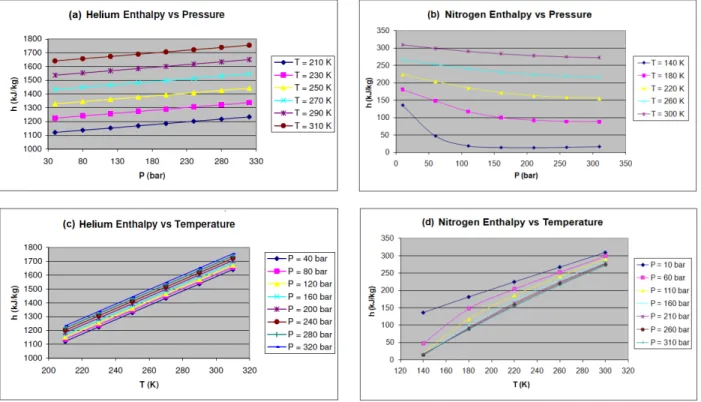
Figure 4-1. Enthalpy relations for helium and nitrogen. ... 54
Figure 4-2. CGSE MATLAB model flowchart. ... 60
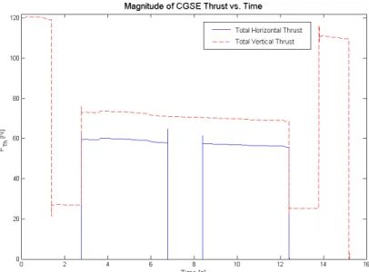
Figure 4-3. CGSE thrust profile from an example run of the MATLAB model. ... 62
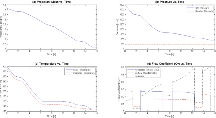
Figure 4-4. Results of the example run of the CGSE MATLAB model. ... 64
Figure 4-5. Omega SV128 solenoid valve. ... 68
Figure 4-6. Tescom 44-1363-2122-408 regulator. ... 69
Figure 4-7. Drawing of CGSE nozzle [55]. ... 72
Figure 5-1. Measurements made in single-stream thruster characterization tests [38]. ... 74
Figure 5-2. Thruster and instrumentation for single-stream characterization tests. ... 75
Figure 5-3. First configuration for single-stream characterization tests. ... 76
Figure 5-4. Second configuration for single-stream characterization tests. ... 77
Figure 5-5. CGSE high side as constructed for single-stream characterization tests. ... 79
Figure 5-6. Third configuration for single-stream characterization tests [38]. ... 79
Figure 5-7. Plots of single-stream thruster output vs. pressure [38]. ... 80
Figure 5-8. Impulse vs. pulse width for single-stream thruster producing 40 N maximum thrust [38]. .... 82
Figure 6-1. First-generation TALARIS vehicle (T-1), which did not include the CGSE. ... 83
Figure 6-2. TALARIS CGSE assembled in flight configuration on second-generation (T-2) structure [38]. . 85 Figure 6-3. Underside of the CGSE assembly [38]. ... 85
Figure 6-4. Original CGSE control circuit for a single thruster solenoid valve. ... 88
12
Figure 6-6. Identification of thrusters by number and letter. Body coordinate axes also shown [38]. ... 90
Figure 6-7. Static test stand for CGSE flight system characterization. ... 91
Figure 6-8. CGSE thrust decrease with gas usage. ... 93
Figure 6-9. Valve timing metrics [59]. ... 100
Figure 6-10. Redesigned CGSE control circuit for a single thruster solenoid valve. ... 102
Figure 6-11. Redesigned CGSE control circuit for thruster solenoid valve with hardline dump. ... 103
Figure 6-12. Simplified diagram of a commanded 40 ms thruster pulse and its actual results. ... 104
Figure 6-13. Simplified diagram of adjusted command to produce impulse of a 40 ms square pulse. ... 105
Figure 7-1. CGSE 1-DOF horizontal traverse testing on wheels. ... 107
Figure 7-2. CGSE 3-DOF horizontal traverse and roll testing on air bearing. ... 108
Figure 7-3. GNC data from 3-DOF test of TALARIS hopper, with 45° roll and horizontal traverse. ... 109
Figure 7-4. TALARIS hopper in vertical test stand, allowing both altitude and attitude control testing. . 110 Figure 7-5. Yaw disturbance rejection demonstrating 1-DOF attitude control of TALARIS hopper. ... 111
13
List of Tables
Table 2-1. Lunar lander testbed vehicles using divided propulsion architecture. ... 28
Table 4-1. Maximum modeled 𝐶𝑉 for example flight profile at several different chamber pressures. ... 66
Table 6-1. Maximum thrust levels for individual CGSE thrusters. ... 96
Table 6-2. Thruster directions as unit vectors in TALARIS body coordinates. ... 98
Table 6-3. Valve timing metrics during first CGSE flight system pulse tests [59]. ... 101
15
Notation
Acronyms and Abbreviations
ACAT Advanced Concept Architecture Test
ACS Attitude Control System
ALHAT Autonomous Landing and Hazard Avoidance Technology
CGSE Cold Gas Spacecraft Emulator
CGTA Cold Gas Test Article
CNC Computer Numerical Control
COTS Commercial Off-The-Shelf
DAQ Data Acquisition (device or system)
DOF Degree(s) Of Freedom
EDF Electric Ducted Fan
EDL Entry, Descent, and Landing
GLXP Google Lunar X PRIZE
GNC Guidance, Navigation, and Control
HTV Hover Test Vehicle
ID Inner Diameter
ILN International Lunar Network
IMU Inertial Measurement Unit
ISRU In-Situ Resource Utilization
KKV Kinetic Kill Vehicle
LAN Local Area Network
LEAP Lightweight Exo-Atmospheric Projectile
LEAPFROG Lunar Entry and Approach Platform For Research On Ground
LED Light-Emitting Diode
LLRV Lunar Landing Research Vehicle
LLTV Lunar Landing Training Vehicle
MIT Massachusetts Institute of Technology
MMH Monomethylhydrazine
MOSFET Metal-Oxide-Semiconductor Field-Effect Transistor NASA National Aeronautics and Space Administration
16
NI National Instruments
NIST National Institute of Standards and Technology
NPT National Pipe Thread
NTO Nitrogen Tetroxide
OD Outer Diameter
PVC Polyvinyl Chloride
PWM Pulse-Width Modulation
RIO Reconfigurable Input/Output (device)
SCBA Self-Contained Breathing Apparatus
SPHERES Synchronized Position Hold Engage Reorient Experimental Satellites TALARIS Terrestrial Artificial Lunar And Reduced gravIty Simulator
USB Universal Serial Bus
USC University of Southern California
WGTA Warm Gas Test Article
1D One-Dimensional
2D Two-Dimensional
Units
A ampere
bar bar (105 Pa)
Hz hertz in. inch J joule K kelvin kg kilogram kΩ kilohm lb pound m meter mA milliampere mol mole MPa megapascal ms millisecond
17
N newton
Pa pascal
psi pounds per square inch
psia pounds per square inch absolute
psig pounds per square inch gauge (relative to surrounding atmosphere)
RPM revolutions per minute
s second
SCFM standard cubic feet per minute (standard conditions of 60°F and 14.7 psia)
V volt
Vdc volts of direct current
W watt
° degree (angular measurement)
°C degrees Celsius
°F degrees Fahrenheit
Ω ohm
Variables and Constants
𝑎 constant used in the Redlich-Kwong real gas equation of state
𝐴𝑒 nozzle exit area
𝐴𝑡 nozzle throat area
𝑏 constant used in the Redlich-Kwong real gas equation of state
𝐶𝑉 flow coefficient
𝐹𝛾 specific heat ratio factor, 𝛾 1.40⁄
𝑔 acceleration due to gravity at Earth’s surface, 9.81 m/s2
𝐹𝑃 piping geometry correction factor
𝐹𝑇ℎ thrust
𝐻 enthalpy
ℎ specific enthalpy
𝐼𝑠𝑝 specific impulse
𝑀 molar mass
𝑀𝑒 Mach number at nozzle exit
18
𝑚̇ mass flow
𝑃𝑎 ambient pressure
𝑃𝑐 chamber pressure
𝑃𝑐𝑟𝑖𝑡 critical pressure (pressure at vapor-liquid critical point of a substance)
𝑃𝑒 nozzle exit pressure
𝑃1 inlet pressure
𝑃2 outlet pressure
∆𝑃 differential pressure
𝑞𝑔 volumetric flow rate
𝑄̇ heat flow
𝑅 ideal gas constant, 8.314 J/(mol K)
𝑅𝑠𝑝 specific gas constant, 𝑅 𝑀⁄
𝑆𝐺𝑔 specific gravity of gas relative to air at standard conditions of 60°F and 14.7 psia
𝑇𝑐 chamber temperature
𝑇𝑐𝑟𝑖𝑡 critical temperature (temperature at vapor-liquid critical point of a substance)
𝑇1 inlet temperature
𝑇2 outlet temperature
𝑇 𝑊⁄ thrust-to-weight ratio
𝑢 specific internal energy
𝑢𝑒 exhaust velocity
𝑢𝑒𝑞 equivalent exhaust velocity
𝑉 volume
𝑉𝑚 molar volume, 𝑀 𝜌⁄
𝑥𝑇 terminal pressure drop ratio (valve or regulator alone)
𝑥𝑇𝑃 terminal pressure drop ratio for entire assembly of valve or regulator and fittings
𝑌 expansion factor
𝑍 compressibility factor
𝛼 conical half-angle
𝛾 ratio of specific heats
𝜀 nozzle expansion ratio
𝜆 nozzle correction factor
19
1
Introduction
The TALARIS (Terrestrial Artificial Lunar And Reduced gravIty Simulator) hopper is a small prototype flying vehicle designed to serve as an Earth-based testbed for guidance, navigation, and control (GNC) algorithms that will be used to explore lunar and other planetary surfaces. To date, nearly all robotic exploration on the surface of the Moon and other planets has been done by stationary landers or wheeled rovers. Hoppers would open up new modes of exploration with their alternate form of mobility. However, because they are a new technology without the long heritage of landers and rovers, there is a greater need for testing to reduce the risk associated with hoppers. The TALARIS testbed provides the opportunity to develop and mature hopper-based GNC algorithms on Earth, which allows for a more controlled environment and easier human access for modifications, upgrades, and repairs if necessary.
A hop consists of three main phases: propulsive ascent, traverse flight, and soft landing. A commanded maneuver of this type has been performed off the Earth once, by the Surveyor 6 spacecraft on the Moon. On November 17, 1967, after Surveyor 6 had been sitting on the lunar surface for a week, the spacecraft’s three liquid-fueled vernier rocket engines were reignited and fired for 2.5 s [1]. The control system was set such that the spacecraft would tilt 7° to the west upon liftoff, and the thrust generated was sufficient to cause the spacecraft to rise to an altitude of about 3.5 m and to land 2.4 m away from its starting point. This allowed Surveyor 6 to send back images of the surface disturbances at its initial landing site, providing information on mechanical properties of the lunar surface as well as the effects of firing rocket engines near the surface. Furthermore, the displacement of the spacecraft provided a baseline for stereoscopic viewing and photogrammetric mapping of the surrounding lunar terrain [1]. However, the Surveyor 6 hop is merely the tip of the iceberg in terms of the potential value that could be gained from exploring with hoppers.
Hoppers could improve planetary exploration from both the science and engineering perspectives. Hoppers can travel more quickly than rovers, and they can also cover a greater diversity of terrain. Hoppers could fly over large obstacles and traverse steep inclines, possibly even hopping into or out of craters. They might also provide unique opportunities for science during a hop, such as low-altitude aerial observations or examinations of cliff faces or canyon walls at various heights. For more in-depth analysis of the ways in which hoppers might contribute to planetary exploration objectives, see [2] and [3]. Hoppers have certain advantages from an engineering perspective as well. For a rover, initial landing and travel over the surface involve two dissimilar types of propulsion; by contrast, a hopper can be
20
designed to use the same propulsion system for both purposes, which may allow for a simpler design. Furthermore, hoppers enable a concept known as ultra-precision landing. A traditional lander must perform high-precision GNC activities during the entry, descent, and landing (EDL) phase to ensure that it arrives at its intended landing site; however, precision can be limited by other events that may be going on during EDL, such as jettisoning insertion stages, deploying parachutes or other braking equipment, etc. A rover might be allowed a somewhat larger landing footprint, since it could potentially cover any remaining distance to the target after landing, but this would be dependent upon the rover being able to traverse the terrain between the landing site and the final destination. A hopper, however, could cover rougher or steeper terrain and travel more swiftly than most rovers, increasing the probability of success for this tactic as well as allowing greater flexibility in selection of landing sites. Thus, hoppers provide the best chance of achieving ultra-precise final positioning with lower risk and cost than performing precise GNC all the way from orbit [4]. This concept is illustrated in Figure 1-1.
Figure 1-1. Ultra-precision landing [3].
The benefits of hoppers do come with some costs. A hopper’s ultimate range is limited by the amount of propellant it can carry (though in-situ resource utilization, or ISRU, might allow for replenishment of propellant to mitigate this issue), and a flying trajectory creates a more difficult GNC problem and a higher degree of risk than traveling along the ground. Still, hoppers could be used in certain situations to expand planetary exploration capabilities as a complement to traditional landers and rovers.
While one of the long-term goals of TALARIS is to serve as a flexible testbed for a wide range of hopping applications, it is also designed for a specific, immediate purpose: participation in the Google Lunar X PRIZE (GLXP), a $30 million competition for privately-funded teams to send a robot to the Moon, travel 500 m over the surface, and transmit images and other data back to Earth [5]. The TALARIS project began early in 2008, when a small group of MIT students and faculty met with engineers from Draper Laboratory and Aurora Flight Sciences to consider entry into the GLXP competition. As part of this entry,
21
the idea of hopping was born, and it was determined that a terrestrial prototype would be needed. Draper and MIT embarked on the development of a full GNC testbed: TALARIS. Draper is slated to develop hopping GNC, and the role of the MIT TALARIS team is to support this development by providing an Earth-based testbed for Draper’s algorithms as well as some of the GNC sensors that will be used on the actual spaceflight vehicle.
This interaction between MIT and Draper gives rise to another purpose for TALARIS: demonstration of Draper’s GNC expertise and MIT’s contributions to research for space exploration. As a flying vehicle, TALARIS can show off the work done by MIT and Draper in an exciting and easily comprehensible way. This could increase interest in the GLXP competition and the potential for using hoppers for planetary explanation, and it could also contribute positively to the overall reputations of MIT and Draper for developing innovative space technology, which might in turn lead to future opportunities in terms of funding or contracts for research and development.
The dual role of TALARIS as a testbed and a demonstrator creates a unique set of design considerations and constraints. To maximize effectiveness as a demonstrator, TALARIS should be able to safely operate with people in relatively close proximity. TALARIS could also deliver extra value by being able to travel and execute demonstrations at multiple locations. This would be easiest to achieve if TALARIS did not require an extensive infrastructure (e.g. a large support frame or safety catch net) or the use of hazardous materials (including many rocket propellants). At the same time, TALARIS must meet specific performance requirements to function as an effective testbed. The interactions between these two drivers greatly affected the design of TALARIS, particularly in terms of propulsion.
The TALARIS hopper as built has two propulsion systems: (1) a system of four electric ducted fans to offset a fraction of Earth’s gravity (e.g. 5/6 for lunar simulation), and (2) a cold gas propulsion system which uses compressed nitrogen propellant to provide impulsive rocket propulsion, flying in an environment dynamically similar to that of the Moon or other target body. This thesis focuses on the second of these propulsion systems, called the cold gas spacecraft emulator (CGSE). While cold gas propulsion is a relatively mature and well-understood technology, the particular conditions of the TALARIS project shaped the process of designing, building, and testing the CGSE to make it a uniquely customized system. That process is described in depth in this thesis, partly as a detailed record of this portion of the TALARIS project, but also in hopes of illuminating some ideas of broader significance. While the CGSE is the result of a singular set of requirements, there are some lessons to be learned from its development which can be applied to the general practice of space systems engineering.
22
2
Propulsion System Architecture
Although most major architecture decisions for TALARIS were made before the work described in this thesis began, it is useful to discuss other approaches for the propulsion of prototype or simulator landers and exploration vehicles. For one thing, a brief review of the spacecraft emulator propulsion system was conducted before detailed design work began, to ensure that the decisions made for the original concept were still valid even though the TALARIS design had evolved in other areas. Furthermore, understanding the strengths and weaknesses of cold gas propulsion compared to the other options that might have been selected provides insight into the design decisions made.
2.1 Vehicles Other Than TALARIS
Since hopping is not a common method of exploring planetary surfaces, there is little precedent for prototype or testbed vehicles built for this purpose. The closest analogues to TALARIS are Earth-based lunar lander testing vehicles. Several different concepts have been developed for vehicles of this type, but they all face the problem of predicting lunar performance from tests performed on Earth. From a propulsion perspective, the major difference between Earth and the Moon is gravity; about six times more force is needed to lift an object on the Earth as compared to lifting an object of equal mass on the Moon. The atmosphere on Earth also introduces forces that are not present on the Moon, but the effects of wind can be mitigated by operating on calm days or even indoors, and drag forces for most vehicles are small compared to the forces needed to overcome gravity and to accelerate the vehicle for horizontal transit.
One approach to testing a lunar vehicle on the Earth is to simply operate the system as designed for the Moon, as long as it is powerful enough to operate in the higher gravity of Earth. Mission profiles may be scaled in terms of distance or time such that they use an equivalent amount of delta-V for a scaled flight on Earth as they would for actual operations on the Moon. This was the approach taken for the Northrop Grumman Lunar Lander Challenge, for which the goal was to simulate a descent from lunar orbit, refueling, and return to lunar orbit [7]. An equivalent task for demonstration on Earth was designed to involve taking off from a concrete pad, ascending to an altitude of approximately 50 m, flying 50 m horizontally, and landing on a second concrete pad, with refueling and a return flight within two hours and fifteen minutes. The vehicle had to remain aloft for at least 90 s on each flight for the first level of competition and 180 s on each flight for the second level [8]. The benefit of this method is that it allows for testing of both hardware and software exactly as they will be used in the real lunar mission.
23
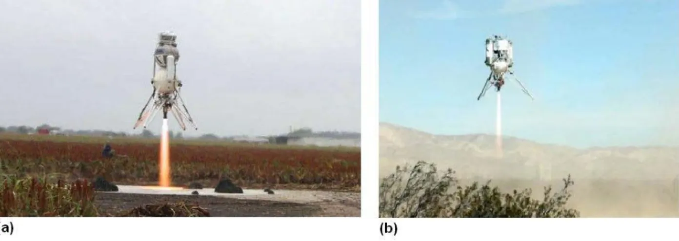
However, as stated before, this does require that the flight vehicle be robust enough to operate on Earth. In practice, this generally means that the vehicle must be large, with a high total impulse capacity. This was true of the two vehicles that completed the Northrop Grumman Lunar Lander Challenge, which are shown in Figure 2-1 below. The Armadillo Aerospace Scorpius vehicle weighed 1900 lb (862 kg) when fully loaded with ethanol and liquid oxygen propellant [6], while the Masten Space Systems Xoie vehicle weighed 850 lb (386 kg) and used isopropyl alcohol and liquid oxygen for propellant [7].
Figure 2-1. Prototype vehicles competing in the Northrop Grumman Lunar Lander Challenge. (a) Armadillo Aerospace Scorpius [6], (b) Masten Space Systems Xoie [7].
As can be seen by the settings of the photographs in Figure 2-1, test flights for both the Armadillo and Masten vehicles occurred in remote areas. This is due to the size of these vehicles, as well as the hazardous nature of their propellants, which required exceptional precautions to minimize risk to bystanders. This method of operation would not be practical for TALARIS, since TALARIS is designed to be operated by students in the urban setting of MIT and to perform in-person demonstrations for nearby observers. Also, as mentioned previously, the role of TALARIS is not only to contribute to efforts to win the GLXP, but also to serve as a platform for testing and demonstrating hopping planetary exploration in general. Thus, building TALARIS with full spaceflight hardware optimized for the Moon would not only be difficult and expensive, but it might actually decrease the overall usefulness of TALARIS as a testbed by making it less suitable to investigate operations under a wide range of conditions.
A second approach to Earth-based testing of lander vehicles is to create some sort of separation between counteracting the higher gravity of Earth and performing GNC tasks. In this case, there are two main architecture decisions to be made. The first major decision is the degree of division, or how
24
propulsion tasks will be grouped and defined. There are two basic methods of doing this. One way is to separate lift (i.e. support of the vehicle’s weight) from attitude control. The other is to devote some lift to fractional weight relief, so that the effect of Earth’s gravity on the testbed is effectively reduced to that of the Moon (or other target body), and to combine the remaining lift with attitude control to simulate the entire propulsion system that will be used on the actual lander. The second major decision is whether the two tasks will be performed by entirely separate propulsion systems, or whether there will be a single propulsion system with two separately-controlled sets of actuators. Lunar lander testbeds have been built and
flown with all four possible combinations of these divided propulsion architecture options. In fact, TALARIS took inspiration for its architecture from the Apollo program’s Lunar Landing Research Vehicle (LLRV, Figure 2-2) and its successor, the Lunar Landing Training Vehicle (LLTV). These vehicles used a gimbaled turbofan jet engine for 5/6 weight cancellation and a system of hydrogen peroxide rockets to simulate the Lunar Module propulsion, which they did with great success; Neil Armstrong credited his successful lunar landing, as well as those of his fellow Apollo astronauts, in large part to
Figure 2-2. Lunar Landing Research Vehicle (LLRV) in flight, 1964 [8].
extensive training on the LLRV and LLTV [9]. However, because they were designed to carry a human pilot, the LLRV and LLTV were much larger than TALARIS. Several more recent robotic lander simulation vehicles provide a closer comparison to TALARIS.
25
A relatively early vehicle comparable to TALARIS was built for the Advanced Concept Architecture Test (ACAT) demonstration in 1994 [10]. A small planetary lander prototype was constructed using surplus hardware from the Lightweight Exo-Atmospheric Projectile (LEAP) program for the development of kinetic kill vehicle (KKV) technology, or “hit-to-kill” ballistic missile interceptors designed for use in space. The ACAT lander (Figure 2-3), like the LLRV and LLTV, used two separate propulsion systems, but it handled the division of tasks differently. Rather than attempting to simulate a partial gravity environment, the ACAT lander used a modified version of a KKV divert propulsion system consisting of three bipropellant monomethylhydrazine/nitrogen tetroxide (MMH/NTO) thrusters for lift and a separate attitude control system (ACS) of eight cold gas nitrogen thrusters. The ACAT lander was successfully demonstrated in a test conducted in the National Hover Test Facility at Edwards Air Force Base in California, a facility built specifically for testing for LEAP and similar programs [10]. The TALARIS project does not have such a dedicated testing facility, though, and the dangers in handling rocket fuels such as MMH and NTO as well as operating a rocket engine performing combustion would likely require one. Thus, only limited aspects of the propulsion design of the ACAT lander can be applied to TALARIS. Using a cold gas system which operates on compressed gas is an alternate method of propulsion that generally cannot provide as much impulse as a system using combustible propellants but also avoids many of the safety hazards inherent in such a system. Two recent NASA robotic lander test vehicles (shown in Figure 2-4 below) were designed, built, and tested, each using a single cold gas propulsion system with two sets of actuators, but with different approaches to the division of propulsion tasks.
26
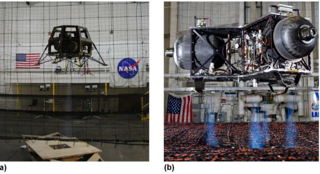
Figure 2-4. NASA robotic lunar lander testbeds using cold gas propulsion.
(a) NASA Ames Hover Test Vehicle (HTV) [11], (b) NASA Marshall Cold Gas Test Article (CGTA) [12].
The vehicle shown at left in Figure 2-4 is the Hover Test Vehicle (HTV), built at NASA Ames Research Center as an initial prototype of the Modular Common Bus, a low-cost spacecraft designed to be able to carry any science instrument fitting predefined mass and power budgets. The HTV was designed to hover at a stable altitude and position in order to test GNC algorithms; it accomplished this with one main lift and six ACS thrusters, all fed from the same pair of scuba tanks [13]. A different vehicle was developed at NASA Marshall Space Flight Center to simulate lunar landings as a risk reduction activity for robotic lunar lander flight projects, including the International Lunar Network (ILN) [14]. This Cold Gas Test Article (CGTA), shown at right in Figure 2-4 above, had one large central thruster to cancel 5/6 of Earth’s gravity and a set of smaller thrusters to lift the last 1/6 of the weight and perform attitude control, but again all were fed from a common source of compressed air [12]. Both the NASA Ames HTV and the NASA Marshall CGTA had the same problem, inherent to relying only on cold gas propulsion: short flight times. In fact, because the CGTA was limited to flights of 10 seconds or less, the NASA Marshall team built a second-generation vehicle with the same architecture but a monopropellant hydrogen peroxide propulsion system in place of the cold gas system [14]. This Warm Gas Test Article (WGTA) is expected to have flight times as long as 60 seconds [15], which will allow for longer-duration GNC testing, but the hydrogen peroxide again introduces more difficult handling and operational safety issues. The evolution of the NASA Marshall robotic lunar lander program illustrates the difficulty in finding a middle ground between high performance and a safely operable and accessible system.
27
An alternate approach to resolving this dilemma was taken by a student group at the University of Southern California (USC) for a lunar lander testbed called LEAPFROG (Lunar Entry and Approach Platform For Research On Ground) [16], shown in Figure 2-5 below.
Figure 2-5. USC LEAPFROG lunar lander testbed [16].
The architecture for LEAPFROG separated the lift and attitude control functions and performed each with a different propulsion system. A small jet engine, designed for hobby aircraft, was used to provide lift for hover and descent flight, while the ACS was composed of 12 cold gas thrusters using nitrogen propellant [16]. Because LEAPFROG, like TALARIS, was a student-run project, many of the same safety constraints and desires for simplicity of development and operation applied. Given these conditions, the architecture chosen for LEAPFROG was a good option in terms of flight time; it was designed for flights of up to three minutes [16]. However, the impulsive rocket propulsion used by an actual lunar lander creates vehicle dynamics that can be substantially different from those provided by the continuous propulsion of an air-breathing jet engine. Since the jet engine in LEAPFROG supplied essentially all the lift an actual lunar lander would require, the long flight time came at a cost of lost simulation fidelity. To sum up the various approaches taken for the design of propulsion systems for lunar lander testbeds, it is evident that there are many different architecture choices that can be made, but every design has its drawbacks. The following Table 2-1 presents a brief review of the projects using a divided propulsion architecture that were discussed in this section.
28
Table 2-1. Lunar lander testbed vehicles using divided propulsion architecture.
Task Separation
Lift & ACS Partial weight relief & simulated lander propulsion
Sy
st
em
One system, two sets of actuators
NASA Ames HTV (t) NASA Marshall CGTA (t)
NASA Marshall WGTA (p) Two separate systems LEAP/ACAT (p) USC LEAPFROG (d) Apollo LLRV and LLTV (p) TALARIS
Key to main limitations: p = hazardous propellants
d = dynamics less similar to actual lander t = short flight time
None of the three main limitations identified for lander testbed vehicles in Table 2-1 are desirable for the TALARIS project, but it is evident that some compromises must be made to achieve a successful flight vehicle design. With this in mind, a two-pronged approach was taken to optimize the propulsion architecture for TALARIS. Firstly, a unique combination of propulsion systems was selected to mitigate some of the difficulties encountered by other lander testbeds. Secondly, careful consideration was made of all the factors surrounding the TALARIS project, such that the design space was defined as fully as possible. In other words, some of the potential issues that could arise from particular propulsion system designs (such as serious safety hazards) were hard boundaries that the project could not cross, whereas others (such as imperfect dynamic similarity and short flight times) were simply undesirable attributes which should be minimized but could be areas in which to relax requirements if necessary.
2.2 Review of TALARIS Propulsion Architecture
As mentioned before, most of the major architecture decisions for TALARIS were made before the work described in this thesis began. The initial group from MIT, Draper, and Aurora made a preliminary study of GLXP vehicle concepts during January 2008 and handed their results off to the 16.89 graduate Space Systems Engineering design class at MIT in spring of that year. This class settled on a hopping mode of travel for the exploration vehicle and proposed that an Earth-based testbed vehicle be built to develop the concept further. A special graduate design class (16.898) was held in fall 2008, in which a basic architecture of dual propulsion systems was devised. As shown by the placement of TALARIS in Table 2-1, this architecture called for two separate propulsion systems, divided into the tasks of weight relief and simulation of lunar propulsion. It was believed that this architecture would provide the most
29
accurate conditions for testing GNC algorithms, and it had proven remarkably successful in the past with the LLRV and LLTV. Furthermore, keeping the simulated lunar propulsion entirely separate from weight relief meant that theoretically, software written for the TALARIS testbed could be moved directly over to control the actual GLXP hopper. Overall, the selected architecture was deemed to make TALARIS the most effective possible testbed for the GLXP hopper and a robust demonstrator of hopping in general. In the 16.898 class, electric ducted fans (EDFs) were selected for the weight relief propulsion system, required to lift 5/6 of the vehicle’s Earth weight at all times [17]. This decision clarifies some of the priorities of the TALARIS project. For instance, another option for weight relief might have been to devise some system of pulleys and counterweights from which to suspend the hopper. This would have had the benefit of little to no reliance on expendable propellant, thus allowing for longer flight times. However, it also would have had the drawbacks of restricting the flight range of the vehicle, introducing dynamics from the suspension tethers, and requiring a large amount of infrastructure to be moved with the vehicle for tests or demonstrations at a different site. The decision to make TALARIS a free-flying vehicle reveals that simulation fidelity and flexibility in operations are more important to the project than maximizing flight times at all costs. At the same time, it is important that flight times not be so short as to preclude the collection of useful data or make it difficult to demonstrate all the phases of a hop. The selection of a weight-relief propulsion system for TALARIS that makes use of the air through which it flies was made to maximize efficiency and flight times as much as possible, creating a propulsion architecture more similar to that of the USC LEAPFROG testbed with its flight times of several minutes as opposed to the NASA cold gas vehicles limited to flights of just seconds. Finally, the choice of the EDFs over other aerodynamic propulsion methods (such as rotors or small jet engines like the JetCat used by LEAPFROG) illustrates that beyond performance metrics such as propellant usage, thrust output, and system mass, other factors such as cost, safety, and ease of implementation were also considered. The 16.898 class also selected cold gas propulsion to emulate the actual GLXP spacecraft propulsion system while operating in an artificial lunar gravity environment created by the constant weight offset from the EDFs. After the 16.898 class concluded in fall 2008, the 16.83/89 Space Systems Engineering class held in spring 2009 developed the design of the TALARIS testbed further, but due to limited resources they were only able to focus on one of the propulsion systems. They chose to work on the EDFs, and by the end of the semester they had built a first-generation vehicle that flew in a test stand constraining it to linear vertical motion only [17]. However, the cold gas propulsion system remained at the conceptual design stage when the work described in this thesis began.
30
2.3 Confirming the Decision to Use Cold Gas Propulsion
In summer 2009, detailed design work for the TALARIS spacecraft emulator propulsion system began. One of the first tasks undertaken was a review of the decision to use a cold gas propulsion system for this purpose. While a good deal of thought had been put into this decision in earlier stages of the TALARIS project, it was deemed necessary to revisit the question in light of the progress that had been made over time. This process not only confirmed that cold gas propulsion was the optimal choice for the spacecraft emulator propulsion system, but it also highlighted strengths and weaknesses that shaped the design of the cold gas propulsion system for TALARIS.
2.3.1 General Hopper Propulsion Design Considerations
One major design driver for the TALARIS spacecraft emulator propulsion system was hop trajectory. Two types of trajectories were considered. The first is the ballistic hop, in which the hopper’s propulsion system provides an initial acceleration to the vehicle at launch and, if necessary, a deceleration at the end of flight for a softer landing. The majority of a ballistic hop is an unpowered coasting phase. For example, as discussed in Chapter 1, the Surveyor 6 probe performed a ballistic hop on the Moon; the accelerations involved were small enough that a braking phase was not required. The second type of trajectory is called the hover hop. In a hover hop, the vehicle ascends to a given height above the surface, translates horizontally while maintaining constant altitude and attitude, and descends vertically to a soft touchdown. Both the ballistic and hover hop trajectories are illustrated in Figure 2-6.
31
Ballistic hops tend to use less propellant than hover hops, since the duration of powered flight is shorter, but performing precision hops with a ballistic trajectory may be more difficult because of the narrow window of time available to make powered maneuvers. By contrast, hover hops tend to consume more propellant because the entire trajectory is powered, but this also allows the hopper to perform attitude control and course corrections mid-hop. A detailed analysis of the tradeoffs between these two types of hops is available in [18].
Selection of a hop trajectory influences the propulsion options available to a hopper. For example, designs have been proposed for hoppers using mechanical methods such as springs or pistons to exert a reaction force on a surface; see for instance [19,20,21,22]. However, mechanical hopping can only be ballistic, while the current concept of operations for the GLXP lunar hop calls for covering the mandated 500 m distance by hover hopping [18]. Furthermore, as described in Chapter 1, there are potential benefits to using the same propulsion system for initial landing on a planetary surface and later hopping travel. A mechanical method of hopping would not be very useful for an initial landing; rocket engines are much more appropriate for this purpose. Additionally, an impulsive rocket propulsion system capable of performing a hover hop could also be used to perform a ballistic hop if desired by simply firing the rockets only at the beginning and end of the flight. Thus, the TALARIS vehicle is designed to use rocket propulsion, in order to provide the most accurate simulation of the planned GLXP trajectory as well as to allow TALARIS to be a testbed for the greatest possible range of hopping applications.
There are many types of rocket propulsion systems, but not all are appropriate for hoppers. Because the propulsion system for a hover hop is required to perform attitude control as well as to provide acceleration to make the vehicle travel, it must be able to stop, restart, and deliver small impulse bits. Even ballistic hoppers, if they are designed to make multiple hops, require stop and restart capability for their propulsion systems. This rules out solid rockets. Hybrid rockets are a theoretical possibility, but they have much less flight heritage, and hybrid rocket development has generally been focused on high-thrust applications like launch vehicles and orbit insertion stages [23]. The remaining feasible options, for both the GLXP and TALARIS hoppers, are cold gas, monopropellant, and bipropellant propulsion. Cold gas, monopropellant, and bipropellant systems all have extensive flight heritage. Of the three, cold gas systems are the least complex and costly, but they generally have the lowest thrust and specific impulse; bipropellant systems have the highest complexity and cost, but also the highest thrust and specific impulse; and monopropellant systems fall between the other two [24]. Higher complexity means that more hardware is necessary, and the additional hardware mass outweighs the performance gains
32
from the higher specific impulse when total impulse requirements are low. Figure 2-7 illustrates this relationship between system mass and total impulse.
Figure 2-7. Weight/mass of propulsion systems vs. total impulse delivered [24].
The relationship illustrated in Figure 2-7 is reinforced by consideration of the lander testbeds discussed in section 2.1. The large vehicles that competed in the Northrop Grumman Lunar Lander Challenge used bipropellant propulsion because those systems can deliver the large amount of impulse needed with the lowest mass possible. By contrast, the smaller vehicles like the ACAT lander and the NASA test vehicles used monopropellant and cold gas propulsion, since those systems have better performance in the lighter weight range.
The design of the GLXP hopper, including size and impulse requirements, has not yet been finalized, although monopropellant hydrazine has been suggested for its propulsion system [17]. But all three types of propulsion systems under consideration behave similarly – they all control thrust by varying propellant flow, and all can be designed to have a pulsed operation mode for attitude control – so the TALARIS hopper should be able to provide an accurate simulation of the GLXP hopper regardless of the particular rocket propulsion system chosen for each vehicle.
33
2.3.2 Comparison of Cold Gas and Monopropellant Systems
Mass was used as an initial guide for propulsion system type selection for the TALARIS hopper. As mentioned earlier, the 16.898 class in fall 2008 developed an initial conceptual design for a spacecraft emulator propulsion system using nitrogen cold gas propellant; the estimated mass of this system was 17 to 20 kg (37.5 to 44.1 lbs) [25]. However, after evolving the design of the rest of the TALARIS vehicle, the 16.83/89 class in spring 2009 recommended reducing the mass of the cold gas system to 10 kg (22.0 lbs) [26]. As shown in Figure 2-7, these masses are in the range where the most efficient propulsion system type in terms of highest total impulse for lowest system mass begins to transition from cold gas to monopropellant. Thus, it was decided to examine in depth whether a monopropellant system might be a better choice than cold gas for the TALARIS spacecraft emulator propulsion system.
Monopropellant systems can offer a significant improvement in specific impulse (𝐼𝑠𝑝) over cold gas
systems. Most cold gas propellants have an 𝐼𝑠𝑝 of less than 100 s (though helium gas can provide an 𝐼𝑠𝑝
of about 180 s)1
27
, while hydrazine, the most commonly used monopropellant, has an 𝐼𝑠𝑝 of
approximately 230 s [ ]. However, hydrazine is toxic and carcinogenic, and products of its decomposition include ammonia gas, which can also pose health hazards [28]. Thus, an alternative monopropellant was considered for the TALARIS hopper: hydrogen peroxide. It has an 𝐼𝑠𝑝 of about 150 s
[27], which is not as good as hydrazine but still better than most cold gas propellants. More importantly, while hydrogen peroxide still requires careful handling, it is not as hazardous as hydrazine, and the products of its decomposition are oxygen gas and water, which are not harmful to humans [29]. Hydrogen peroxide was believed to be the monopropellant most likely to work within the safety constraints of the TALARIS project.
The concept of a hydrogen peroxide monopropellant system was compared to cold gas propulsion in the following aspects:
Impulse
As mentioned above, hydrogen peroxide has a better specific impulse than most cold gas propellants. However, it is also important to note that hydrogen peroxide is a liquid propellant and thus far denser than cold gas propellants. Therefore, hydrogen peroxide provides more impulse not only on a per-mass
1 When used as a cold gas propellant, hydrogen (H
2) has a very high 𝐼𝑠𝑝 at almost 300 s, but it is almost never used
34
but also on a per-volume basis. This is important because propellant volume is limited on the TALARIS hopper; tanks must have certain dimensions to fit on the structure with the many components of the other subsystems of the vehicle. But regardless of whether mass or volume were the limiting factor on how much propellant TALARIS could carry, hydrogen peroxide would be able to provide more total impulse than most candidate cold gas propellants.
System components
A cold gas propulsion system is composed of relatively few types of components: propellant tanks, valves for filling the system and relieving excess pressure, plumbing (feed line tubes and possibly filters), a pressure regulator (though this is not used in a blowdown system), and thrusters with control valves and nozzles. A monopropellant hydrogen peroxide system can be built from these same types of components, with a few additions. The main addition would be catalyst beds, to start the exothermic decomposition of hydrogen peroxide to water and oxygen. These may be made relatively simply from stacked screens of silver wire mesh [29]. A separate pressurant tank and regulator might also be added if a regulated system were desired, but the effects of maintaining a constant thruster inlet pressure are substantially less noticeable for a monopropellant system than for a cold gas system, since the exothermic decomposition of a monopropellant generally has a much greater effect on the thruster chamber pressure than the initial pressure of the propellant. As a result, regulated monopropellant systems are generally thought to have unnecessary complexity and cost, and blowdown monopropellant systems are far more common [24]. Overall, a blowdown hydrogen peroxide system would not require many more components than a cold gas propulsion system, though size, mass, materials, etc. of analogous components would likely vary between the two types of systems.
Phase of propellant
Though the liquid phase of hydrogen peroxide has certain benefits as discussed in the Impulse section, it also has drawbacks. One challenge is ensuring proper propellant flow; since TALARIS is designed to operate on Earth, it could have a gravity-fed system, but this would require that the propellant tank be located above the thrusters, which would add additional constraints to the already difficult problem of placing all required components on the vehicle. Also, liquid hydrogen peroxide would be subject to slosh, which could not only complicate tank drainage but also add undesirable dynamics to the entire TALARIS vehicle. These effects could be mitigated with an appropriate propellant tank, perhaps including baffles or a diaphragm, but this would add complexity to the system design.
35
Handling propellant
There are several aspects to consider in regards to propellant handling. One is materials compatibility. This is especially critical in the case of hydrogen peroxide, because incompatible materials or impurities in an otherwise compatible material could not only lead to corrosion or other damage to components but also possibly catalyze the exothermic decomposition reaction before the propellant reaches the thrust chamber, causing extensive damage or injuries to personnel. The primary compatible materials recommended for a hydrogen peroxide system are certain alloys of aluminum and stainless steel, passivated with a chemical solution to form a protective layer of oxide on the surface of the metal before use, though various polymers are acceptable for use with lower concentrations of hydrogen peroxide and/or on a short-term basis [30]. This constraint would limit the materials available for use in the TALARIS propulsion system, and it would require additional care and procedures to be taken during construction, but it would likely not be an insurmountable obstacle. As for a cold gas system, materials compatibility depends on the propellant chosen, but many of the leading candidates (such as nitrogen and helium) are inert gases, which have few restrictions on the materials with which they can be used. Another aspect of propellant handling is personal protective equipment. When using high-concentration hydrogen peroxide, splash protection is required, including a face shield and chemical safety goggles, a PVC or rubber suit, and chemical-resistant boots [29,30]. This would not be quite as expensive or cumbersome as the equipment required to handle a more hazardous chemical like hydrazine, which requires a self-contained breathing apparatus [29]. Still, personal protection against hydrogen peroxide is a good deal more involved than the precautions recommended for work with most compressed gases, which may be as simple as wearing safety goggles [31].
Overall, there are more extensive propellant handling concerns associated with hydrogen peroxide than with most cold gas propellants. However, handling procedures for hydrogen peroxide have been well-documented, and a workable situation could be developed with some additional investments of time, money, equipment, and training.
Obtaining and storing propellant
Obtaining cold gas propellants is relatively straightforward; both MIT and Draper have standing contracts with companies such as Airgas through which cylinders of various compressed gases can be purchased. These cylinders come with protective caps and can be safely stored in many locations, as long as they can be securely attached to a wall or other large solid object like a lab bench with a belt or chain [32].
36
Hydrogen peroxide at the concentrations needed for use as a rocket propellant is far less readily available. The hydrogen peroxide available in drugstores for cosmetic and antiseptic purposes is generally at only 3% concentration in aqueous solution, hydrogen peroxide for laboratory use is available at 30-35% concentration, and concentrations from 50 to 70% are used for many industrial purposes such as bleaching of textiles and paper, but propellant-grade hydrogen peroxide ranges in concentration from 70 to 98% [33]. This presents two difficulties that were identified during this trade study between propellant system types. Firstly, at the time the work described in this thesis was being performed, few companies offered hydrogen peroxide for sale at propellant-level concentrations, though there was at least one supplier (FMC Industrial Chemicals) located in the United States [33]. Secondly, the concentration of propellant-grade hydrogen peroxide was so much higher than that commonly used in the laboratory that there were no suitable existing storage facilities at MIT, nor any personnel trained to receive and handle the chemical. Again, there is a good deal of literature available describing protocols for safe storage of highly concentrated hydrogen peroxide (see, e.g., [30] and [34]), and several companies that sell propellant-grade hydrogen peroxide or related components also offer training sessions or other consulting services which the TALARIS project could utilize [33,35]. However, this is clearly another area in which considerably more resources would have to be expended to create a safe and working hydrogen peroxide system than for a cold gas system.
Summary
To summarize, a monopropellant hydrogen peroxide propulsion system would almost certainly have a higher performance than a cold gas propulsion system of equivalent mass, given the expected properties of the TALARIS hopper. However, a hydrogen peroxide system would also have more design constraints and be more complex, though not prohibitively so. Furthermore, there are many more serious safety issues related to hydrogen peroxide than to cold gas propellants, and a great deal of preparation and training would be needed to protect personnel. This is an especially large commitment due to the high turnover of students working on TALARIS; each semester, new students join the project, while some experienced students graduate or otherwise move on. None of these drawbacks are insurmountable obstacles on their own. However, when added together, they represent a significantly greater investment of resources in the development of the TALARIS spacecraft emulator propulsion system. Time was deemed to be an especially critical resource; given the competitive nature of the GLXP, the TALARIS vehicle had to demonstrate at least some hopping capability as soon as possible. Thus, it was decided to continue designing a cold gas propulsion system for the TALARIS hopper. Development of the TALARIS spacecraft emulator propulsion system could thus proceed more rapidly,
37
and if the cold gas system was found to be lacking in performance after initial demonstration, the question of investing more resources into development of a hydrogen peroxide propulsion system might be revisited. (As discussed in section 2.1, this is the path that the NASA Marshall team followed in moving from the CGTA to the WGTA. However, it was anticipated that because the TALARIS hopper had air-breathing EDFs for weight relief, the cold gas propulsion system on TALARIS would be less taxed than the propulsion system of the Marshall CGTA, and therefore flight times for TALARIS would not be limited quite so severely.) A possible framework for the process of upgrading from cold gas to monopropellant hydrogen peroxide is presented in section 7.3 as part of the discussion of future work.
2.4 Selection of Nitrogen Propellant
One final decision was made before proceeding with the detailed design of the TALARIS cold gas spacecraft emulator (CGSE) propulsion system: which particular gas to use as a propellant. This affects component selection in terms of sizing and allowable materials. Many different gases have been used for cold gas propulsion, including nitrogen, helium, carbon dioxide, air, and Freon, among others [24,27]. Selection among the numerous possible gas options was based on several factors. Chief among them were non-reactivity, to minimize materials compatibility issues, and readiness of availability. Eventually, the field was narrowed to four gases that were considered in greater detail, as described below.
Carbon dioxide (CO2)
Carbon dioxide was considered mainly because it was used effectively for small satellite cold gas propulsion for SPHERES (Synchronized Position Hold Engage Reorient Experimental Satellites), another MIT project with which many TALARIS team members were familiar [36]. In SPHERES, the carbon dioxide is stored in mixed liquid and gas phase. As the gaseous CO2 is used as propellant, the liquid CO2
evaporates to replenish it, keeping the pressure inside the propellant tank constant until all the liquid evaporates [37]. This helps keep thruster performance constant, and storage in the high-density liquid phase means that a relatively large mass of propellant can be carried. However, the drawbacks to liquid hydrogen peroxide discussed in section 2.3.2 apply to liquid CO2 as well, and these were considered
serious enough that carbon dioxide was discarded as an option. (Also, modeling of hops as described in section 4.1 revealed that TALARIS uses propellant at a much more rapid rate than SPHERES, raising concerns as to whether carbon dioxide could evaporate rapidly enough to continuously supply gaseous propellant to the TALARIS thrusters.)
38
Helium (He)
Helium was considered because of its high specific impulse; as previously mentioned in section 2.3.2, it has an 𝐼𝑠𝑝 of approximately 180 s, which is very high for an inert gas propellant. However, helium also
has a very low density, which means that it requires either a large volume or very high pressure for storage of sufficient propellant mass. This often translates to a heavier propellant tank weight, which can reduce some of the gains from the high 𝐼𝑠𝑝. Furthermore, helium systems are especially prone to
leaking [24]. And finally, helium gas is more expensive than the other propellant options considered. For these reasons, helium was not selected as the primary TALARIS CGSE propellant; however, it was kept in mind as a secondary option, and the MATLAB model described in section 4.1 was written such that helium could be easily substituted in as the modeled propellant if desired.
Nitrogen (N2)
Nitrogen gas has only a mediocre 𝐼𝑠𝑝 of 60 to 80 s [27,28]; it is strongly outperformed by helium in terms
of specific impulse alone. However, nitrogen is denser and less prone to leaking than helium, and it is also less expensive. It is a common choice for cold gas propulsion systems, as illustrated by the other vehicles described in section 2.1; all of the small robotic testbeds used a cold gas nitrogen system for at least part of their propulsion. Nitrogen gas was found to be a good compromise for the TALARIS hopper as well, and it was chosen as the propellant for which the CGSE was designed.
Air
Because air is about 78% nitrogen, it has a very similar 𝐼𝑠𝑝 – generally about 2 s lower than that of
nitrogen at the same conditions [27,28]. It was thought that air might be obtained for less expense than pure nitrogen. However, there was no equipment readily available to compress air to the high storage pressures desired. Furthermore, the MATLAB model described in section 4.1 indicated that the temperature of the gas in the CGSE would fall well below the freezing point of water. Thus, besides a compressor, a dessicator would also be needed to remove water vapor from the air. Once the cost of this equipment was considered, the potential cost savings of using air instead of nitrogen were negated. Overall, the TALARIS propulsion system architecture was the result of many decisions made for best possible performance of the system considering many factors beyond the physical characteristics of the vehicle itself, including an aggressive project schedule and a limited budget, as well as especially rigorous safety requirements. These factors continued to influence the decisions made about the TALARIS spacecraft emulator propulsion system through the detailed design phase and into testing.
39
3
TALARIS CGSE Design Framework
After the major architecture decisions had been made for the TALARIS spacecraft emulator propulsion system, the next step was detailed design. The goal of this development process was not to develop a radically new propulsion system, which would have been extremely difficult given the limited budget and relatively short deadlines of the TALARIS project; cold gas propulsion technology is mature enough that there is little room for drastic improvement. Rather, the aim of the process described in this thesis was to make specific choices that most effectively satisfied the particular needs of the TALARIS project while working within the generally well-established framework of cold gas propulsion system design.
3.1 CGSE Requirements Definition
The architecture definition process had placed some constraints on the design problem, such as the decision that the spacecraft emulator propulsion system would be a cold gas propulsion system, as well as a set of functional requirements. But in order to have definite targets to which to design the TALARIS CGSE, the process of requirements definition had to be carried further forward. The requirements already determined were used to derive quantifiable performance requirements.
3.1.1 Functional Requirements
The decisions to (1) divide the TALARIS propulsion tasks into weight relief and spacecraft emulation, each performed by a separate system, and (2) design for the performance of a hover hop led to three main functional requirements for the TALARIS spacecraft emulator propulsion system. They were:
(1) The CGSE shall lift the TALARIS hopper’s lunar weight, defined as 1/6 of its Earth weight.
Though the long-term goals for the TALARIS project include simulation of operations on a range of target bodies, the short deadlines for the GLXP made simulation of lunar operations the top priority. Furthermore, a CGSE capable of lifting the TALARIS hopper under lunar gravity could also function for many other targets with even lower gravities, including Saturn’s moon Titan2
2 Titan has a surface gravity of 0.138𝑔, while Earth’s Moon has a surface gravity of 0.166𝑔 [
or a variety of asteroids, if EDF output could be increased to provide a higher fraction of weight relief. If later operations on a body with higher gravity than the Moon, such as Mars, were desired, upgrades would be necessary unless the CGSE far exceeded its design goals. However, it was essential to set initial numerical design targets for the CGSE, and designing for lunar gravity was selected for the requirement.
40
(2) The CGSE shall propel the hopper horizontally.
This is a key difference between TALARIS and the lunar lander testbeds described in section 2.1. Although several of the lander testbeds were capable of traveling horizontally, it was not their primary function. By contrast, horizontal transit over a significant distance is the main goal of hopping, so it was a major design driver for the TALARIS CGSE from the start.
(3) The CGSE shall provide attitude control for the TALARIS hopper.
TALARIS was designed to simulate the functions of a lunar or planetary hopper as completely as possible. Since an actual hopper operating off the Earth would have only its rocket propulsion system, this meant that the TALARIS hopper testbed should ideally rely only on the CGSE for attitude control for maximum similarity, using the EDFs only for passive weight relief. The goal was to design TALARIS such that under nominal operations, where the EDFs were providing pure vertical weight relief, the CGSE would be capable of executing all attitude adjustments necessary to simulate a full hop.
These three functional requirements were the starting point for the requirements flowdown process described in this section.
3.1.2 TALARIS Flight Profile
A more specific definition of the TALARIS flight profile was necessary to proceed with requirements flowdown. As defined in section 2.3.1, a hover hop has three phases: vertical ascent, horizontal transit, and vertical descent. But more precise dimensions had to be assigned to each of these phases.
The TALARIS hopper was primarily designed to simulate the GLXP hopper. However, as discussed in section 2.3.1, it was known that the GLXP hopper would likely have a propulsion system with a higher total impulse capability than the TALARIS hopper, largely because the GLXP hopper would not have to adhere to such strict safety restrictions and could thus use energetic rocket propellants. Thus, the TALARIS hopper was designed to fly a scaled-down version of the planned GLXP hop that still contained all the accelerations that the GLXP hopper would experience in order to retain dynamic similarity. A comparison of the TALARIS and GLXP hops is shown in Figure 3-1.
![Figure 2-7. Weight/mass of propulsion systems vs. total impulse delivered [24].](https://thumb-eu.123doks.com/thumbv2/123doknet/14732255.573263/32.918.167.758.190.620/figure-weight-mass-propulsion-systems-total-impulse-delivered.webp)
![Figure 3-1. Scaling of TALARIS terrestrial hop compared to GLXP lunar hop [38].](https://thumb-eu.123doks.com/thumbv2/123doknet/14732255.573263/41.918.114.810.159.369/figure-scaling-talaris-terrestrial-hop-compared-glxp-lunar.webp)
![Figure 3-3. CGSE system schematic [38].](https://thumb-eu.123doks.com/thumbv2/123doknet/14732255.573263/46.918.122.812.108.458/figure-cgse-system-schematic.webp)
![Figure 4-7. Drawing of CGSE nozzle [55].](https://thumb-eu.123doks.com/thumbv2/123doknet/14732255.573263/72.918.150.767.105.517/figure-drawing-of-cgse-nozzle.webp)