HAL Id: insu-00933529
https://hal-insu.archives-ouvertes.fr/insu-00933529
Submitted on 20 Jan 2014
HAL is a multi-disciplinary open access
archive for the deposit and dissemination of
sci-entific research documents, whether they are
pub-lished or not. The documents may come from
teaching and research institutions in France or
abroad, or from public or private research centers.
L’archive ouverte pluridisciplinaire HAL, est
destinée au dépôt et à la diffusion de documents
scientifiques de niveau recherche, publiés ou non,
émanant des établissements d’enseignement et de
recherche français ou étrangers, des laboratoires
publics ou privés.
submersibles for fine-scale geomorphology studies
Nina Stark, Nicolas Le Dantec, Pablo Corella Juan, Andrew Barry David,
Ulrich Lemmin, Stéphanie Girardclos, Achim Kopf
To cite this version:
Nina Stark, Nicolas Le Dantec, Pablo Corella Juan, Andrew Barry David, Ulrich Lemmin, et al..
De-ployment of a dynamic penetrometer from manned submersibles for fine-scale geomorphology studies.
Limnology and Oceanography : methods, 2013, 11, pp.529-539. �10.4319/lom.2013.11.529�.
�insu-00933529�
Dynamic penetrometers are easily deployable tools for in situ estimation of marine sediment strength. They are used for, e.g., the investigation of marine and lacustrine slope sta-bility, geology, sedimentation, and sediment dynamics. Con-cerning the latter, variations in the sediment texture, the state of consolidation, and density can be identified from the derived vertical profile of sediment strength, possibly indicat-ing and quantifyindicat-ing sediment deposition or erosion (Stark and Kopf 2011). A number of different designs are currently used to address such tasks. For deep waters, heavy lance-like systems are mainly applied (Beard 1981; Stegmann and Kopf
2007). The devices used in shallow waters (<200 m) include lance-like systems based on standard Cone Penetration Test geometries (Stegmann et al. 2006; Mosher et al. 2007), full-flow penetrometers minimizing effects of side adhesion and side friction (Mulhearn 2003; Yafrate et al. 2009), fluid-dynamic shaped penetrometers emphasizing free-fall per-formance that are decoupled from ship/platform movements (Stoll and Akal 1999; Stark et al. 2009) and specially designed penetrometers, e.g., for simulating mine burial (Poeckert et al. 1996). As all systems are usually deployed from a vessel or platform at the water surface, the spatial precision of the tar-geted penetration position at the seafloor is often limited to several meters depending on the water depth and the stabil-ity of the vessel (Mulhearn 2003; Stark et al. 2011). Generally, this spatial resolution is sufficient to map and profile the sed-iment strength in survey areas such as bays, river deltas, estu-aries, and slopes, as well as along big to medium-sized
geo-Deployment of a dynamic penetrometer from manned
submersibles for fine-scale geomorphology studies
Nina Stark
1,2*, Nicolas Le Dantec
3,4, Juan Pablo Corella
5,6, David Andrew Barry
3, Ulrich Lemmin
3,
Stéphanie Girardclos
5, and Achim Kopf
11MARUM–Center for Marine and Environmental Sciences, University of Bremen, Leobener Str, 28359 Bremen, Germany 2Virginia Tech, Civil and Environmental Engineering, Patton Hall, Blacksburg, VA 24061, USA
3Laboratoire de technologie écologique, Institut d’ingénierie de L’environnement, Faculté de L’environnement naturel,
archi-tectural et construit (ENAC), École Polytechnique Fédérale de Lausanne (EPFL), Station 2, 1015 Lausanne, Switzerland
4LGCE, CETMEF, Technopôle Brest Iroise BP 5, 155 rue Pierre Bouguer, 29280 Plouzané, France 5Institut Forel, University of Geneva, 10 route de Suisse, 1290 Versoix, Switzerland
6Museo Nacional de Ciencias Naturales (MNCN-CSIC), Serrano 115bis, 28006 Madrid, Spain
Abstract
Dynamic penetrometers reveal information about seafloor strength, stratification, stability, and sediment remo-bilization. However, positioning is often limited to a range of meters making it difficult to target small-scale geo-morphologic features. Deployments from submersed vessels (manned or remotely operated) can extend the possi-bilities of in situ geotechnical surveying in areas of complex bathymetry. The lightweight dynamic penetrometer
Nimrod was modified to enable its deployment from the MIR submersibles, and was deployed during two dives in
the Rhône Delta and Vidy Bay (both Lake Geneva). In the Rhône Delta, five positions at the floor/levee complex of a submarine canyon were sampled with ~1 m spacing, with good reproducibility of the results. In Vidy Bay, so-called pillow-hollow structures on the lake bottom with dimensions of about 50 cm were targeted. At both sites, the penetrometer was released from a height of about 1-2 m above the lake bottom using the starboard robotic arm of the MIRs leading to impact velocities of ~ 3 m s–1. The probe reached penetration depths of up to 80 cm
with maximum decelerations of up to 2.9 g. Stratification in the deceleration versus penetration depth profiles hinted at recent sediment remobilization processes. Pressure transducer results of the probe were suitable to deter-mine water depth, and estimate trends of excess pore pressure. This article describes the modification of the dynamic penetrometer Nimrod for deployments from the MIR submersibles, assesses the deployment performance, validates the results, and gives an outlook on the application of this technique and the results.
*Corresponding author: E-mail: [email protected]
Acknowledgments
Full text appears at the end of the article. DOI 10.4319/lom.2013.11.529
Limnol. Oceanogr.: Methods 11, 2013, 529–539
© 2013, by the American Society of Limnology and Oceanography, Inc.
and
morphologic features such as dunes or sandbars (Stark et al. 2011). However, the spatial accuracy reached in water depths in excess of 10 m by surface deployments (≥3 m) is not suit-able to investigate fine-scale geomorphologic features such as ripple structures (Ashley 1990), pillow-hollow features in the range of decimeters (Lang 1989; Brandl et al. 1993), or narrow and steep canyons (Inman et al. 1976). Pillow-hollows are well-rounded, cushion-like structures staggered over the lake bottom and usually separated by comparatively narrow troughs (Vernet 1966; Le Dantec et al. 2013). These peculiar bedforms are small-scale features, with “pillows” being about 50 cm in diameter and “hollows” about 10-20 cm in depth. Bottom boundary layer processes are affected by such sedi-mentary structures. Sedimentological studies carried out on short cores collected in pillows and hollows indicate differ-ences in the geochemistry of surface sediment (Dominik et al. 1992; Brandl et al. 1990), which influences the transforma-tion reactransforma-tions and the fate of compounds in the benthic layer. In addition, repeated observations of Burbot fish activ-ity at the lake bottom confirm that the “hollows” are a habi-tat for this bottom-dwelling fish (Vernet 1966; Dominik et al. 1989; Le Dantec et al. 2013). The spatial accuracy of dynamic penetrometer surface deployments, in the case of water depths in excess of several meters, is not sufficient to target, e.g., crests and troughs of such small-scale geomorphological features, respectively. Furthermore, erosion-deposition processes can also lead to a high spatial variation of surficial sediments without showing significant geomorphological features (Downing and Rath 1988). The required high spatial accuracy with regard to the targeted geomorphological fea-ture can be addressed through visual site supervision during surveying, either by deploying one of the lightweight systems (e.g., eXpendable Bottom Penetrometer, Nimrod) with diver support in shallow waters, or by using Remotely Operated Vehicles (ROVs) or manned submersibles in deep waters. Yet, exact position in terms of latitude and longitude of underwa-ter vehicles is not necessarily betunderwa-ter than with free fall sys-tems. The modification of the dynamic penetrometer Nimrod, used in geotechnical investigation of subaqueous sediment dynamics, for deployments from manned submersibles or ROVs was motivated by the objective to carry out geotechni-cal investigations of sea-/lakebed sediments showing a high spatial heterogeneity at water depths exceeding the range accessible to divers.
In the framework of the éLEMO project (http://www.elemo.ch, last accessed 26 May 2013), the two manned submersibles MIR1 and MIR2 operated by the Russian Academy of Sciences were deployed in Lake Geneva to investigate lake processes in Vidy Bay, the deep basin of Lake Geneva and the Rhône Delta submarine canyons (Fig. 1). The overall objective of the éLEMO research project was to improve the understanding of water and sediment dynamics in Lake Geneva, in the context of quality assessment and management of water resources. Geotechnical in situ surveys using dynamic penetrometers at
all three éLEMO research sites were part of the lakebed inves-tigation strategy. However, in areas with pillow-hollow struc-tures such as Vidy Bay (Vernet 1966; Dominik et al. 1989; Sas-tre et al. 2010) and in the Rhône canyons, water depths of 25-110 m limited the geotechnical analysis of fine-scale struc-tures by dynamic penetrometer deployments from the lake surface. Thus, dynamic penetrometer deployments were undertaken from the MIRs during several dives with the objec-tives of (i) testing a modification of the penetrometer tail design suitable for handling by the robotic arm of the MIR submersible, and (ii) developing a deployment strategy for the investigation of fine-scale structures by carrying out pen-etrometer drops under visual surveillance of the lake bottom. These measurements complemented an extensive geotechni-cal characterization of surficial sediments, as part of a larger effort to investigate sediment dynamics in Lake Geneva. This effort included Nimrod deployments from the lake surface along 15 transects in the Rhône Delta in the eastern lake up to water depths of 161 m (85 positions), along 3 main transects in Vidy Bay (38 positions), and along 2 transects over the sill at the junction with the narrower and shallower western lake (15 positions). For instance, geotechnical measurements con-tributed to a multidisciplinary study on contemporary sedi-mentation and erosion processes in Lake Geneva’s active sub-aquatic canyon in the Rhone Delta (Corella et al. 2013). More generally, coupling results on properties of lake-bottom sedi-ment with observations and numerical simulations of near-bottom currents derived from studies on lake hydrodynamics will improve our knowledge of sediment processes in the ben-thic layer, ultimately allowing better predictions of the fate of pollutants entering the lake. This paper describes the modifi-cations necessary to make the free-fall penetrometer suitable for deployments by the robotic arm, and assesses the pen-etrometer’s performance and results.
Materials and procedures
The Russian Academy of Sciences has operated the MIR sub-mersibles (Sagalevitch 1997) since 1987. They have a mass of 18.6 tons, a length of 7.8 m and a height of 3.6 m. They reach speeds of 9 km h–1in the horizontal and 40 m min–1in the
ver-tical. Their maximum dive depth so far is 6170 m. Standard equipment is a 1200W light, a mobile camera installed on the portside robotic arm, a starboard side robotic arm with claw (lift capacity about 80 kg) and temperature, pressure, conduc-tivity, and oxygen sensors. Two baskets are located in the front of the MIRs, which are accessible by the robotic arms (Fig. 2).
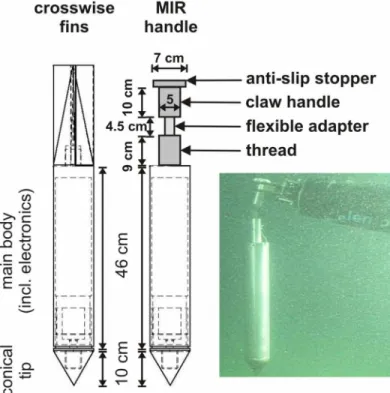
The dynamic penetrometer Nimrod (Fig. 3) has been in use since 2008 for in situ geotechnical characterization of seafloor sediments in difficult-to-access environments (e.g., close to offshore foundations, in energetic areas) and, in particular, for investigation of sediment remobilization processes such as subaqueous dune dynamics or scouring of the foundations of offshore wind energy converters (Stark et al. 2009). It has an approximately streamlined shape with three optional tip
geometries (cone, hemisphere, cylinder), a mass of 13-15 kg depending on the chosen tip, a length of 81 cm, and a diam-eter of 11 cm. During deployment, it falls nearly free (loose tether) through the water column and impacts the seafloor with velocities of on average 3-5 m s–1in water depths of about
30 m and on average 1 m s–1in water depths deeper than 140
m (Stark et al. 2009). Variations in impact velocity result from modifications of the penetrometer in terms of shape and weight (e.g., different tip geometry, enforcement of fins), dis-tance to bed, hydrodynamic conditions, and the tether used (Stark et al. 2009; Stark and Kopf 2011). The aluminum hull housing the electronics, the power supply, and the sensors (accelerometers, pressure transducer) was tested for maximum water depths of about 200 m. After impact, the probe pene-trates the seafloor between 4-30 cm in the case of sandy sedi-ments, and up to 3 m in the case of soft muddy sedisedi-ments,
depending on the particular grain size distribution, particle shapes, and state of consolidation. The probe measures decel-eration, pressure, and optionally, temperature with a sampling rate of 1 kHz. Single- and double integration of the measured deceleration allows estimation of penetration velocity and depth. The vertical resolution is about 1 cm depending on the penetration velocity (Stark et al. 2009). Approaches to esti-mate an equivalent of quasi-static bearing capacity or shear strength from the Nimrod’s deceleration results were described by Flaim et al. (2011) and Stark et al. (2011). However, it was shown that the deceleration profiles of dynamic penetrome-ters, which are fully decoupled from the working platform during deployment, are sufficient for characterizing physical and geotechnical behavior of the seafloor in the case of mod-erately varying impact velocities (Stoll and Akal 1999; Stark and Wever 2009).
Fig. 1.Overview over Lake Geneva, Switzerland. Vent and bise are the local names for predominant winds over the lake. Top: Zoom into Vidy Bay show-ing the MIR 2 transects from 16 Aug 2011 (red). Right: Zoom into the Rhône Delta multibeam bathymetric map (Sastre et al. 2010) showshow-ing the MIR 1 transects from 12 Aug 2011 (red).
In 2009, Nimrod was deployed from a submersed point of release by divers to target fine-scale bedforms on the conti-nental shelf off the Coromandel region, New Zealand (Stark et al. 2012). Following this experience, the Nimrod deploy-ment strategy using the MIR submersibles in Lake Geneva focused on using the robotic arm and claw of the MIRs for release and recovery. There are mainly two issues preventing the use of Nimrod in its standard configuration (Fig. 3), where the robotic claw would grasp either the main body or the tail. First, the closing-force of the claw is not monitored and could damage the aluminum housing of the main body. Second, complete embedding of the main body during impact was expected due to the soft and fine sediments at the lake bot-tom. Then, the exposed surface area of the main body would be limited during recovery. Deformation of the Nimrod is likely if grasped by the claw at its tail, and a stable grip can-not be assured. Therefore, a handle was designed that replaced the tail and allowed a reliable grip by the MIR’s robotic claw, thus minimizing the risk of damage (Fig. 3). The handle consists of three parts (Fig. 3): (i) an aluminum tube threaded on the main body, (ii) an aluminum tube with anti-slip stopper that can be grabbed, held, and released by the MIR claw, and (iii) a flexible connection between the two aforementioned tubes, allowing the penetrometer to find its vertical position before release even if the claw does not hold the handle perfectly vertically (Fig. 3). This configuration was used for both MIR dives in Lake Geneva.
Fig. 2.A) One of the MIR submersibles on the barge in Lake Geneva. B) MIR 1 prepared for the survey on 12 Aug 2011. One of the baskets was loaded with sediment coring tubes (left) and the other one carried Nimrod. Fixed pieces of wood secured Nimrod in the shown position to enable easy access by the robotic claw. During transit, the baskets were shifted further under the main body of the MIR. The video camera is attached to the portside robotic arm. C) Starboard robotic arm of MIR 1, which was used for deployment and recovery of Nimrod.
Fig. 3.Left: Technical draft of the dynamic penetrometer Nimrod with conical tip. Center: Nimrod configuration with MIR handle instead of the standard tail with crosswise fins. Right: Picture of Nimrod suspended from the MIR’s robotic arm.
Before the dives, Nimrod was placed in the portside front basket of the MIR, so that it rested on its tip with the handle protruding from the basket (Fig. 2). Wooden rails were mounted to keep the penetrometer from rolling or slipping in the basket. This setup allowed the MIR’s starboard robotic arm and claw to approach and grab the penetrometer handle, while following the movements with the camera attached to the portside robotic arm.
During transit the penetrometer remained in the basket, which was shifted further under the MIR’s main body. This ensured the secure transport of the instrument. For deploy-ment, the MIR was positioned on the lakebed for stability. Then, the portside basket with Nimrod was moved to its front position, and the pilot took hold of the Nimrod handle using the starboard robotic arm and claw. Nimrod was lifted out of the basket and above the targeted deployment position. To ensure the safe operation of the device from the submersible, it was essential not to hit or slide along the MIR during posi-tioning of the penetrometer, and for quality of the data, it was important to lift Nimrod securely above the lake bottom. The MIRs do not offer a measurement of claw-lifting height, and the resolution of the Nimrod’s pressure transducer is not suffi-cient to determine variations of less than a meter in water depth. Thus, the deployment height above bottom was esti-mated from visual observations. At the deployment position, the penetrometer was heaved 1-2 m above the lake bottom. The maximum height feasible with the robotic arm was 2 m. This strategy was sufficient to reproduce homogeneous impact velocities of 2.8-3.2 m s–1for 14 of 15 deployments. All
Nim-rod deployments from the MIRs were carried out without
attached tethers to avoid the risk of entanglement. First,
Nim-rod deployments were released from a height of about 1 m
above the lake bottom to test the maximum penetration depth of the penetrometer into the soft lake bottom, and to avoid the risk of subsequent problems for recovery. To mini-mize this risk, a float was attached to the penetrometer during the first deployment. This float would have helped during recoveries in the case of penetration depths ranging from 80-100 cm. The float’s leash length was ~ 30 cm to reduce the risk of entanglement.
On 12 August 2011, Nimrod measurements were carried out from MIR1 in the proximal areas of canyon C5 (Sastre et al. 2010) in the Rhône Delta (Fig. 1). Two measurement sites were located at the canyon floor, two at the northern levee struc-ture and one off the levee. Water depths in this area ranged between 80-110 m. C5 has not been active since the Vieux-Rhône river correction in the 19th century (Sastre et al. 2010), although turbidite deposits in the recent sediments suggest underflow processes during extreme flood events in the 20th century. At each of the five positions, Nimrod was dropped 2-3-times with 0.5-1 m horizontal distance between successive positions, and a short sediment core (~30 cm) was taken for groundtruthing. On 16 August 2011, a Nimrod survey was accomplished in Vidy Bay (Fig. 1) using MIR2. Two positions
were surveyed. The first site in a water depth of ~ 63 m was characterized by small-scale pillow-hollow structures (Vernet 1966; Brandl et al. 1993). Here, we aimed for two crests and two troughs of the structures located in the area within the reach of the robotic arm of the MIR resting in position 46°30.38′N and 6°35.19′E. The second position was closer to the lake-shore in a water depth of ~ 27 m at 46°30.75′N and 6°35.19′E, and was devoid of aforementioned lake bottom structures.
Assessment
A vertical free-fall was achieved if no disturbances occurred during release (Fig. 4). Such disturbances occurred during the first test deployments. They were caused by the attached float or by the anti-slip stopper. First, we observed that the float eas-ily got entangled with the claw after release. Second, when the claw held the handle vertically, the claw did not open suffi-ciently quickly to let the anti-slip stopper slide through with-out disturbance. These problems were solved after detaching the float, and ensuring a tilted claw position during release. After a few test deployments that showed penetration depths ~ 70 cm, it was justifiable to deploy the dynamic penetrometer without the float. Concerning the claw position, the flexible adapter between the threaded tube and the handle tube (Fig. 3) allowed vertical adjustment by gravity, although the claw held the handle at an angle or even horizontally. The deployment height was kept between 1-2 m. This height was sufficient to reach impact velocities ranging between 2.8-3.8 ± 0.5 m s–1(on
average 3.0 m s–1), and penetration depths of 27-40 ± 1 cm (on
average 30 cm) in the Rhône Delta and 70-81 ± 1 cm (on aver-age 74 cm) in Vidy Bay (Table 1). Recovery was not problematic for penetration depths of up to 80 cm. However, it can be assumed that deeper penetrations might have led to problems as the handle would then be significantly embedded.
The monitored maximum deceleration as well as the corre-sponding deceleration profile with depth (Fig. 5) gave repro-ducible results for repeated deployments at each position (Table 1), and hence, prove that the results are reliable. The measurements were not carried out at exactly the same posi-tion because the sediment surface and texture became highly disturbed by the penetration of the instrument. Thus, the reproducibility of the deceleration results suggests spatially homogeneous sediments at penetration depths of about 30 cm for a spatial range of at least 0.5-1 m in the case of the Rhône Delta. Similarly, homogeneous geotechnical signatures were found at penetration depths of about 74 cm in Vidy Bay. For the latter, the geotechnical signature of the sediment top-layer differed between pillows and hollows, but neither the water depth nor the pillow-hollow structures seemed to have an impact on these properties at a sediment depth in excess of about 20 cm.
Significant differences between the Rhône Delta and Vidy Bay were noted (Table 1, Fig. 5). In the Rhône Delta, maxi-mum decelerations of 2.3-2.8 ± 0.1 g were recorded at
pene-tration depths of only about 30 cm, whereas in Vidy Bay, max-imum decelerations remained < 1 ± 0.1 g down to penetration depths of about 74 cm. Thus, the sediments in Vidy Bay are significantly softer in the uppermost meter of the lake bottom than in the proximal areas of canyon C5 and in the Rhône Delta. According to Nimrod surveys in other regions, decelera-tion values < 1 g after impacts with about 3 m s–1correspond
to very soft and poorly consolidated fine-grained sediments or mud layers reworked by dynamic sediment processes. On the other hand, a maximum deceleration of 2-5 g after impacts with about 3 m s–1can often be associated with normally
con-solidated muddy to silty sediments (Stark et al. 2009). Generally, discontinuities in sediment strength can be caused by different sediment types (e.g., a sand layer in
Table 1.
Nimrod results from the surveys using MIR1 in the Rhône Delta on 12 Aug 2011 and from MIR2 in Vidy Bay on 16 Aug 2011.Deceleration (here: maximum deceleration during penetration) was measured using MEMS accelerometers (precision ± 0.1 g). The impact velocity and the penetration depth were determined by single and double integration of the deceleration, respectively. Possible stratification and resulting top layer thickness was estimated from the deceleration profiles and double checked after consideration of changes in penetration velocity and penetration surface area (Stark et al. 2011). The water depth was estimated by the MIR’s on-board sensors, whereas the hydrostatic pressure corresponded to the results of Nimrod’s pressure transducer at the starting point of the pen-etration process. The excess pore pressure values equal the difference between the maximum pressure value observed during penetra-tion and the hydrostatic pressure at the measurement depth.
Water Penetration Impact Top layer Hydrostatic Excess pore Position depth (m) depth (cm) velocity (m s–1) Deceleration (g) thickness (cm) pressure (kPa) pressure (kPa)
Rhône-1 100 33 3.0 2.3 11 1010 7 Rhône-1 100 31 2.8 2.2 10 1008 11 Rhône-2 103 Rhône-2 103 27 3.0 2.9 0 1030 20 Rhône-3 99 29 2.9 2.6 0 995 9 Rhône-3 99 31 3.2 2.4 0 991 11 Rhône-4 84 29 3.2 2.8 6 850 11 Rhône-4 84 27 3.1 2.8 6 850 12 Rhône-5 78 27 3.1 2.5 6 795 17 Rhône-5 78 40 3.8 2.7 5 795 16 Vidy-1-crest-1 63 70 3.0 0.6 0 617 5 Vidy-1-crest-2 63 70 2.9 0.8 0 610 4 Vidy-1-trough-1 63 70 2.8 0.9 5 617 –2 Vidy-1-trough-2 63 74 2.8 0.8 14 614 –1 Vidy-2 27 80 2.8 0.7 0 270 0 Vidy-2 27 80 3.2 0.8 0 275 –3
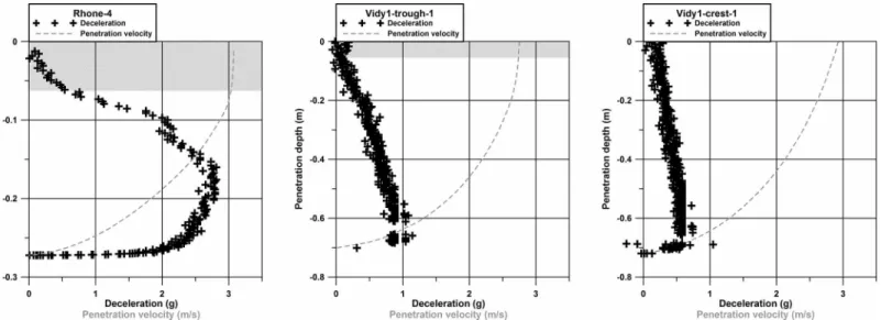
Fig. 5.Examples of deceleration–depth (crosses) and velocity–depth (gray dashed lines) profiles recorded using Nimrod at the C5 canyon floor in the Rhône Delta (left), in a trough of a pillow-hollow structure of Vidy Bay (center) and at a crest of the same structures (right). At position 4 in the Rhône Delta (left) a maximum deceleration of about 2.8 g and a penetration depth of about 27 cm was reached. The impact velocity was about 3.2 m s–1, and
a very soft top layer of about 6 cm thickness can be recognized. In Vidy Bay, the maximum deceleration was 0.6-0.9 g, and the penetration depth about 70 cm. The impact velocity was 2.8-3 m s–1. In the trough, the lowest deceleration, and thus, sediment strength was profiled underneath an
approxi-mately 5 cm thick superficial layer, whereas the profile measured at the crest displayed a homogeneous increase of deceleration with depth. Due to sig-nificantly larger penetration depths, the scaling along the y-axis differs for the data from the Rhône Delta (left) compared with the data from Vidy Bay (center and right).
dominantly clayey material), geochemical or biological processes (especially at the sediment surface), or sediment remobilization processes. Stratification is an important aspect of the geotechnical characterization of the surveyed positions. Eight of the deceleration profiles (four positions) showed an inhomogeneous increase in deceleration and, thus, sediment strength with depth, indicating stratification in terms of strength (Table 1, Fig. 5). In most cases, very soft top layers were found over a stiffer substratum (Fig. 5, left). On the con-trary, in troughs of the pillow-hollow structures in Vidy Bay, the minimum in sediment resistance was located a few cen-timeters below the sediment surface leaving a slightly more resistant surface layer on top of a very soft interface layer below which lies a stiffer substrate (Fig. 5, center). The troughs of the pillow-hollow structures showed significant variations in top layer thickness (trough 1: 5 cm, trough 2: 14 cm), whereas other position groups showed consistent stratifica-tion patterns (deviastratifica-tions < 1 cm). Decelerastratifica-tion profiles indi-cate a homogeneous state of consolidation (excluding the sur-face layer in the troughs). A difference in the gradient of deceleration versus penetration depth can be noted between crests and troughs.
The pressure transducer recorded hydrostatic pressure (± 5 kPa). The measured value just before impact matched well the water depths monitored by the MIRs (Table 1). Deviations were < 2 m, which might be explained by the position of the MIR’s hydrostatic pressure transducer being ~ 1.8 m above the bottom of the submersible.
During penetration of the probe, the pressure recording can be used to estimate excess pore pressure. However, with an uncertainty of ± 5 kPa only trends of excess pore pressure can be observed. Additionally, the location of the pressure trans-ducer inlets behind the conical tip leads to a 10 cm layback with regard to the position of the penetrometer tip. Nevertheless, in the Rhône Delta excess pore pressures were estimated to range between 10-23 ± 5 kPa. Variations were in good agreement with the trends of deceleration, and consequently, the trends of sed-iment strength. In Vidy Bay, excess pore pressures were between 11-12 ± 5 kPa in the crests of the pillow-hollow structures, but only 5-6 ± 5 kPa in the troughs. The latter correlated with the estimates from the shallower position (no pillow-hollow struc-tures) which range between 5-8 ± 5 kPa (Tab. I).
Discussion
The replacement of the cross-finned tail of the dynamic penetrometer Nimrod by a handle allowed rapid and simple deployments of the probe from the MIR submersibles with a very high spatial precision. Pillow-hollow structures (about 50 cm in width) were successfully targeted at their crests and troughs. Release from only 1-2 m height above the lakebed ensured approximately homogeneous impact velocities of about 3 m s–1, which is sufficient to characterize sediment
strength (Stark et al. 2009). During these surveys, penetration depths reached up to 40 cm in the Rhône Delta, and up to 80
cm in Vidy Bay. In the current configuration, penetration depths greater than 80 cm would lead to difficulties during recovery as the probe would be entirely embedded. Conse-quently, it is recommended to realize test drops with a leash in the survey area to determine the penetration depth from a range of possible release heights prior to the main survey. Dur-ing the survey, it is preferable to remove the leash to avoid possible entanglement during deployments.
The deceleration is measured by a setup of five micro-electromechanicalsystems (MEMS) accelerometers covering ranges from ± 1.7 g to ± 250 g, which ensure accurate record-ings of deceleration for soft to hard impacts (± 0.1 g for soft impacts). Comparison of the different accelerometer record-ings makes it possible to detect defects and errors of one accelerometer immediately, and the three-dimensional com-ponents of two of the MEMS accelerometers make it possible to check on the vertical adjustment of the penetrometer. Dur-ing the surveys, raw deceleration data confirmed straight impacts and correct readings of all accelerometers, allowing the assumption that the deceleration readings have an accu-racy of ± 0.1 g in accordance to the accuaccu-racy of the accelerom-eters.
Impact velocities ranged mainly between 2.8-3.2 m s–1(14
of 15 deployments) despite variations of deployment height above bottom in the range of 1-2 m, suggesting that the impact velocities were homogeneous. Furthermore, in the case of the deployment Rhône-5 during which an impact velocity of 3.8 m s–1was reached, the observed deceleration profile was
consistent with previous deployments in the Rhône area. This is in agreement with other dynamic penetrometer studies, where variations of impact velocity of ~ 1 m s–1still allowed a
comparison of the deceleration signatures (Stark and Wever 2009; Stark et al. 2009). Therefore, a geotechnical classifica-tion of the sediment using the deceleraclassifica-tion profiles and max-imum values is justified (Stoll and Akal 1999; Stark and Wever 2009; Stark et al. 2009). This can be confirmed by estimating an equivalent of quasi-static bearing capacity (Stark et al. 2011) leading to similar trends (estimate of quasi-static bear-ing capacity for a constant penetration velocity of 2 cm s–1:
Rhône Delta 2.4-3.4 ± 0.5 kPa, Vidy Bay 0.9-1.3 ± 0.2 kPa). The higher sediment resistance in the Rhône Delta can be explained by silty sediments that were found in sediment cores retrieved at the same positions as the Nimrod deploy-ments (averaged shear strength using a vane shear device ≈ 3.7 kPa), whereas in Vidy Bay fine sediments are expected (Pardos et al. 2004).
Stratification was found in the deceleration profiles of posi-tion 1 (top layer about 10 cm thick) and at posiposi-tions 4 and 5 (top layer about 6 cm thick) in the Rhône Delta showing a very soft layer on top of a stiffer substratum. This is a typical feature hinting at recent sediment remobilization processes (Stark and Kopf 2011). Although only C8, as well as C6 and C7 occasionally, are considered currently active canyons, ripples, and dunes observed during the MIR dives in the nearby
sub-marine canyon C5 suggest ongoing sediment remobilization processes in this area as well, supporting the hypothesis of recent underflow processes at positions 1, 4, and 5 in the Rhône Delta. Ongoing research aims at modeling and re-con-structing past, present, and future sediment dynamics in the Rhône Delta. A more extensive geotechnical survey conducted with Nimrod will be coupled with observation and numerical simulations of the hydrology and sediment dynamics in the delta. Prior field studies have documented the occurrence of energetic density currents in the active canyon (Lambert and Giovanoli 1988) and the dispersal of the interflow throughout the delta (Giovanoli 1990). The relative importance of these processes, the associated spatial and temporal variability of sediment fluxes and the resulting pattern of sediment deposi-tion in the Rhône Delta are not fully understood.
Our geotechnical measurements in Vidy Bay can be com-pared with results from sedimentological studies using radioisotopic, chemical, and microbial data. Dominik et al. (1992) described laminated short cores recovered from areas exhibiting pillow-hollow structures. These authors reported the same sequences in crests and troughs after consideration of a hiatus in the troughs where a section of the overlying sed-iment has been eroded. Adjacent troughs show large fluctua-tions in the thickness of the missing sediment and asyn-chrony of the erosion events (Dominik et al. 1992). The stratigraphic similarity below the discontinuity in sedimenta-tion is consistent with the observed overall homogeneity in the geotechnical properties beyond a sediment depth in the order of 20 cm.
The change in sediment strength between the top layer and the underlying substrate measured with Nimrod in troughs could correspond to the redox transition zone that Brandl et al. (1993) located a few centimeters below the sediment sur-face in troughs and at the sursur-face in crests. Furthermore, the observation that crest sediment is less compact and contains the bulk of organic detritus compared with the trough sedi-ment (Brandl, et al. 1993) is consistent with the subtle softness of crest sediment relative to trough sediment and with the observation of gas release from the lakebed during penetration of the Nimrod into the troughs. Gas is known to potentially modify the geotechnical properties of seabed and lakebed sed-iments (Sultan et al. 2004). The formation mechanism for the pillow-hollows and other lakebed structures is unclear at pres-ent. Should gas expulsion play a role of the generation of the lake-bottom morphology, gas would also probably contribute to the differences in geotechnical characteristics between crests and troughs. However, more in situ tests, in particular, focusing on excess pore pressure complemented by sediment coring, are required to draw conclusions with regard to the impact of gas on the geotechnical characteristics in Vidy Bay. The stratification observed in the troughs suggests rework-ing of the surficial sediment. The almost vertical slope of the deceleration profile is indicative of weakly consolidated sedi-ment in the surficial layer, consistent with troughs being
zones of sediment deposition. The bioturbation activity of Burbot fish in the troughs, repeatedly observed by divers in submersibles during this and prior campaigns, supports the hypothesis that this bottom-dwelling fish may be partly responsible for the maintenance of the pillow-hollow struc-tures (Vernet 1966; Dominik et al. 1992; Brandl et al. 1993). Random changes in the intensity and frequency of the fish activity from one structure to the next might explain the vari-ability in top layer thickness of the troughs. The mechanism of the formation and maintenance of these structures is uncer-tain and the subject of current investigations where the
Nim-rod results will be exploited.
The pressure transducer results estimated correct water depths and allowed the observation of excess pore pressure trends. However, for more detailed pore pressure studies, an uncertainty of ± 5 kPa is insufficient.
Comments and recommendations
After deploying the dynamic penetrometer Nimrod from the MIR submersibles during two surveys in August 2011 in Lake Geneva, the following statements can be made regarding the deployment of dynamic penetrometers from manned sub-mersibles:
Exchanging the cross-finned tail of the Nimrod penetrome-ter with a handle suitable for the MIR robotic claw allowed a rapid and simple deployment and recovery of the probe from the MIRs. In the current configuration, deployments could be carried out down to water depths of about 200 m (current depth-rating of Nimrod) and penetration depths up to about 80 cm.
Deployments should be realized without a safety leash to ensure the retrieval of the probe as this leash might get entan-gled with the robotic arm/claw. However, test drops with a leash should be carried out first to estimate the maximum penetration depth, especially in the case of soft sediments. A cotton leash with a float was easily detached by the second robotic arm of the MIR.
The characterization and classification of sediment strength was possible from the deceleration profiles due to homogeneous impact velocities. The latter was achieved by a release height ranging from 1-2 m and a stable position of the MIR on the lake bottom during deployments.
Stratification was observed. These data will be used to investigate sediment remobilization processes further.
The surveys proved that a dynamic penetrometer can be adjusted to deployments from manned submersibles and is an important complement for investigations of the seafloor or lakebed. In addition, a high spatial precision can be achieved and fine-scaled structures can be targeted, which are impossi-ble with deployments from the water surface. Furthermore, the deployments (position, fall and penetration performance) can be directly observed and documented by the operator.
The presented modification of the dynamic penetrometer would also allow deployments from Remotely Operated
Vehi-cles (ROV), which are increasingly used for seafloor investiga-tions, especially in deep water environments.
Acknowledgments
This study was funded via the éLEMO project supported by the “Fondation pour L’Étude des Eaux du Léman.” The Nimrod penetrometer was provided by MARUM–University of Bre-men. The development of Nimrod was funded by the German Research Association (DFG). The authors would like to thank Flavio Comino (EPFL) for the design and construction of the handle, and Christian Zoellner (MARUM) for technical assis-tance with Nimrod. We are indebted to the MIR crew, and in particular, to the pilots Evgeny Chernyaev and Viktor Nis-cheta, the Sagrave crew, as well as to Serge Burdet and Corinne Hoerger (both EPFL) for support during the dives. Further-more, we acknowledge the help of Flavio Amselmetti (Eawag) during planning and management of the dives.
References
Ashley, G. M. 1990. Classification of large-scale subaqueous bedforms: A new look at an old problem. J. Sediment. Petrol. 60:160-172 [doi:10.2110/jsr.60.160].
Beard, R. 1981. A penetrometer for deep ocean seafloor explo-ration. Proceedings OCEANS’81 Conference [doi:10.1109/ OCEANS.1981.1151586].
Brandl, H., K. W. Hanselmann, and R. Bachofen. 1990. In situ stimulation of bacterial sulfate reduction in sulfate-limited freshwater lake sediments. Federation of European Microbi-ological Societies. Microbiol. Ecol. 74:21-32 [doi:10.1111/ j.1574-6968.1990.tb04048.x].
———, ———, ———, and J. Piccard. 1993. Small-scale patch-iness in the chemistry and microbiology of sediments in Lake Geneva, Switzerland. J. General Microbiol. 139:2271-2275 [doi:10.1099/00221287-139-9-2271].
Corella, J. P., and others. 2013. Sediment dynamics in the sub-aquatic channel of the Rhone delta (Lake Geneva, France/Switzerland). Aquat. Sci [doi:10.1007/s00027-013-0309-4].
Dominik, J., J. -L. Loizeau, B. Gallerini, J. Piccard, R. Monod, and J. -P. Vernet. 1989. Use of radionuclides in interpreting sedimentary records: An application to the pollution his-tory from the sediments with the “pillow-hollow” bottom morphology in Lake Geneva, p. 461-466. In Proceedings of the 7th International Conference on Heavy Metals in the Environment, Geneva, Switzerland. CEP Consultants. ———, ———, and D. Span. 1992. Radioisotopic evidence of
perturbations of recent sedimentary record in lakes: A word of caution for climate studies. Climate Dynamics 6:145-152
[doi:10.1007/BF00193526].
Downing, J. A., and L. C. Rath. 1988. Spatial patchiness in the lacustrine environment. Limnol. Oceanogr. 33:447-458
[doi:10.4319/lo.1988.33.3.0447].
Flaim, B. K., N. Stark, V. Moon, W. De Lange, T. Healy, and A. Kopf. 2011. Monitoring a dredged material disposal site on
the continental shelf using the dynamic penetrometer Nimrod, p. 628-641. In Proceedings of the Coastal Sedi-ments’11 Conference in Miami, USA.
Giovanoli, F. 1990. Horizontal transport and sedimentation by interflows and turbidity currents in Lake Geneva, p. 175-195. In Large lakes: Ecological structure and function. Springer Verlag [doi:10.1007/978-3-642-84077-7_9]. Inman, D. L., C. E. Nordstrom, and R. E. Flick. 1976. Currents
in submarine canyons: An air-sea-land interaction. Annu. Rev. Fluid Mech. 8:275-310 [doi:10.1146/annurev.fl.08. 010176.001423].
Lambert, A., and F. Giovanoli. 1988. Records of riverborne tur-bidity currents and interactions of slope failures in the Rhône delta of Lake Geneva. Limnol. Oceanogr. 33:458-468
[doi:10.4319/lo.1988.33.3.0458].
Lang, C. 1989. Effects of small-scale sedimentary patchiness on the distribution of tubificid and lumbricutid worms in Lake Geneva. Freshw. Biol. 21:477-481 [doi:10.1111/j.1365-2427.1989.tb01380.x].
Le Dantec, N., Y. Akhtman, D. Constantin, U. Lemmin, D. A. Barry, and O. Pizarro. 2013. Morphology of pillow-hollow and quilted-cover bedforms in Lake Geneva, Switzerland, p. 159-166. In V. Van Lancker and T. Garlan [eds.], MARID 2013, Fourth International Conference on Marine and River Dune Dynamics, Bruges, Belgium, April 15-16, 2013. Royal Belgian Institute of Natural Sciences and SHOM, VLIZ special publication number 65-Flanders Marine Institute (VLIZ).
Mosher, D. C., H. Christian, D. Cunningham, K. MacKillop, A. Furlong, and K. Jarett. 2007. The Harpoon free fall cone penetrometer for rapid offshore geotechnical assessment. In Proceedings of the Offshore Site Investigation and Geot-echnics, Confronting New Challenges and Sharing Knowl-edge, London, UK, Sept 11-13, 2007. Society of Underwater Technology document ID OSIG-07-195.
Mulhearn, P. J. 2003. Influences of penetrometer tip geometry on bearing strength estimates. Int. J. Offshore Polar Eng. 13:73-78.
Pardos, M., C. Benninghoff, L. F. de Alencastro, and W. Wildi. 2004. The impact of a sewage treatment plant’s effluent on sediment quality in a small bay in Lake Geneva (Switzer-land-France). Part 1: Spatial distribution of contaminants and the potential of biological impacts. Lakes Reserv. Res. Manage. 9:41-52 [doi:10.1111/j.1440-1770.2004.00233.x]. Poeckert, R. H., J. M. Preston, T. L. Miller, M. Meakin, R. B.
Hurst, and D. F. Loft. 1996. A comparison of seabed pen-etrometers, p. 459-470. In Proceedings of the TTCP Sub-group G Symposium Shallow Undersea Warfare, Halifax, Canada.
Sagalevitch, A. M. 1997. 10 year anniversary of deep manned submersibles MIR-1 and MIR-2, p. 59-65. In Proceedings of the OCEANS’97 Conference in Halifax, Canada
[doi:10.1109/OCEANS.1997.634336].
Amselmetti, and W. Wildi. 2010. Morphology and recent history of the Rhône River Delta in Lake Geneva. Swiss J. Geosci. 103:33-42 [doi:10.1007/s00015-010-0006-4]. Stark, N., and T. Wever. 2009. Unraveling subtle details of
eXpendable Bottom Penetrometer (XBP) deceleration pro-files. Geo-Mar. Lett. 29:39-45 [doi:10.1007/s00367-008-0119-1].
———, H. Hanff, and A. Kopf. 2009. Nimrod—A tool for rapid geotechnical characterization of surface sediments. Sea Technol. 50:10-14.
———, ———, C. Svenson, V. B. Ernstsen, A. Lefebvre, C. Win-ter, and A. Kopf. 2011. Coupled penetromeWin-ter, MBES and ADCP assessments of tidal variations in surface sediment layer characteristics along active subaqueous dunes, Danish Wadden Sea. Geo-Mar. Lett. 31:249-258 [doi:10.1007/ s00367-011-0230-6].
———, and A. Kopf. 2011. Geotechnical investigation of sedi-ment remobilization processes using a dynamic penetrom-eter, p. 1–9. In Proceedings of the OCEANS’11 Conference in Kona, USA.
———, G. Coco, K. R. Bryan, and A. Kopf. 2012. In-situ geot-echnical characterization of mixed-grain-size bedforms using a dynamic penetrometer. J. Sediment. Res. 82:540-544 [doi:10.2110/jsr.2012.45].
Stegmann, S., T. Moerz, and A. Kopf. 2006. Initial results of a new free fall-cone penetrometer (FF-CPT) for geotechnical
in-situ characterization of soft marine sediments. Norwe-gian J. Geol. 86:199-208.
———, and A. Kopf. 2007. Marine deep-water free-fall CPT measurements for landslide characterization off Crete, Greece (Eastern Mediterranean Sea), Part 1: A new 4000 m cone penetrometer. Submarine Mass movements and Their Consequences. Adv. Natural Technol. Hazards Res. 27:171-177 [doi:10.1007/978-1-4020-6512-5_18].
Stoll, R. D., and T. Akal. 1999. XBP-tool for rapid assessment of seabed sediment properties. Sea Technol. 40:47-51.
Sultan, N., P. Cochonat, J. -P. Foucher, and J. Mienert. 2004. Effect of gas hydrates melting on seafloor slope instability. Mar. Geol. 231:379-401 [doi:10.1016/j.margeo.2004.10. 015].
Vernet, J. P. 1966. Prise de vues sous-lacustres dans le Léman lors de plongees du mesoscaphe Auguste Piccard. Bulletin de la Société Vaudoise des Sciences Naturelles. 69:287-292. Yafrate, N., J. DeJong, D. DeGroot, and M. Randolph. 2009. Evaluation of remolded shear strength and sensitivity of soft clay using full flow penetrometers. J. Geotech. Geoen-viron. Eng. 135:1179-1190 [doi:10.1061/(ASCE)GT.1943-5606.0000037].
Submitted 22 December 2012 Revised 20 June 2013 Accepted 25 September 2013