Matthias Reinhardt, Martin Kreuzer, Thomas Geue,
Reiner Dahint, Matthias Ballauff, and Roland Steitz*
Poly-acrylic Acid Brushes and Adsorbed
Proteins
DOI 10.1515/zpch-2014-0540
Received May 27, 2014; accepted March 5, 2015
Abstract: Planar polyelectrolyte brushes are prepared by Langmuir–Schaefer
based grafting of perdeuterated (styrene)49-b-(acrylic acid)222block copolymer (dPS-b-PAA) to dPS pre-coated silicon supports with grafting density𝜎PAAfrom 0.07 to0.11 nm−2. The structure of the solvent-swollen brushes, i. e. the volume fraction profile of polymer segments,𝜙PAA, as a function of altitude𝑧from the grafting plane into the liquid phase is extracted from neutron reflectivity measure-ments. We find that for all cases investigated𝜙PAA(𝑧)resembles a Gaussian profile. Although very condensed, the PAA brushes can be loaded with bovine serum al-bumin (BSA). The integral amount of adsorbed BSA scales linearly with grafting density. We compare our𝑧-resolved volume fraction profile𝜙BSA(𝑧)of BSA on PAA brushes with existing literature on that system. It is found that a cross-over takes place in the adsorption scheme from ternary compressive, where proteins can ap-proach the grafting surface only by compressing the brush, to ternary insertive, where proteins enter the brush with only local perturbation of the concentration profile, as a function of𝑅P/𝐻max, where𝑅Pis the Stokes-Radius of the protein, and𝐻maxis the experimentally determined maximum height of the brush.
Keywords: Polyelectrolyte Brush, Protein, Adsorption, Neutron Reflectivity,
Solid-liquid Interface.
*Corresponding author: Roland Steitz, Helmholtz-Zentrum Berlin, Institute of Soft
Matter and Functional Materials, Hahn-Meitner-Platz 1, 14109 Berlin, Germany, e-mail: [email protected]
Matthias Reinhardt, Martin Kreuzer, Matthias Ballauff: Helmholtz-Zentrum Berlin, Institute of
Soft Matter and Functional Materials, Hahn-Meitner-Platz 1, 14109 Berlin, Germany
Thomas Geue: Paul Scherrer Institut, Laboratory for Neutron Scattering, 5210 Villigen,
Switzerland
Reiner Dahint: Ruprecht-Karls-Universität Heidelberg, Applied Physical Chemistry, Im
1 Introduction
Adsorption of proteins to surfaces is an ubiquitous phenomenon in daily life [1]. Therefore, the understanding, stimulation and control of protein adsorption is of broad academic and applied interest. Manipulation of adsorption might start by functionalizing surfaces and interfaces by grafting polymers to the underly-ing substrates thereby changunderly-ing surface chemistry and topography [2]. In par-ticular, solvent-swollen polymer brushes can provide a soft micro-environment for adsorbed proteins that prevents conformational and structural changes, thus maintaining protein function, or even enhances the activity of the immobilized species [1,3–8]. Dependent on polymer chemistry these brushes can further react to external stimuli which in turn can change their protein immobilization capac-ity. Most prominent is the effect of the ionic strength of the dispersing medium which can alter a brush system from protein adsorbing to protein repellant [9]. A widely studied model, and quantitatively analyzed for both spherical (SPB) and planar polyelectrolyte brushes (PPB), is the adsorption of bovine serum albumin (BSA) to polyacrylic acid (PAA) brushes [10–22]. Here, the amount of immobilized BSA depends on the external parameters pH, ionic strength and protein concen-tration of the aqueous liquid phase and, in addition, on the internal parameters grafting density and PAA chain length. In contrast to the external parameters, which are easily controlled and manipulated in the experiments, grafting density and PAA chain length are typically fixed. A variation of grafting density and chain length is only achieved in the course of the preparation of the brushes. Most “graft-ing from” methods start directly from the substrate by in-situ growth of the brush system by atom transfer radical polymerization (ATRP [23,24]). This way, how-ever, grafting density is not well controlled. For “grafting to” methods, in particu-lar when utilizing amphiphilic diblock-copolymers [25,26] that weakness can be overcome. In the latter case the grafting density of the resulting polymer brush is pre-adjusted by manipulating the precursor Langmuir layer in a well-defined and reproducible manner before transferring the brush by Langmuir–Schaefer tech-nique to solid support.
In this study we used the Langmuir–Schaefer technique to prepare PAA brushes with varied grafting density. The resulting systems were analyzed by X-ray reflectometry (XRR) in dried and neutron reflectometry (NR) in swollen state. Subsequently, BSA was adsorbed from solution to the solvent-swollen brushes at pH=6.1, i. e. above the isoelectric point of acrylic acid. We compare our findings with existing𝑧-resolved data on the same system, i. e. planar and spherical PAA-brushes and adsorbed BSA at comparable experimental condi-tions of grafting density, pH and temperature,𝑇[13,17,18]. We classify the
exper-imental results within the context of recent theories on protein adsorption [27,28] and brush structure [29].
2 Materials and methods
2.1 Materials
Disk-shaped silicon substrates (60 mmin diameter and10 mmin height) were supplied by Siliciumbearbeitung Holm (Tann/Ndb., Germany). Perdeuterated polystyrene (dPS; 𝑀w= 65400; PDI 1.02) was purchased from Polymer Stan-dard Service (Mainz, Germany). Diblock copolymer perdeuterated (styrene)49 -b-(acrylic acid)222(dPS-b-PAA;𝑀w = 21500; PDI 1.13) was bought from Polymer Source (Montreal, Canada).D2O(> 99.9%), Bovine serum albumin (BSA; catalog number A-6003) and all other chemicals (absolute puriss. p. a.) were from Sigma-Aldrich and used as received.
2.2 Sample preparation
The silicon wafers were cleaned for30 minin ethanol and subsequently rinsed in ultrapure water (Milli-Q, resistance> 18.2 MΩ cm). A thin film of dPS was de-posited on the substrates by spin-coating (spin-coater model 6708D, SCS, Indi-anapolis, Indiana, USA) using a10 mg/mlpolymer solution in toluene followed by subsequent annealing at120∘Cfor20 minin an desiccator filled with Ar. For preparation and transfer of the PAA brush10 mgof dPS-b-PAA was dissolved in
6 ml1,4-dioxane at60∘Cfor48 h. After addition of4 mltoluene the polymer so-lution with a concentration of1 mg/mlwas spread on the surface of a10 mM 2-(N-morpholino)ethanesulfonic acid (MES) buffer solution in a Langmuir trough (R&K, Potsdam, Germany) using a Hamilton syringe [25]. The pH value of the buffer was adjusted to 6.1 using NaOH. With movable barriers at a compression of
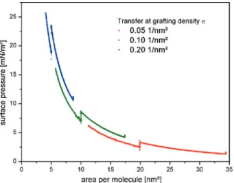
0.6 cm2/sthe grafting density of the dPS-b-PAA monolayer was adjusted to values of𝜎 = 0.05 nm−2, 0.1 nm−2, 0.2 nm−2for samples A1, A2 and A3, respectively (see also Figure1). The dPS-b-PAA monolayers were transferred to dPS pre-coated Si substrates applying the Langmuir–Schaefer technique by dipping the substrates onto the water surface of the Langmuir trough. The surface pressure at the trans-fer was monitored by the Wilhelmy plate pressure gauge of the Langmuir trough. Analysis of the surface loss area on the water surface at equal surface pressure lead to a transfer ratio of 1.3±0.1. After transfer, the brushes on solid support were
Figure 1: Surface pressure – area isotherm of free floating dPS-b-PAA monolayers at 20∘C and subphase pH 6.1. Positions of Langmuir–Schaefer transfers of the monolayers to
dPS-pre-coated silicon wafers at the three different grafting densities are indicated by respective drops of surface pressure in the isotherm at 20 nm2/molecule (red), 10 nm2/molecule (green) and 5 nm2/molecule (blue).
exposed to annealing at120∘Cfor15 minfollowed by rinsing with ultrapure wa-ter.
2.3 X-ray reflectivity
The X-ray reflectometer used was a home build 2-circle instrument with hori-zontal scattering geometry and a resolutionΔ𝑄 = 0.03 nm−1at a wavelength of
0.1541 nmgenerated by a Cu anode. Additional information on the instrument can be found elsewhere [30]. The X-ray raw data were footprint corrected and nor-malized to the intensity of the direct beam [31].
2.4 Neutron reflectivity
Neutron reflectivity (NR) measurements were performed at the time of flight re-flectometer AMOR at SINQ, Paul Scherrer Institut (PSI), Villigen, Switzerland [32]. A full reflectivity run consisted of measurements at incident angles 𝜃1 = 0.4∘,
𝜃2= 0.8 ∘and𝜃
3= 1.6
∘of the white beam on the samples planar solid-liquid inter-face through the silicon backing. Those measurements covered a Q-range of0.08
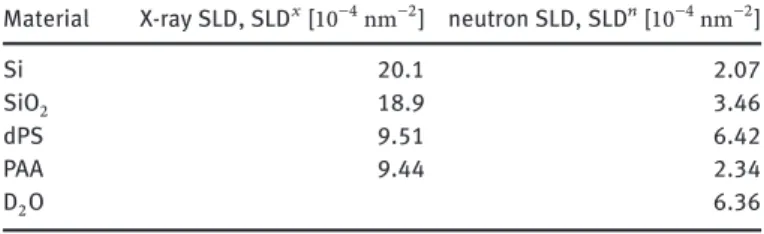
Table 1: Scattering length densities of materials and compounds used.
Material X-ray SLD, SLD𝑥[10−4nm−2] neutron SLD, SLD𝑛[10−4nm−2]
Si 20.1 2.07
SiO2 18.9 3.46
dPS 9.51 6.42
PAA 9.44 2.34
D2O 6.36
to1.74 nm−1in total consuming7 hof beam-time with a resolution ofΔ𝑄/𝑄 = 7% as defined by chopper system and slits. The sample cell was a high pressure cell for neutron reflectometry for pressures up to1000 bar, with which also measure-ments at elevated hydrostatic pressure can be performed. Detailed information on the sample cell can be found elsewhere [33]. All measurements were conducted against10 mMMES buffer solution inD2Oadjusted to pH=6.1 using NaOD. For adsorption of BSA to the PAA brushes, the samples (silicon/dPS/dPS-b-PAA) were incubated outside the sample cell with0.5 mg/ml BSA inD2OMES buffer so-lution for30 min. Before remounting, the samples were rinsed with pure buffer solution. All neutron reflectivity investigations were conducted at20∘Cwith the sample cell thermostatted by an external water bath. The raw data were normal-ized to the measured incident intensity spectra𝐼0Sithrough the silicon substrate mounted in the high pressure sample cell.
2.5 Data analysis
All reflectivity data were analyzed utilizing the Motofit software package [34], where, by the Abeles transfer matrix formalism [35], the reflectivity 𝑅fit(𝑄) of model scattering length density profiles SLD(𝑧) = ∑𝑖SLD𝑖(𝑧𝑖)of stratified me-dia [36] were calculated and compared with the experimental data,𝑅(𝑄).
In case of the XRR measurements on the brushes in dried state we subdi-vided the system in three parts – collapsed PAA brush layer, dPS (anchor and pre-coating) layer and silicon support from top to bottom. The nativeSiO2layer, sand-wiched between dPS layer and silicon support, was included in the roughness of the dPS-silicon interface. We found this a reasonable procedure as the scattering length densities ofSiO2and Si for X-rays are very close (see Table1). Attempts to fit that layer resulted in thickness smaller than roughness. The collapsed PAA brush against air was modeled by a series of𝑖slabs of fixed thickness𝑑𝑖= 0.7 nmand varied scattering length density SLD𝑖. A thickness of0.7 nmcorresponds to a𝑄𝑧
value of9 nm−1, which is 1.5 times larger than the maximum momentum trans-fer,𝑄max= 6 nm−1, probed in the conducted XRR measurements. Hence, artificial interferences in the calculated reflectivity curves used for fitting are avoided. The required number𝑖of slices representing the collapsed PAA brush layer were an outcome of the fitting process.
For the neutron measurements at the solid-liquid interface we subdivided the system into silicon backing, dPS (pre-coating+anchor) layer of the brush, PAA brush layer and bufferedD2Ofronting phase from top to bottom with respect to the incident beam. The nativeSiO2 layer, sandwiched between silicon support and the dPS pre-coating, was included in the roughness of the silicon-dPS inter-face. The dPS layer was represented by one box of thickness𝑑dPS as extracted from the preceeding X-ray measurements. The solvent-swollen PAA brush was di-vided into slices of2 nmthickness each with no inter-layer roughness. The re-ciprocal width of the chosen strata was twice the maximum momentum transfer
𝑄maxprobed experimentally. The required number𝑖of slices representing the PAA brush were outcome of the fitting process.
The neutron scattering length density of PAA was calculated to SLD𝑛PAA=
2.34 × 10⁻⁴nm−2at an acrylic acid monomer mass density of1.051 g/cm3[37] and the hydrogen of the acid group presumed exchanged by deuterium in contact with theD2Ofronting phase [37,38]. Starting at the grafting plane𝑧 = 0defining the dPS/PAA interface position the scattering length density SLD(𝑧)of any given slice of2 nmthickness of the solvent-swollen PAA brush inD2Ois given by the binary mixture of PAA andD2Oin that slice. Hence,
SLD(𝑧) = 𝜙PAA(𝑧)SLD𝑛PAA+ (1 − 𝜙PAA(𝑧))SLD𝑛D
2O (1) where 𝜙PAA(𝑧) = SLD(𝑧)−SLD 𝑛 D2O SLD𝑛PAA−SLD𝑛D 2O (2)
is the volume fraction profile of the PAA brush. The SLDs of all materials used in this work are summarized in Table1.
The statistical errors for a single fit within Motofit for all measurements con-ducted were smaller than5%in thickness and5%in scattering length density.
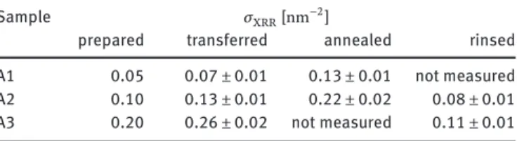
Table 2: Grafting densities 𝜎XRRfrom X-ray reflectometry measurements on samples A1–A3.
Sample 𝜎XRR[nm−2]
prepared transferred annealed rinsed A1 0.05 0.07 ± 0.01 0.13 ± 0.01 not measured A2 0.10 0.13 ± 0.01 0.22 ± 0.02 0.08 ± 0.01 A3 0.20 0.26 ± 0.02 not measured 0.11 ± 0.01
3 Results
3.1 Brushes at the solid-air interface
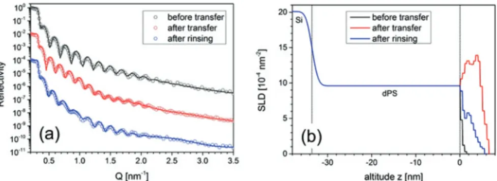
We controlled the preparation of the PAA brushes by X-ray reflectometry. Figure2
depicts the respective measurements on sample A2 conducted before and after transfer of the dPS-b-PAA Langmuir layer with the sample in a dried state. From the scattering length density profiles in Figure2b, the grafting density𝜎XRRwas extracted as 𝜎XRR = 1 𝑍𝑟𝑒 8 nm ∫ 0 nm (SLD(𝑧) −SLD(𝑧)) 𝑑𝑧 (3) where SLD(𝑧)and SLD(𝑧)are the fitted SLD profiles prior to and after LS transfer (and after rinsing),𝑍 = 11572is the total number of electrons of one dPS-B-PAA molecule and𝑟𝑒= 2.82 × 10⁻¹⁵mis the Thompson radius of the free electron. The extracted grafting densities are summarized in Table2. The values measured after the transfer of the brushes and the annealing step were found to be a factor of 2 larger than expected. Most likely with the transfer of the PAA brushes also excess water and additional polymer was transferred. The water evaporated in the course of the subsequent annealing step and left excess polymer behind. Only by extensive subsequent rinsing with ultra-pure water that material, i. e. buffer salt and any non-grafted polymer, was removed. The final grafting densities are gathered in the last column of Table2.
3.2 Brushes at the solid-liquid interface
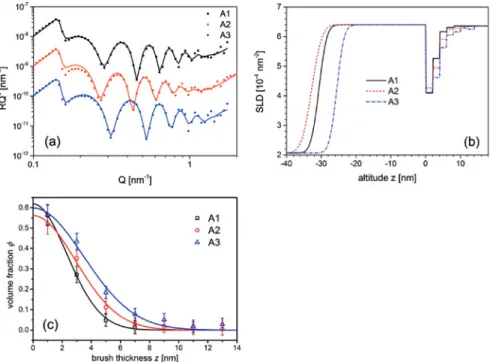
Figure3a shows NR data and fits for the re-swollen PAA brushes (A1–A3) against bufferedD2Osubphase at ambient conditions. All spectra exhibit characteristic Kiessig oscillations. The width of these oscillations depends on the thickness of
Figure 2: X-ray reflectivity (a) and extracted SLD profiles (b) of sample A2, transferred at
a pre-adjusted lateral density on the water surface of 𝜎 = 0.1 nm−2. Measurements were taken before transfer, i. e. on the dPS-precoating on silicon support (black), after transfer (red) and after rinsing (blue). Solid lines are fits to the data.
Table 3: Gaussian parameters of solvent-swollen brushes at the solid-liquid interface.
Sample 𝜎NR[nm−2] 𝜙0 𝐻0[nm]
A1 0.071 ± 0.007 0.62 ± 0.06 3.26 ± 0.07 A2 0.083 ± 0.008 0.56 ± 0.06 4.13 ± 0.14 A3 0.108 ± 0.010 0.60 ± 0.06 4.89 ± 0.24
the dPS sublayer while shape and height are related to the conformation of the protonated PAA brush. Figure3b shows the extracted SLD profiles for the PAA brushes and Figure3c gathers the resulting polymer brush volume fraction pro-files based on (2). These profiles exhibit a Gaussian shape described by the func-tion:
𝜙Gauss(𝑧) = 𝜙0𝑒−𝐻20𝑧2 (4) with volume fraction𝜙0at the grafting plane𝑧 = 0and thickness𝐻0. The grafting density is independently determined from the NR measurements by integration over the volume fraction profile𝜙PAA(𝑧):
𝜎NR= 1 𝑁𝜈PAA 18 nm ∫ 0 nm 𝜙PAA(𝑧)𝑑𝑧 (5) 𝜈PAA= 0.1137 nm
3is the acrylic acid monomer volume and𝑁 = 222is the degree of polymerization. The extracted brush parameters are compiled in Table3. Inter-estingly,𝜙0≈ 0.60 ± 0.05and is independent of the grafting density𝜎. Therefore,
Figure 3: Neutron reflectivity (a), extracted SLD profiles (b) and volume fraction profiles (c). Data
sets in (a) are offset by factors of 10 on the 𝑦-axis for clarity. Solid lines in (a) and (c) are fits to the data.
3.3 Protein adsorption
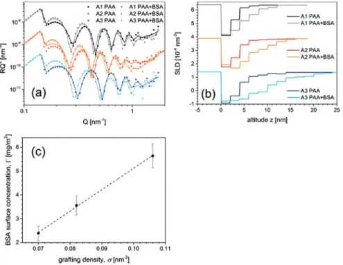
Figure4a shows the change of the NR data and fits after the adsorption of BSA to the PAA brushes. The shift of the Kiessig oscillations towards lower Q refers to an increase in brush thickness. This is a direct indication of a successful bind-ing of BSA proteins to the PAA brushes. The extracted SLD profiles are displayed in Figure4b. When BSA adsorbs to the PAA brush,D2Ois replaced by the pro-tein [13,18]. The neutron SLD of BSA, SLDBSA = 3.19 × 10⁻⁴nm−2[39], is lower than that ofD2O, resulting in a decreased SLD of the respective slab in the box model (cf. Figure4b). Integration over the difference of the SLD profiles before and after adsorption of BSA yields the adsorbed mass of BSA per surface area,𝛤BSA
𝛤BSA= MBSA VBSA ∫ z SLD∗(𝑧) −SLD(𝑧) SLD𝑛BSA−SLD𝑛D 2O 𝑑𝑧 (6)
where SLD(𝑧)and SLD∗(𝑧)are the extracted SLD profiles before and after pro-tein adsorption,𝑀 = 66 267 g/molis the molar mass and𝑉 = 48 574 cm3/mol (80.660 nm3/molecule) is the molar volume of BSA [39]. The calculated amount
Figure 4: (a): Neutron reflectivity data and fits for the PAA brushes A1–A3 before and after
adsorption of BSA. For visualization, respective data sets are offset by factors of 10 on the 𝑦-axis. (b): extracted SLD profiles of the PAA brushes A1–A3 before and after adsorption of BSA. For visualization, SLD data of A2 are offset by factors of −2.5 × 10⁻⁴nm−2and SLD data of A3 are offset by factors of −5 × 10⁻⁴nm−2on the 𝑦-axis. (c): Adsorbed amount of BSA over grafting density of samples A1–A3. 𝛤BSAscales linear with 𝜎.
of adsorbed protein per surface area for the three measured grafting densities is shown in Figure4c. A linear correlation between adsorbed amount of protein and grafting density is found.
4 Discussion
4.1 Brush structure
The preparation of brushes from dPS-b-PAA block-copolymer with varied grafting density worked well. In their solvent-swollen state at the solid-liquid interface all brushes exhibit a Gaussian shape with a maximum volume fraction𝜙0≈ 0.60at
the grafting plane. The Gaussian conformation is in qualitative agreement with theoretical self-consistent field (SCF) calculations [29,40,41] and experimental results [42,43]. PAA brushes belong to the class of weak annealed polyelectrolyte brushes for which Zhulina and Borisov derived a diagram of states [29]. For direct comparison, we transferred the physical parameters of our PAA brushes and the experimental boundary conditions into their reduced counterparts𝑡, 𝜈, 𝑢and𝛷 as given in Equations (38)–(41) of reference [29].
Reduced distance:𝑡 = 𝑏𝑧 = √3𝜋 2
8 𝑧
𝑎𝑁 (7)
Reduced polymer coverage:𝜈 = 4√2
3 𝑎𝑙B𝑁
2
𝑠 (8)
“Strength” of tethered polyacid:𝑢 = 16
3𝜋𝑎
2𝑙 B𝐾a𝑁
2 (9)
Relative salt content:𝛷 = 𝑐s
𝑐+ H
(10)
with𝑎, the length of an AA monomer in nm,𝑙B, the Bjerrum length of water in nm,𝑠, the grafting area per AA chain innm2,𝐾a, the dissociation constant of an AA monomer,𝑐S, the salt concentration inmol/land𝑐H+, the concentration of hydrogen ions inmol/l.
The monomer density profile𝑐AA(𝑧)of the acrylic acid (AA) brush segments is given by𝑐AA(𝑧) = 𝜙(𝑧)with the monomer volume𝑉AAof0.1137 nm3at a mass density of1.051 g/cm3. A single PAA polymer chain consists of𝑁 = 222monomer units with monomer length𝑎 ≈√6𝑉3
AA𝜋 ≈ 0.60 nm. The chains are grafted to the interface at a grafting density𝜎 = 1/𝑠, where𝑠is the grafting area per chain. For
𝜎 ≈ 0.1 nm−2, 𝑠 ≈ 10 nm2. The ionic strength of the10 mMmonovalent buffer is
𝐼 = 𝑐S= 10 mM. The concentration of hydrogen,𝑐 +
H, here the concentration of deu-terium ions,𝑐D+= 8 × 10⁻⁷mol/l, is set by the pH=6.1 of theD2Obuffer solution. The dissociation constant𝐾aof an AA monomer unit is given by its𝑝𝐾a, which is 4.35 for free acrylic acid monomers [44]. For polymerized acrylic acid the𝑝𝐾a shifts to higher values depending on salt concentration and degree of polymeriza-tion [45]. For the PAA brushes used in this work, the𝑝𝐾aapproximately equals the
𝑝𝐻value of the buffer solution and thus𝐾a= 8 × 10⁻⁷mol/l. The degree of ion-ization,𝛼𝑏, as determined by the mass action law𝛼𝑏/(1 − 𝛼𝑏)𝐾a𝑐D+equals 0.5. The Bjerrum length𝑙Bof water at25∘Cis0.71 nm.
With the experimentally specified set,𝑏 ≈ 0.014 nm−1, 𝜈 ≈ 6857, 𝑢 ≈ 0.017 and𝛷 = 7581, our PAA brushes are located in the osmotic annealing regime of the Zhulina-Borisov diagram of states (cf. Figure2in ref [29]). In this regime both poly-mer density and electrostatic potential vary substantially throughout the brush. The degree of ionization𝛼(𝑧)also varies and the value𝛼(0)at the grafting plane
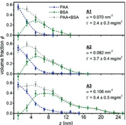
Figure 5: Volume fraction profiles of the conserved PAA brush and adsorbed BSA for samples
A1–A3. Smoothed lines are added to guide the eye.
differs significantly from the value𝛼(𝐻0) ≈ 𝛼𝑏for the chain ends stretched into the buffer solution. The theoretically calculated density profile for a PE brush in the osmotic annealing regime exhibits a characteristic Gaussian shape, which quali-tatively compares well with our experimental results.
4.2 Protein adsorption
4.2.1 Spatial distribution of BSA inside planar PAA brushes
Information on the integral amount of adsorbed proteins to polymer brushes is also available using lab-based methods such as ultra-filtration in case of spheri-cal polyelectrolyte brushes [12] or optical reflectometry [20] and surface plasmon resonance spectroscopy [21] in case of planar brushes. The advantage in utiliz-ing NR is in the extraction of information on the spatial distribution of bound proteins inside the polymer brushes. In this work, with only one scattering con-trast available, it was not possible to directly distinguish the𝑧-resolved mixing ratio of BSA, PAA andD2O. The profile for one of the components had to be fixed by an initial presumption. A first intuitive assumption is that there is no confor-mational change of the PAA brush upon loading with BSA in concordance with literature [13]. In this case of a conserved PAA brush the𝑧-resolved BSA volume fraction profile𝜙BSA(𝑧)can be extracted directly from the difference of the SLD
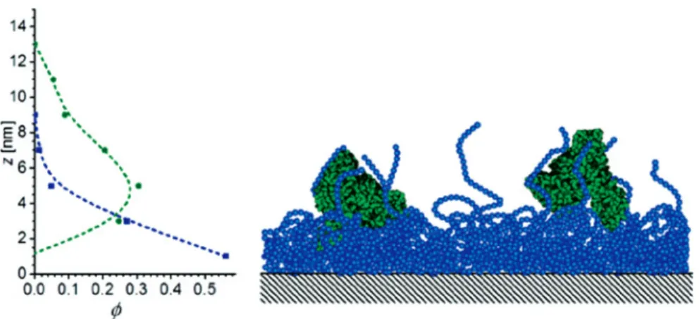
Figure 6: Schematic PAA and BSA volume fraction profiles for the conserved PAA brush model
based on the analysis of sample A1 (cf. also Figure3, bottom panel and Figure5).
profiles [13]: 𝜙BSA(𝑧) = SLD∗(𝑧) −SLD(𝑧) SLD𝑛BSA−SLD𝑛D 2O (11)
The extracted volume fraction profiles are shown in Figure5.
Within the error of the calculated profiles, the presumption of a conserved PAA brush results in a small negative adsorbed amount of protein close to the grafting plane of the brush. This result may indicate a potential stretching of the PAA brush with the adsorption. An assumed stretching of the PAA brush profile also changes the BSA volume fraction profile. This leads to a second model of a stretched PAA brush. At first, we will discuss the results for the conserved PAA brush (model I) followed by a debate of the results for the stretched PAA brush (model II).
4.2.2 Conserved PAA brush
The PAA brush adopts a very dense structure with PAA volume fractions𝜙 > 0.50 in the first2 nmslab near the grafting plane to the dPS sublayer. Dense polymer brushes are known to be resistant to protein adsorption [46]. Compared with our small brush, BSA is a relatively big molecule with lateral dimensions in the range of6–8 nm[39,47,48], with a mean (Stokes) radius𝑅P≈ 𝐻0.
Proteins that are large compared to the brush (𝑅P ≥ 𝐻𝑜)can approach the surface only by compression of the polymer brush [28,46,49]. The free energy penalty, associated with compression and compaction of the brush, favors
sec-Figure 7: Volume fraction profiles of stretched PAA brushes and adsorbed BSA. Smoothed lines
are added to guide the eye.
ondary adsorption of the protein at the outer surface of the brush [46]. The ex-tracted protein volume fraction profiles of Figure5directly support this model. Especially for the lowest and the intermediate grafting densities,𝜎 = 0.07and
0.082 nm−2, (sample A1 and A2) the volume fraction profile of adsorbed BSA de-scribes the adsorption of a BSA monolayer on top of the dense part of the PAA brush (Figure6). The volume fraction profile of BSA at highest brush grafting den-sity is more spread out in altitude𝑧and indicates adsorption of a second layer. In all cases investigated there is a pronounced separation of the centers of gravity,𝑐𝑚, of brush and adsorbed protein, ranging from an offsetΔ𝑐𝑚
𝑧 from 3.9 (A1) to6.7 nm (A3). The dangling PAA chain ends provide a soft environment for the adsorbed proteins, while the dense PAA inner layer screens the hydrophobic dPS sublayer and thus helps to preserve the native protein structure [10,11].
4.2.3 Stretched PAA brush
If the brush is stretched upon adsorption of BSA, an assumption has to be made to describe the resultant PAA brush profile. Our simple model II proposes a lin-ear stretching of the PAA brush by a factor based on the difference of its rms-thickness [50] before and after protein adsorption. Based on Figure5, middle panel, a mean stretching factor of1.9 ± 0.2was extracted this way, resulting in brushes that were extended to nearly twice their original length upon adsorption of BSA. Modifications were applied to the Gaussian PAA brush profiles with the
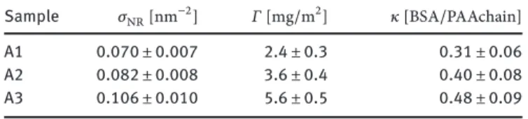
Table 4: Number 𝜅 of bound BSA molecules per PAA chain in relation to the grafting density 𝜎.
Sample 𝜎NR[nm−2] 𝛤 [mg/m2] 𝜅 [BSA/PAAchain]
A1 0.070 ± 0.007 2.4 ± 0.3 0.31 ± 0.06
A2 0.082 ± 0.008 3.6 ± 0.4 0.40 ± 0.08
A3 0.106 ± 0.010 5.6 ± 0.5 0.48 ± 0.09
respective stretching factors calculated individually for samples A1–A3. Figure7
shows the resulting volume fraction profiles. The profiles of adsorbed BSA follow the profiles of the PAA brush. A non-zero volume fraction of BSA is found directly at the grafting interface to the dPS sublayer, supporting primary adsorption.
4.2.4 Comparison of conserved and stretched PAA brush models after protein adsorption
Figures5and7show the volume fraction profiles of PAA and BSA after adsorp-tion on the presumpadsorp-tions of conserved and stretched PAA brushes, respectively. The main difference between the models is the adsorption of BSA either on top of the dense PAA screening layer in case of the conserved PAA brush or the penetra-tion of BSA into this layer down to the dPS grafting plane in case of the stretched PAA brush. Purely based on the available experimental data both models seem qualified in describing the adsorption of BSA. In case of the conserved brush, the non-physical negative amount of adsorbed BSA can be set to zero within error. The adsorption on top of the dense PAA screening layer is consistent with the protein resistance of dense polymer structures [46]. Also the preservation of the protein structure, as indicated by the volume fraction profile of BSA, supports zero ad-sorption next to the hydrophobic dPS sublayer, in-line with literature [10,11].
The adsorption on top of the planar PAA brush seems to be in contradiction to measurements on spherical polyelectrolyte brushes (SPB). There, BSA was found deep inside the PAA brush [16,17]. These results favor the extracted BSA density profiles based on the stretched PAA brush model. However, direct comparison of SPB brushes and the planar brushes in this work is not straightforward. The thick-ness of the spherical PAA brushes was larger than50 nmand thus 3–5 times big-ger than the maximum thickness of the planar PAA brushes used here. In a brush with a thickness of𝑡 > 50 nma dense2–3 nmthick screening (carpet) layer at the grafting plane is negligible. The diluted part of the spherical PAA brush ac-cessible to protein adsorption amounts to95%. For the smaller planar brushes in this work the dense screening or carpet layer covers up to30%of the total brush
thickness and thus directly affects the protein adsorption. Hence, the adsorption of BSA on top of dense, thin PAA brushes, as suggested by the model of the con-served brush, is not in contradiction to existing results on the adsorption of BSA inside thick spherical PAA brushes. Taken the protein resistance of dense polymer brushes into account, the conserved PAA brush model seems preferable over the model of the stretched brush.
Up to this point our comparison between the conserved and stretched brush model was exclusively based on the protein distribution with respect to the PAA brush profile, irrespective of the integral amount of bound BSA. With increasing grafting density𝜎the integral amount𝛤of adsorbed BSA also increases in a linear fashion (Figure5, bottom). The latter is not true for the ratio𝜅 = 𝛤/(𝜎⋅𝑚BSA)of the average number of bound BSA per PAA chain, where𝑚BSA = 1.1 × 10⁻¹⁹gis the mass of a single BSA molecule [39]. With increasing grafting density𝜎,𝜅increases in a non-linear fashion (see Table4).
If BSA can bind to any position inside the PAA brush, as is the case for the stretched PAA brush,𝜅is expected to be constant. In case of the conserved PAA brush, the dense PAA screening layer is not penetrated by BSA. Adsorbed proteins are found exclusively in the diluted outer part of the brush. With the completion of the screening layer, its relative contribution to the total brush thickness should decrease with increasing grafting density, i. e. further stretching. Thus,𝜅should converge to a plateau value in the long chain limit, where the contribution of the screening layer to the total brush length was negligible. Our experimental results gathered in Table4are in line with such expectation. Hence, also the extracted integral amount of adsorbed BSA proteins supports the model of the conserved PAA brush.
4.3 Comparison with literature
4.3.1 Relevant length scales
Following a very basic scheme, we can subdivide protein adsorption to polymer brushes into primary, secondary and ternary adsorption [27]. In case of primary adsorption the radius𝑅Pof the immobilized protein is smaller than the mean dis-tance between graft points of the polymer chains, i. e.𝑅P < 1/√𝜎, and the pro-tein adsorbs at the grafting plane. In case of secondary adsorption,𝑅Pis much larger than the mean distance between graft points, i. e.𝑅P≫ 1/√𝜎, and conse-quently, the protein is not to penetrate the brush and adsorbs at the outer surface. In case of matching quantities,𝑅P ≈ 1/√𝜎, we are in the ternary regime and the protein molecules adsorb to polymer segments within the brush. Halperin and
Figure 8: Stokes Radius 𝑅𝑃of BSA normalized on brush height 𝐻maxand plotted versus 𝐻max.
Here, 𝐻maxis the maximum height of the brush as read out from the experimental SLD profiles shown in the respective papers.
Kröger further differentiate the latter regime into strong and weak ternary adsorp-tion [28]. Due to the lack of specific binding sites, our system, PAA+BSA, is placed within the weak ternary adsorption regime. According to Halperin and Kröger that regime comes in two modes, namely ternary insertive, where small proteins with
𝑅P≪ 𝐻0enter the brush with only local perturbation of the concentration pro-file, and ternary compressive, where large proteins with𝑅P ≫ 𝐻0can approach the grafting surface only by compressing the brush of height𝐻0 (cf. Figure2in ref [28]).
In Figure8we list available data on the system PAA+BSA in accordance with the Halperin and Kröger criteria laid out above.
In this plot the condition of secondary adsorption is realized for𝑅P/𝐻max ≥
0.5, while ternary adsorption in insertive mode to primary adsorption is given for𝐻max→ ∞and thus𝑅P/𝐻max→ 0. Our system is located halfway between the endpoints. Consequently and as shown already in paragraph 4.2.1 from the z-resolved volume fraction profiles we are dealing here with the ternary adsorption of BSA to short PAA brushes in compressive mode. As the length𝐻maxof brushes increases the adsorption mode of BSA changes continuously until an experimen-tal endpoint is reached at𝑅P/𝐻max= 0.05for the spherical brushes in the work by Henzler et al. [17].
4.3.2 Scaling
Except for the spherical PAA brushes utilized by Henzler et al. [17], all brush sys-tems compared here are prepared by the grafting-to technique via Langmuir
pre-Figure 9: Experimentally determined brush height 𝐻maxversus degree of polymerization 𝑁 of the utilized PAA polymers.
Figure 10: Adsorbed amount of BSA on planar PAA-brushes at 𝜎 = 0.1 nm−2as a function of height 𝐻maxof the brushes at the solid-liquid interface.
cursors of PS-b-PAA block-copolymers. The latter brushes all come with an exper-imentally adjusted grafting density of0.1 nm−2and are exposed to an aqueous phase of pH 6–7 at room temperature. For the very reason one would expect the brush height𝐻maxof the investigated systems to scale with the degree of poly-merisaton𝑁of the PAA blocks, i. e.𝐻max∝ 𝑁. From Figure9 it becomes ob-vious that this simple scaling prediction is violated experimentally. On the best the height of the prepared brushes is independent of𝑁with a statistical average height𝐻̄maxof 20± 5 nmfor a statistical span of𝑁̄ of 220±48. The most positive conclusion one can draw here is that the variation in𝑁is simply too little to be effective, the most negative one is to state that there is at minimum one additional experimental parameter influencing the final brush height which is out of control. Such parameter could be an intermediate annealing step or intermediate drying
of the brushes. A broader data base, in particular with a much larger variation of
𝑁, is required to clarify this issue.
4.3.3 Adsorbed amount
The total adsorbed amount of BSA scales linearly with the grafting density of the PAA brush (Figure5, bottom) in line with an increasing number of binding sites per unit area and in line with results by optical reflectometry [20]. Figure10 de-picts the adsorbed amount of BSA on planar PAA brushes which can be compared directly. Interestingly the shortest brush seems to immobilize the largest amount of protein. The picture changes immediately when taking into account the fact that the adsorbed amount of protein also depends on the protein concentration of the aqueous reservoir [51,52]. Hollmann [18] and Czeslik [13] used bulk concen-trations,𝑐eq, of BSA, which were1/10of the one we used on this work, namely
0.05 mgBSA/ml (Hollmann 07, Czeslik 04) as compared to0.5 mgBSA/ml (this work). Hence, comparison of published data is not straight forward without cor-recting for𝑐eq, incubation time, incubation temperature and potentially further boundary conditions which have to be taken into consideration.
5 Summary and conclusions
Solvent-swollen planar PAA brushes at three different grafting densities were vestigated by neutron reflectivity at the solid-liquid interface before and after in-cubation with BSA at ambient conditions. The extracted Gaussian volume frac-tion profiles of the brushes are in line with theoretical predicfrac-tions for osmoti-cally annealed brushes. Differences are found for the detailed stretching of the brushes. These might be caused by additional interactions at the grafting plane. The experimentally observed increased density of PAA near the anchoring plane might originate from screening of the hydrophobic dPS sublayer from theD2O subphase. BSA adsorbs to the PAA brushes from solution. The adsorbed amount of protein scales linear with the grafting density of brushes. As for the distribu-tion of BSA within the PAA brushes, two different structural models are consid-ered: Model I presumes conservation of PAA brush structure upon BSA adsorp-tion, model II favors affine stretching of the brushes by a factor of 2. In model I the BSA molecules would not penetrate but were adsorbed at the surface of the brushes following a secondary adsorption scenario. On the contrary, in model II, BSA molecules would penetrate resulting in a homogenous distribution of protein
inside the brushes as was expected for weak ternary adsorption. From comparison with literature both on experimental systems and theory of protein adsorption to brushes we classify our case as weak ternary adsorption in compressive mode.
Acknowledgement: This work is based on experiments performed at the Swiss
spallation neutron source SINQ, Paul Scherrer Institut (PSI), Villigen, Switzer-land. The authors thank Helmholtz-Zentrum Berlin and Paul Scherrer Institut for financial support.
References
1. C. Czeslik, Chem. Unserer Zeit40 (2006) 238.
2. V. Papaefthimiou, R. Steitz, and G. H. Findenegg, Chem. Unserer Zeit42 (2008) 102.
3. C. Jeworrek, O. Hollmann, R. Steitz, R. Winter, and C. Czeslik, Biophys. J.96 (2009) 1115.
4. N. Ayres, Polymer Chem.1 (2010) 769.
5. A. Wittemann and M. Ballauff, Phys. Chem. Chem. Phys.8 (2006) 5269.
6. A. L. Becker, K. Henzler, N. Welsch, M. Ballauff, and O. Borisov, Curr. Opin. Colloid In.17
(2012) 90.
7. K. Henzler, B. Haupt, K. Lauterbach, A. Wittemann, O. Borisov, and M. Ballauff, J. Am Chem. Soc.132 (2010) 3159.
8. N. Welsch, A. Wittemann, and M. Ballauff, J. Phys. Chem. B113 (2009) 16039.
9. C. Czeslik, G. Jackler, T. Hazlett, E. Gratton, R. Steitz, A. Wittemann, and M. Ballauff, Phys. Chem. Chem. Phys.6 (2004) 5557.
10. C. Reichhart and C. Czeslik, Langmuir25 (2009) 1047.
11. A. Wittemann and M. Ballauff, Anal. Chem.76 (2004) 2813.
12. A. Wittemann, B. Haupt, and M. Ballauff, Phys. Chem. Chem. Phys.5 (2003) 1671.
13. C. Czeslik, G. Jackler, R. Steitz, and H. H. von Grunberg, J. Phys. Chem. B108 (2004) 13395.
14. A. Wittemann, B. Haupt, and M. Ballauff, Z. Phys. Chem.221 (2007) 113.
15. O. Hollmann and C. Czeslik, Langmuir22 (2006) 3300.
16. S. Rosenfeldt, A. Wittemann, M. Ballauff, E. Breininger, J. Bolze, and N. Dingenouts, Phys. Rev. E (2004) 70.
17. K. Henzler, S. Rosenfeldt, A. Wittemann, L. Harnau, S. Finet, T. Narayanan, and M. Ballauff, Phys. Rev. Lett.100 (2008) 158301.
18. O. Hollmann, T. Gutberlet, and C. Czeslik, Langmuir23 (2007) 1347.
19. J.H. Dai, Z. Y. Bao, L. Sun, S. U. Hong, G. L. Baker, and M. L. Bruening, Langmuir22 (2006)
4274.
20. W. M. de Vos, P. M. Biesheuvel, A. de Keizer, J. M. Kleijn, and M. A. C. Stuart, Langmuir24
(2008) 6575.
21. O. Hollmann, C. Reichhart, and C. Czeslik, Z. Phys. Chem.222 (2008) 205.
22. E. Bittrich, Rodenhausen KB, Eichhorn KJ, T. Hofmann, M. Schubert, M. Stamm, and P. Uhlmann, Biointerphases5 (2010) 1.
23. N. D. Treat, N. Ayres, S. G. Boyes, and W. J. A. Brittain, Macromolecules39 (2006) 26.
25. E. P. K. Currie, A. B. Sieval, M. Avena, H. Zuilhof, E. J. R. Sudholter, and M. A. C. Stuart, Langmuir15 (1999) 7116.
26. E. P. K. Currie, W. Norde, and M. A. C. Stuart, Adv. Colloid Interf. Sci.100 (2003) 205.
27. H. Kuroki, I. Tokarev, and S. Minko, Ann. Rev. Mater. Res.42 (2012) 343.
28. A. Halperin and M. Kroger, Langmuir25 (2009) 11621.
29. E. B. Zhulina and O. V. Borisov, Langmuir27 (2011) 10615.
30. J. R. Howse, R. Steitz, M. Pannek, P. Simon, D. W. Schubert, and G. H. Findenegg, Phys. Chem. Chem. Phys.3 (2001) 4044.
31. I. K. Voets, W. A. de Vos, B. Hofs, A. de Keizer, M. A. C. Stuart, R. Steitz, and D. Lott, J. Phys. Chem. B112 (2008) 6937.
32. M. Gupta, T. Gutberlet, J. Stahn, P. Keller, and D. Clemens, Pramana-J. Phys.63 (2004) 57.
33. M. Kreuzer, T. Kaltofen, R. Steitz, B. H. Zehnder, and R. Dahint, Rev. Sci. Instrum. (2011) 82.
34. N. Andrew, J. Phys.251 (2010) 012094.
35. O. S. Heavens, Optical Properties on Thin Solid Films Dover Publications, Incorporated, Mineola, N.Y. (U.S.) (1955).
36. M. Tolan and W. Press, Z. Krist.213 (1998) 319.
37. J. E. Mark, Polymer Data Handbook Oxford University Press, New York (1999). 38. V. F. Sears, Neutron News3 (1992) 26.
39. D. C. Carter and J. X. Ho, Adv. Protein Chem.45 (1994) 153.
40. R. R. Netz and M. Schick, Macromolecules31 (1998) 5105.
41. E. A. DiMarzio and F. L. McCrackin, J. Chem. Phys.43 (1965) 539.
42. A. Karim, S. K. Satija, J. F. Douglas, J. F. Ankner, and L. J. Fetters, Phys. Rev. Lett.73 (1994)
3407.
43. P. Auroy, Y. Mir, and L. Auvray, Phys. Rev. Lett.69 (1992) 93.
44. J. F. J. Dippy, S. R. C. Hughes, and A. Rozanski, J. Chem. Soc. (1959) 1441.
45. T. Miyajima, M. Mori, S. Ishiguro, K. H. Chung, and C. H. Moon, J. Colloid Interf. Sci.184
(1996) 279.
46. A. Halperin, Langmuir15 (1999) 2525.
47. M. L. Ferrer, R. Duchowicz, B. Carrasco, J. G. de la Torre, and A. U. Acuna, Biophys. J.80
(2001) 2422.
48. F. L. G. Flecha and V. Levi, Biochem. Mol. Biol. Edu.31 (2003) 319.
49. A. Halperin, G. Fragneto, A. Schollier, and M. Sferrazza, Langmuir23 (2007) 10603.
50. Y. V. Lyatskaya, F. A. M. Leermakers, G. J. Fleer, E. B. Zhulina, and T. M. Birshtein, Macro-molecules28 (1995) 3562.
51. A. Baszkin and W. Norde, Physical Chemistry of Biological Interfaces CRC Press, New York, Basel (1999).