Publisher’s version / Version de l'éditeur:
Vous avez des questions? Nous pouvons vous aider. Pour communiquer directement avec un auteur, consultez la première page de la revue dans laquelle son article a été publié afin de trouver ses coordonnées. Si vous n’arrivez pas à les repérer, communiquez avec nous à [email protected].
Questions? Contact the NRC Publications Archive team at
[email protected]. If you wish to email the authors directly, please see the first page of the publication for their contact information.
https://publications-cnrc.canada.ca/fra/droits
L’accès à ce site Web et l’utilisation de son contenu sont assujettis aux conditions présentées dans le site LISEZ CES CONDITIONS ATTENTIVEMENT AVANT D’UTILISER CE SITE WEB.
First AO4ELT conference - Adaptive Optics for Extremely Large Telescopes,
2010, pp. 1-6, 2010-02-24
READ THESE TERMS AND CONDITIONS CAREFULLY BEFORE USING THIS WEBSITE. https://nrc-publications.canada.ca/eng/copyright
NRC Publications Archive Record / Notice des Archives des publications du CNRC :
https://nrc-publications.canada.ca/eng/view/object/?id=e02fdbd2-0c42-4c1e-8659-c4a873427055
https://publications-cnrc.canada.ca/fra/voir/objet/?id=e02fdbd2-0c42-4c1e-8659-c4a873427055
NRC Publications Archive
Archives des publications du CNRC
This publication could be one of several versions: author’s original, accepted manuscript or the publisher’s version. / La version de cette publication peut être l’une des suivantes : la version prépublication de l’auteur, la version acceptée du manuscrit ou la version de l’éditeur.
For the publisher’s version, please access the DOI link below./ Pour consulter la version de l’éditeur, utilisez le lien DOI ci-dessous.
https://doi.org/10.1051/ao4elt/201002004
Access and use of this website and the material on it are subject to the Terms and Conditions set forth at
NFIRAOS - first light adaptive optics system for TMT
Herriot, Glen; Andersen, David; Atwood, Jennifer; Boyer, Corinne; Byrnes,
Peter; Conan, Rod; Ellerbroek, Brent; Gilles, Luc; Hickson, Paul; Jackson,
Kate; Lardière, Olivier; Véran, Jean-Pierre; Wang, Lianqi
NFIRAOS - first light adaptive optics system for TMT
Glen Herriot1,a, David Andersen1, Jennifer Atwood1, Corinne Boyer2, Peter Byrnes1, Rod Conan3, Brent Ellerbroek2, Luc Gilles2, Paul Hickson4, Kate Jackson2, Olivier Lardière3, Jean-Pierre Véran1, and Lianqi Wang2
1 NRC Herzberg Institute of Astrophysics, 5076 W. Saanich Rd., Victoria, BC, V9E 2E7, CANADA 2 TMT Observatory, 2632 E. Washington Blvd, Pasadena, CA, 91197, USA
3 AO Laboratory, Mech. Eng. Dept., UVic, PO Box 3055 STN CSC, Victoria, BC, V8W 3P6, CANADA 4 Dept. of Physics and Astronomy, 6224 Agricultural Rd., UBC, Vancouver, BC, V6T 1Z1, CANADA
Abstract. NFIRAOS, the TMT Observatory’s initial facility AO system will correct atmospheric turbu-lence with 50 per cent sky coverage at the galactic pole. It is a multi-conjugate AO system feeding science light from 0.8 to 2.5 microns wavelength to three near-IR client instruments. NFIRAOS is an order 60x60 system with two deformable mirrors optically conjugated to 0 and 11.2 km. Very low background is an important design driver: one DM is mounted on a tip/tilt platform to reduce surface count; the optics are cooled to – 30 C. NFIRAOS’ real time control uses six sodium laser wavefront sensors and up to three IR natural guide star tip/tilt and/or tip/tilt/focus sensors located within each client instrument. To compensate errors arising from the variability of the sodium layer, to which extremely large telescopes are more sensi-tive, NFIRAOS uses innovative algorithms coupled with a pair of Truth wavefront sensors that monitors a natural star at low bandwidth. For calibration, NFIRAOS includes simulators of both natural stars at infin-ity and laser guide stars at varying range distance. It also includes an IR acquisition camera, and a high-speed NGS WFS for operation without lasers.
1 Introduction
NFIRAOS (Narrow Field, Infrared Adaptive Optics System) is the first light laser guide star adaptive optics system for the Thirty Meter Telescope. It is a multi-conjugate (MCAO) system to improve sky coverage and image quality, planned to give performance equivalent to AO on current telescopes. The telescope structure supports NFIRAOS above the Nasmyth platform, and in turn NFIRAOS supports and feeds three client instruments located on the top bottom and side of NFIRAOS. The NFIRAOS optics are in a cooled box except for the laser guide star zoom optics and six wavefront sensors, which hang below the cooled box and operate at dome temperature. The electronics reside on the Nasmyth platform, 7 meters below the optical axis. To reduce risk, NFIRAOS is being designed using currently demonstrated technologies and architecture.
The NFIRAOS is being designed at the NRC Herzberg Institute of Astrophysics (HIA) in Victoria Canada and the team reports to the TMT project office.[2] The project scientist is Paul Hickson at the University of British Columbia in Vancouver. Performance modeling is carried out at the project office, at HIA and at the University of Victoria, where laboratory demonstrations of algorithms are also done.[8] The preliminary design review was held in last 2008, and we are currently updating the design, based on advice received.
2 Requirements
The top-level requirements for NFIRAOS flow down from the science-based requirements of the TMT Observatory. [1]
x 85 per cent throughput from 0.8 to 2.5 ȝm
x Thermal emission < 15 % of background from sky and telescope x 187 nm RMS wavefront error on-axis, and 191 nm on a 10” FoV
AOFOR ELT
x 50% enclosed energy within 160 mas pixels in K-band over a 2.3’ FoV x 50% sky coverage at the Galactic pole
x 2% differential photometry for a 2 minute exposure on a 30” FoV x 50 mas differential astrometry for a 100 s exposure on a 30” FoV x Astrometric Error falling as t-1/2 to a systematic floor of 10 ȝas x System available from standby within 10 minutes
x 5 minutes to acquire a new field x < 1 per cent unscheduled downtime
The sky coverage specification of 50% at the galactic pole is defined as the probability of having less than 2 mas residual tip tilt jitter.
3 NFIRAOS Architecture
To achieve high sky coverage, NFIRAOS’ design employs several strategies. First of all, six laser guide stars will be projected from behind the telescope secondary mirror.[5] As well, tip/tilt and focus measure-ments, which cannot be sensed by laser beacons, are done on near-infrared guide stars, which are generally more numerous and brighter in the infrared than in visible wavelengths. More importantly, NFIRAOS’ MCAO design, over a broad 2-arcminute field of view, sharpens these stars so that tip/tilt may be sensed more accurately for a given flux. The sensors are located within a client instruments in order to be close to the focal plane to also detect flexure. Three tip/tilt and focus sensors are required to sense field distortion and rotation. Each one of these on-instrument wavefront sensors is configurable to be a 2x2 Shack-Hartmann sensor, usually deployed on the brightest star in the field, while the other two are configured as simple imagers to sense tip/tilt. [3]
For good image quality over a wide field, NFIRAOS uses atmospheric tomography with six laser guide stars. This tomography[7] drives a pair of order 60x60 deformable mirrors conjugate to 0 and 11.2 km. This combination of tomography and multi-conjugate deformable mirrors corrects wavefront error over a wider field of view compared with classical AO. Since the higher conjugate-altitude mirror is offset by half an actuator pitch, on-axis performance is also enhanced.
To achieve good optical throughput and low thermal background, optical surface count is minimized and the optics are cooled to -30 °C [4]. One DM, conjugate to 0 km, is mounted on a tip/tilt stage, again to re-duce surfaces.
Errors in centroiding each laser wavefront sensor subaperture may be caused by variations in seeing and in the sodium layer.[9] The centroiding gains are sensed by dithering the laser beacons on the sky, while the offsets are determined from a pair of truth wavefront sensors observing a natural star in visible light.
4 Optomechanics
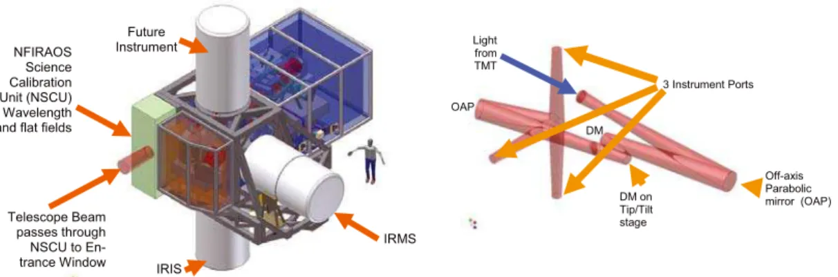
Fig. 1, left, shows the prominent steel exoskeleton that supports the three client instruments, IRIS below, IRMS on the side and a future instrument on top. This instrument support structure also carries NFIRAOS optics cold enclosure, and the NFIRAOS Science Calibration Unit (NSCU). During observations, a mirror inside the NSCU withdraws to allow the telescope beam to pass directly into NFIRAOS. For daytime cali-brations, it sends wavelength and flat-field sources through NFIRAOS to the instruments.
The right side of Fig. 1 shows the NFIRAOS science path. The light from TMT that passes through the NSCU enters NFIRAOS via a double-paned evacuated window and continues to the back of NFIRAOS where it is collimated by an off-axis paraboloidal mirror (OAP). It then continues to a pair of DMs, one of which is on a tip/tilt stage, before being reimaged by a second OAP. Finally an instrument selection fold mirror directs the light up, down, or sideways to instruments.
First conference on Adaptive Optics for Extremely Large Telescopes
Fig. 1. Left: NFIRAOS, client instruments and science calibrator. Right: NFIRAOS Science Path
A functional block diagram is shown in Figure 2. The inset figure shows the same isometric view of the science path surrounded by the other optical paths for wavefront sensing. In the block diagram, the science path travels left to right, depicted by the horizontal line near the bottom of the figure.
Fig. 2. NFIRAOS functional block diagram
For observing, the calibration mirror in the NSCU is retracted and light passes through a protective shutter, and then through the double-paned window into NFIRAOS. There are several deployable calibration de-vices just inside the window. A pin-hole mask is back illuminated by the NSCU for calibrating image dis-tortion and WFS pointing models. A fold mirror and a beamsplitter inject simulated natural and laser guide stars into NFIRAOS. The light continues off the first OAP, and two DMs, and the near-IR passes through a science beamsplitter and is then reimaged by a second OAP. The instrument selection fold mirror has three positions for instruments and a fourth position for a near-IR acquisition camera inside NFIRAOS. The visible light reflected from the beamsplitter travels upwards and is further split between natural and laser light. The laser light is refocused by zoom optics and passed to six wavefront sensors. A single star in the natural visible light beam is selected by a pair of scan mirrors and directed through a field stop and atmos-pheric dispersion corrector (ADC). For laser operation, the visible light is then intensity split between a pair of truth WFSs, working together to provide both high resolution at low frame rates (~0.01 Hz) and
moder-DM on Tip/Tilt stage Light from TMT Off-axis Parabolic mirror (OAP) OAP DM 3 Instrument Ports Telescope Beam passes through NSCU to En-trance Window NFIRAOS Science Calibration Unit (NSCU) Wavelength and flat fields
IRIS
IRMS Future
AOFOR ELT
ate measurement speed (0.1 to 10 Hz) for low order modes. For operation without lasers, a single order 60x60 natural guide star wavefront sensor can control NFIRAOS.
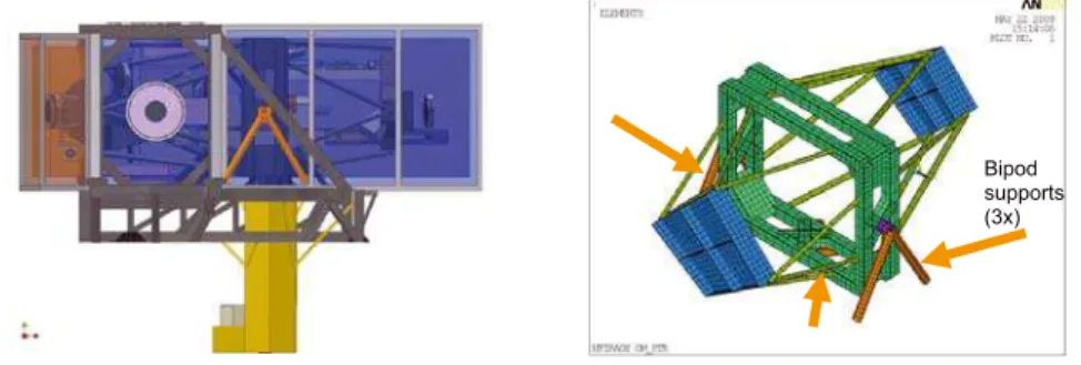
Fig. 3. Left: NFIRAOS optomechanical layout. Right: Space frame concept
The preliminary design of the optics packaging is shown in Fig. 3, which presents a side view in the left panel. The science light from TMT enters from the left and stays in one plane, formed by a collection of commercial optical benches, until it reaches the instrument selection fold mirror. The natural visible light travels upwards to a bench at an upper level, while the laser light is folded down out of the cold enclosure to the laser zoom optics. The right hand panel of the figure shows a recent concept that replaces the com-mercial optical benches with a space-frame, which provides doubled natural frequency (~15 Hz), resistance to earthquakes, and improved access for servicing.
Fig. 4. Left: Bipods support space frame from exoskeleton. Right: Finite element model Space frame concept
Fig. 4 on the left shows one of three bipods supported by the instrument structure. These bipods penetrate into the cooled enclosure and carry the space frame optical support. The right panel of the figure shows these bipods in a finite element model used to assess stiffness and earthquake survivability. TMT and its instruments are required to survive a 1000-year return period earthquake without breaking any glass.
2000 2100 2200 2300 2400 0.01
0.1 1 10
100 15% x (Teles. + Sky) vs NFIRAOS
Wavelength nm ph ot on s / ( a se c^ 2 m ^ 2 n m s )
Fig. 5. Left: Cooling NFIRAOS for observing Efficiency. Right: Lower curve - NFIRAOS background; upper - requirement
Air Handling Unit for cool-down only
Cold plate at -30 C buried near inside of wall, holds temperature
Evacuated double window Copper gasket conducts heat from removable panels to fixed heat exchangers on structure Bipod supports (3x) OAP2 IR Acquisition camera 2 Truth NGS WFSs 1 60x60 NGS WFS OAP1 6 60x60 LGS WFSs 63x63 DM at h=0km On tip/tilt platform 76x76 DM at
Output to science instru-ments and IR T/T/F WFSs Input from telescope
First conference on Adaptive Optics for Extremely Large Telescopes
4 Cooling NFIRAOS
NFIRAOS is allowed to increase the thermal background between OH- lines in the atmosphere by no more than 15% of the background from the sky and telescope. By operating at -30 ° C, NFIRAOS’ background remains below the requirement shown as the upper curve on the right of Fig. 5. The lower curve is the pre-dicted emission from the science path of NFIRAOS including its entrance windows, the science beamsplit-ter and five mirrors. The instrument’s window is not part of NFIRAOS and is not included here. NFIRAOS has a bare porthole for each instrument, closed by a gate valve, and blocked by a manually-installed insu-lated port cover. This allows changing instruments without opening NFIRAOS.
Refrigeration will be done by evaporating R-507 refrigerant. An air-handling unit will be used for initial cool down of NFIRAOS. Once it is at operating temperature, the air-handling unit will be turned off to avoid vibration, and actively cooled walls will intercept heat leakage from the dome. The walls of the op-tics enclosure have two layers of super-insulation with ten times the thermal resistance of polystyrene foam. Sandwiched between the insulation is a buried cold plate conductively cooled by pipes attached to the fixed frame. This design allows removing panels for access, and minimizes temperature gradients throughout the enclosure to avoid convective turbulence.
Although cold operation will help scientific productivity, it does pose some challenge to reliability and per-formance (mechanisms, DMs, tip/tilt stage, coatings Optical alignment). Air leakage into the optics enclo-sure may cause thermal plumes that degrade image quality and allow humidity and frost to form. We are engaged in mitigating these risks. NFIRAOS will be purged with dry air to maintain a slight positive pres-sure. The access panels will be interlocked to prevent removal unless the optics temperature is above the dew point in the dome. Sub-scale DMs and a prototype tip/tilt stage have been tested cold. We are building a sub-scale cold chamber with evacuated window, super-insulation and buried cold plates in walls which will test our enclosure concept and then be used to qualify components (e.g. motorized stages) in the cold.
Rotary
Seal
Bearing
Rotary
Seal
Bearing
Fig. 6. Left: Instrument mounting detail. Right: Instrument interface to NFIRAOS
Each instrument provides rotary bearing to de-rotate the images on its detectors. To retain the cold, each instrument also has a rotary seal that mates with the thermal enclosure of NFIRAOS as shown in Fig. 6. 5 Laser Wavefront Sensors
Fixed Lenses Periscope
AOFOR ELT
Mounted below the cooled enclosure of NFIRAOS is the zoom optics system that refocuses on the sodium layer. A pair of fixed lenses at the plane of the floor of the enclosure is evacuated to form and insulated window. Near focus, periscopes divert the outer pentagonal array of laser images to a wider footprint to provide clearance for the moving optics for each channel. Each WFS uses a polar coordinate CCD[6] and has three lens barrels moving on a common rail to refocus and to reimage the DM onto the lenslet array (with <10% of a lenslet pitch distortion), and compensate non-common path aberrations caused by using a telescope intended for objects at infinity to observe laser beacons as close as 85 km. The right half of the above figure shows an average intensity profile of the sodium layer, which we used to optimize the optics. Each column in the right hand image is vertical profile, showing how the height and structure varies.[10]
6 Auxiliary Optics
NFIRAOS has a near infrared acquisition camera with 1K detectors covering a 2-arcminute field. It will be used to improve observing efficiency by locating the natural guide stars to better precision than the tele-scope pointing accuracy, to quickly acquire these stars on the on-instrument WFSs.
As mentioned earlier, the truth WFS establish offsets for the laser wavefront sensors to reduce centroiding errors caused by the sodium layer structure.
To calibrate the LGS WFS and non-common path errors between these sensors and the science instruments, a laser source simulator reproduces laser guide stars at ranges from 85 to 235 km, but does not simulate elongated spots. It works in conjunction with an array of broadband incandescent point sources that imitate natural stars and feed science detectors and all the other non-laser WFS. Both of these source simulators have adjustable brightness to exercise the NFIRAOS control system.
The NSCU reproduces the telescope exit pupil, which rotates with telescope zenith angle. This will be used to teach the truth WFS what a properly aligned pupil looks like. Then, on the sky, the truth WFS illumina-tion will verify the telescope pupil pointing lookup table. For initial testing of NFIRAOS, at HIA and ide-ally during early integration at TMT, the NSCU will be replaced by a turbulence simulator with a pair of rotating phase screens designed to cause NFIRAOS to reproduce the expected image quality versus radius in the output field of view.
7 Conclusion
NFIRAOS, the first light adaptive optics system for the Thirty Meter Telescope is under design at the NRC Herzberg Institute of Astrophysics in Victoria Canada. Its cooled optics presents challenges which we are actively mitigating, but will offer unprecedented sky coverage and scientific productivity.
References
1. J. Nelson, “Overall science goals and top level AO requirements for TMT,” in Adaptive Optics for Extremely
Large Telescopes, Y. Clenét, J.-M. Conan, T. Fusco & G. Rousset, eds., Paris, 2009.
2. B. Ellerbroek, “Adaptive Optics Systems for the Thirty Mirror Telescope,” Ibid.
3. D. Loop, “Concept study of on-instrument wavefront sensors for the TMT IRIS science instrument,” Ibid. 4. D. Andersen, “Scientific Impact of the Operating Temperature of NFIRAOS on TMT,” Ibid.
5. C. Boyer, “The Laser Guide Star Facility for TMT: requirements overview and current status of the design,” Ibid.
6. S. Adkins et. al, “The design and optimization of detectors for adaptive optics wavefront sensing, in Advances
in Adaptive Optics II, SPIE Proc. 6272, B. Ellerbroek & D. Bonaccini, eds., 2006.
7. G. Hovey, “An FPGA Based Computing Platform for Adaptive Optics Control,” Ibid. 8. R. Conan, “The TMT/NFIRAOS LGS wavefront sensing demonstration bench,” Ibid. 9. O. Lardière, “Characterization and mitigation of Laser-Guide-Star aberration,” Ibid.
10. T. Pfrommer, “High-resolution results from the UBC-lidar experiment for the Thirty Meter Telescope,” Ibid.
First conference on Adaptive Optics for Extremely Large Telescopes