Publisher’s version / Version de l'éditeur:
Vous avez des questions? Nous pouvons vous aider. Pour communiquer directement avec un auteur, consultez la première page de la revue dans laquelle son article a été publié afin de trouver ses coordonnées. Si vous n’arrivez pas à les repérer, communiquez avec nous à PublicationsArchive-ArchivesPublications@nrc-cnrc.gc.ca.
Questions? Contact the NRC Publications Archive team at
PublicationsArchive-ArchivesPublications@nrc-cnrc.gc.ca. If you wish to email the authors directly, please see the first page of the publication for their contact information.
https://publications-cnrc.canada.ca/fra/droits
L’accès à ce site Web et l’utilisation de son contenu sont assujettis aux conditions présentées dans le site LISEZ CES CONDITIONS ATTENTIVEMENT AVANT D’UTILISER CE SITE WEB.
8th International Conference on High Performance Marine Vehicles [Proceedings], 2008
READ THESE TERMS AND CONDITIONS CAREFULLY BEFORE USING THIS WEBSITE.
https://nrc-publications.canada.ca/eng/copyright
NRC Publications Archive Record / Notice des Archives des publications du CNRC :
https://nrc-publications.canada.ca/eng/view/object/?id=77acb4ee-1273-43c4-938e-bb03de3d98a5 https://publications-cnrc.canada.ca/fra/voir/objet/?id=77acb4ee-1273-43c4-938e-bb03de3d98a5
NRC Publications Archive
Archives des publications du CNRC
This publication could be one of several versions: author’s original, accepted manuscript or the publisher’s version. / La version de cette publication peut être l’une des suivantes : la version prépublication de l’auteur, la version acceptée du manuscrit ou la version de l’éditeur.
Access and use of this website and the material on it are subject to the Terms and Conditions set forth at
PROPELLA cavitation assessment for a family of skewed propellers
PROPELLA Cavitation Assessment for a Family of Skewed Propellers
Pengfei Liu
1and J. Michael Doucet
2Institute for Ocean Technology, National Research Council Canada
1 Arctic Avenue, Box 12093, St. John’s, NL Canada A1B 3T5
Email: Pengfei.Liu@nrc.ca
Oceanic Consulting Corporation,
95 Bonaventure Ave., Suite 401, St. John’s, NL Canada, A1B 2X5
E-mail: Michael_Doucet@oceaniccorp.com
ABSTRACT
Cavitation characteristics for a family of skewed propellers were obtained by using an in-house panel method code PROPELLA. The propellers used were the existing NSRDC (US Navy Ship Research and Development Center) skewed propellers. Detailed geometry, open water test data, and results obtained from physical cavitation tunnel tests for these propellers were taken from published literature. Predictions were completed using appropriate wake data (either uniform inflow or measured wake survey data) to determine individual blade spindle torque, in-plane and out-of-plane bending moments and their fluctuations in both open water and behind-ship conditions. For the design speed, cavitation performance was assessed in both the open water and behind-ship conditions to determine thrust and torque breakdown.
1. Introduction
PROPELLA is a comprehensive tool for propeller performance evaluation and design [1]. Its main functionality is briefly listed as follows:
Code Function: Propeller Hydrodynamic Prediction Code
Code Type: Non-linear Unsteady Panel Method
Input Parameters: Propellers with 2 to 10 blades
Nozzles, rudders, stators, propeller pods (optional)
Ice blockages (optional)
Hub & shaft dimensions
Mesh Generator: Allows user-specified paneling (uniform, co-sine, double co-sine)
Input Flow: Uniform or user-defined (axial, tangential & radial values)
Operating Conditions: Advance coefficients from bollard to vanishing thrust
Special Modules: Cavitation module
Output Parameters: Shaft thrust & torque
Shaft transversal forces (vertical, horizontal & resultant)
In-plane & out-of-plane bending moments
Spindle torque
Instantaneous & mean pressure distributions (on blade, nozzle & rudder surfaces)
including Troost B4-55, P4119, P4679, Canadian Coast Guard ice-class open propeller, supply vessel ice-class propeller in nozzle, Marin
propellers B, S, V, IOT-MUN podded propellers, Seiun-Maru propeller, etc.)
Uniform Flow Analysis – Allows comparison of multiple propeller geometries to determine optimum design for efficiency. Parameters such as pitch, rake, skew, number of blades & section shape can be examined easily.
Cavitation Assessment - Heavily loaded propellers can be investigated to determine likely
thrust loss due to cavitation and user set cavitation numbers, in a range of for a wide
range of loading conditions [2].
∞ <
<Cn
0
Non-Uniform Flow – Realistic inflow can be specified to calculate operational characteristics in a ship wake.
Blocked Flow – Ice pieces can be situated in close proximity to the propeller to assess hydrodynamic effects resulting from flow blockages.
Structural Considerations – Estimated propeller shaft normal and resultant forces & moments can be used as input for propeller structural design calculations.
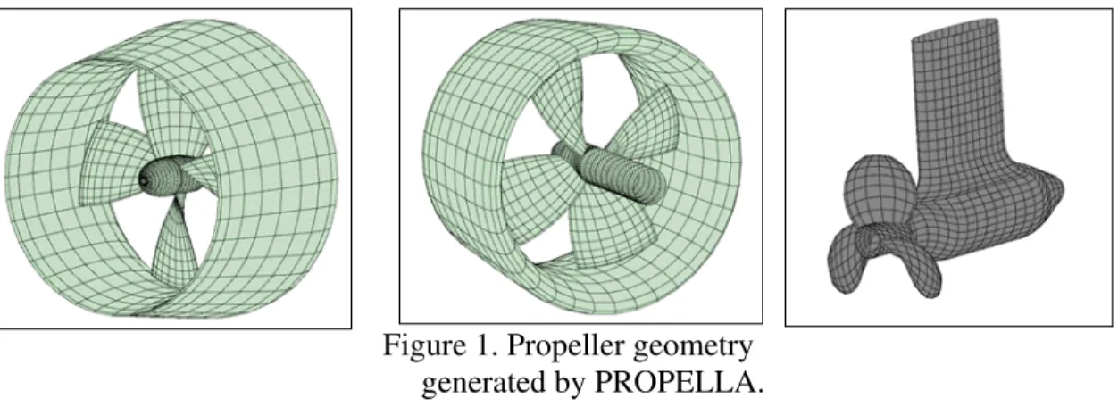
Figure 1 shows some examples of propeller geometry generated by PROPELLA.
Figure 1. Propeller geometry generated by PROPELLA.
For more information on PROPELLA, see a poster attached as Appendix A.
2. Results and Discussion
Validation:
Before the assessment was conducted, a series of validation runs were completed to verify the prediction characteristics of PROPELLA.
In the validation process, a plain DTMB (US David Taylor Ship Model Basin) P4119 propeller was evaluated. Table 1 presents the Kt and Kq values while a. comparison of measured and predicted values, along with an image of the propeller mesh, is shown in figure 2.
David Taylor Ship Model Basin P4119, p/D=1.084 J 0.00 0.20 0.50 0.833 Kt_exp 0.52 0.4220 0.29 0.1460 10Kq_exp 0.76 0.6490 0.48 0.2800 Kt_PROPELLA 0.537 0.436 0.291 0.143 10Kq_PROPELLA 0.762 0.649 0.477 0.271
Table 1. Kt and Kq prediction and measurement
Propella vs Jassup's measurement for Propeller P4119 0.00 0.10 0.20 0.30 0.40 0.50 0.60 0.70 0.80 0.90 -0.15 0.05 0.25 0.45 0.65 0.85 Advance Coefficient K t an d 10kq Kt_exp 10Kq_exp Kt_PROPELLA 10Kq_PEOPELLA
Figure 2. PROPELLA prediction and geometry mesh
An example of cavitation prediction is shown in Figures 3, 4 and 5 for three different advance coefficients. This example shows an Italian high speed propeller, named E03, that was used during a capability enhancement of PROPELLA in 2001 [2], comparing it with previous work by Caponnetto and Brizolara [3].
Experiment (Caponnetto and Brizolara 1995) results and PROPELLA 2008 for a high speed propeller E033
(P/D=1.509) at J=0.8 0.1 0.3 0.5 0.7 0.9 0.50 2.50 4.50 6.50 8.50 Cavitation Number K t an d 10K q Kt Experiment 10Kq Experiment Kt Propella 10Kq Propella
Experimental results (Caponnetto and Brizolara 1995) and PROPELLA for a high speed propeller E033 (P/D=1.509) at J=0.9
0 0.15 0.3 0.45 0.6 0.75 0.5 2.5 4.5 6.5 8.5 Cavitation Number K t and 10K q Kt_Exp 10Kq_Exp Kt_PROPELLA 10Kq_PROPELLA
Figure 4. PROPELLA cavitation prediction for E03 at J=0.9.
Experimental results (Caponnetto and Brizolara 1995) and PROPELLA for a high speed propeller E033 (P/D=1.509) at J=1.0
0 0.1 0.2 0.3 0.4 0.5 0.6 0.7 0.50 1.50 2.50 3.50 Cavitation Number Kt a n d 1 0 Kq KT E 10KQ E Kt_PROPELLA 10Kq_PROPELLA
Figure 5. PROPELLA cavitation prediction for E03 at J=1.0.
Further validation was undertaken using the P4497 propeller by the US Naval Ship Research and Development Centre (NSRDC). The geometry of this propeller has a pitch ratio of 1.1999 with 36 degrees of skew and negative rake, ending up with a 36 degree warp, resulting in an appearance of zero rake.
Open water Characteristic of P4497 0.00 0.20 0.40 0.60 0.80 1.00 1.20 0.00 0.20 0.40 0.60 0.80 1.00 1.20 Advance coefficient K t an d 10K q Kt_Propella 10Kq_Propella Kt_Exp 10Kq_Exp
Figure 6. Current PROPELLA and previous experimental measurement Kt and Kq along with the outline geometry of the P4497 propeller (the 36-degree skew and zero induced rake, i.e. the
warp propeller) [4].
Thrust and Torque Cavitation Breakdown Characteristics:
The cavitation performance assessment was completed with PROPELLA for four propellers marked as A, B, C and D. The geometry details were described by Cumming et al. [4]. Figure 7 shows their geometry shapes as generated by PROPELLA.
Figure 7. Geometry of Propellers A, B, C and D as generated and assessed by PROPELLA. Figures 8, 9, 10 and 11 show the thrust and torque coefficients (Kt and Kq) breakdown due to cavitation, at cavitation numbers Cn_v of 0.6, 1.0, 2.0, 3.0, and 5.0. It is noted that the cavitation
number used in these figures was defined by _ 22
shaft v
n V
gh
C = with a consideration of vapour
pressure. However, a more popular Cn is usually defined by
2 2 2 1 D n P P Cn ref vapor ρ − = , which is also
used in PROPELLA. Therefore, the relationship between Cn_v and Cn is _ 2
J C
C n
v
n = , where J is
the advance coefficient. It also noted that cavitation number Cn_v is a function of advance speed and at J=0.0, Cn_v is infinity. This means that the Cn_v definition cannot assess cavitation performance at very low advance coefficients J.
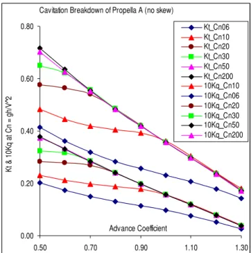
Cavitation Breakdown of Propella A (no skew) 0.00 0.20 0.40 0.60 0.80 0.50 0.70 0.90 1.10 1.30 Advance Coefficient K t & 10K q at C n = gh/V ^2 Kt_Cn06 Kt_Cn10 Kt_Cn20 Kt_Cn30 Kt_Cn50 Kt_Cn200 10Kq_Cn10 10Kq_Cn06 10Kq_Cn20 10Kq_Cn30 10Kq_Cn50 10Kq_Cn200
Figure 8. Thrust and torque breakdown due to cavitation for propeller A.
Cavitation Breakdown of Propella B (36-deg skew)
0.00 0.10 0.20 0.30 0.40 0.50 0.60 0.50 0.60 0.70 0.80 0.90 1.00 1.10 1.20 1.30 Advance Coefficient K t & 10K q at C n = gh/V ^2 Kt_Cn06 Kt_Cn10 Kt_Cn20 Kt_Cn30 Kt_Cn50 Kt_Cn200 10Kq_Cn10 10Kq_Cn06 10Kq_Cn20 10Kq_Cn30 10Kq_Cn50 10Kq_Cn200
Cavitation Breakdown of Propella C (72-deg skew) 0.00 0.10 0.20 0.30 0.40 0.50 0.50 0.70 0.90 1.10 1.30 Advance Coefficient K t & 10K q at C n = gh/V ^2 Kt_Cn06 Kt_Cn10 Kt_Cn20 Kt_Cn30 Kt_Cn50 Kt_Cn200 10Kq_Cn10 10Kq_Cn06 10Kq_Cn20 10Kq_Cn30 10Kq_Cn50 10Kq_Cn200
Figure 10. Thrust and torque breakdown due to cavitation for propeller C.
Cavitation Breakdown of Propella D (108-deg skew)
0.00 0.10 0.20 0.30 0.40 0.50 0.50 0.60 0.70 0.80 0.90 1.00 1.10 1.20 1.30 Advance Coefficient K t & 10K q at C n = gh/V ^2 Kt_Cn06 Kt_Cn10 Kt_Cn20 Kt_Cn30 Kt_Cn50 Kt_Cn200 10Kq_Cn10 10Kq_Cn06 10Kq_Cn20 10Kq_Cn30 10Kq_Cn50 10Kq_Cn200
Figure 11. Thrust and torque breakdown due to cavitation for propeller D.
With the increase of blade skew, it can be seen that the effect of cavitation on thrust and torque breakdown was decreased, although the thrust production and required torque of the propellers were somewhat decreased.
Behind-Ship Cavitation Performance in Terms of Load Fluctuations of
Spindle Torque, In-Plane and Out-of-Plane Bending Moment
Figures 12 and 13 show the shaft Kt and Kq fluctuation due to inflow wake. The inflow wake was taken from an existing wake survey for a fast containership (SEIUN-MARU) [5]. It can be seen that the fluctuation decreases with the increase of skew. Fluctuation on both thrust and torque reduced to nearly zero for Propeller D (with 108-degree skewed blades).
S h a f t K t f l u c t u a t i o n b e h i n d - s h i p a t C n _ v = 3 . 0 , J = 0 . 9 , P r o p e l l e r s A - D - 0 . 6 - 0 . 5 - 0 . 4 - 0 . 3 0 6 0 1 2 0 1 8 0 2 4 0 3 0 0 3 6 0 P o l a r a n g l e N o r t h : 0 , E a s t : 9 0 a n d s o o n K t ( n e g a t i v e v a l u e f o r w a r d t h r u s t ) K t _ A = f ( t ) K t _ B = f ( t ) K t _ C = f ( t ) K t _ D = f ( t )
Figure 12. Shaft Kt fluctuation with inflow wake.
S h a f t K q f l u c t u a t i o n b e h i n d - s h i p a t C n _ v = 3 . 0 , J = 0 . 9 , P r o p e l l e r s A - D - 0 . 1 1 0 - 0 . 0 9 0 - 0 . 0 7 0 0 6 0 1 2 0 1 8 0 2 4 0 3 0 0 3 6 0 P o l a r a n g l e N o r t h : 0 , E a s t : 9 0 a n d s o o n K q ( C C W p o s i t i v e v i e w i n g f r o m s t e r n t o b o w ) K t _ A = f ( t ) K q _ B = f ( t ) K q C = f ( t ) K q D = f ( t )
Figure 13. Shaft Kq fluctuation with inflow wake.
The inflow wake effect on fluctuation of thrust and torque, however, is very obvious for
individual blades, as presented in Figures 14, 15, 16 and 17 which show the thrust fluctuation for 5 blades of each propeller. Torque fluctuations have the same trend and they are omitted here.
B l a d e K q f l u c t u a t i o n d u e t o i n f l o w w a k e C n _ v = 3 . 0 , J = 0 . 9 , P r o p e l l e r A - 0 . 1 8 - 0 . 1 2 - 0 . 0 6 0 0 1 2 0 2 4 0 3 6 0 P o l a r a n g l e N o r t h : 0 , E a s t : 9 0 a n d s o o n K t B l a d e 1 _ A B l a d e 2 _ A B l a d e 3 _ A B l a d e 4 _ A B l a d e 5 _ A
Figure 14. Thrust fluctuation for 5 blades of propeller A.
B l a d e K q f l u c t u a t i o n d u e t o i n f l o w w a k e C n _ v = 3 . 0 , J = 0 . 9 , P r o p e l l e r B - 0 . 1 8 - 0 . 1 2 - 0 . 0 6 0 0 1 2 0 2 4 0 3 6 0 P o l a r a n g l e N o r t h : 0 , E a s t : 9 0 a n d s o o n K t B l a d e 1 _ B B l a d e 2 _ B B l a d e 3 _ B B l a d e 4 _ B B l a d e 5 _ B
Figure 15. Thrust fluctuation for 5 blades of propeller B.
B l a d e K q f l u c t u a t i o n d u e t o i n f l o w w a k e C n _ v = 3 . 0 , J = 0 . 9 , P r o p e l l e r C - 0 . 1 8 - 0 . 1 2 - 0 . 0 6 0 0 1 2 0 2 4 0 3 6 0 P o l a r a n g l e N o r t h : 0 , E a s t : 9 0 a n d s o o n K t B l a d e 1 _ C B l a d e 2 _ C B l a d e 3 _ C B l a d e 4 _ C B l a d e 5 _ C
B l a d e K q f l u c t u a t i o n d u e t o i n f l o w w a k e C n _ v = 3 . 0 , J = 0 . 9 , P r o p e l l e r D - 0 . 1 8 - 0 . 1 2 - 0 . 0 6 0 0 1 2 0 2 4 0 3 6 0 P o l a r a n g l e N o r t h : 0 , E a s t : 9 0 a n d s o o n K t B l a d e 1 _ D B l a d e 2 _ D B l a d e 3 _ D B l a d e 4 _ D B l a d e 5 _ D
Figure 17. Thrust fluctuation for 5 blades of propeller D.
From Figures 14 to 17, it can be seen that, the thrust fluctuation due to inflow wake on the individual blade decreases substantially with increasing skew angle.
Figure 18 shows the spindle torque fluctuation of the first blade (the key blade) for each propeller. K e y b l a d e s p i n d l e t o r q u e f l u c t u a t i o n a l o n g r = 0 . 2 0 6 8 R s e c t i o n ( r o o t s t r i p ) a t 3 2 . 1 7 2 3 0 1 % c h o r d f r o m L . E u n d e r C n _ v = 3 . 0 a n d J = 0 . 9 - 0 . 0 4 0 - 0 . 0 3 0 - 0 . 0 2 0 - 0 . 0 1 0 0 . 0 0 0 0 . 0 1 0 0 6 0 1 2 0 1 8 0 2 4 0 3 0 0 3 6 0 P o l a r a n g l e N o r t h : 0 , E a s t : 9 0 a n d s o o n C o e f f i c i e n t T _ S p i n d l e _ A _ C o T _ S p i n d l e _ B _ C o T _ S p i n d l e _ C _ C o T _ S p i n d l e _ D _ C o
Figure 18. Spindle torque fluctuation of the first blade (the key blade) for 4 propellers. Figures 19 and 20 show in-plane and out-of-plane bending moments for the first blade (the key blade) for all 4 propellers.
K e y b l a d e i n - p l a n e b e n d i n g m o m e n t f l u c t u a t i o n a l o n g r = 0 . 2 0 6 8 R s e c t i o n ( r o o t s t r i p ) a t 3 2 . 1 7 2 3 0 1 % c h o r d f r o m L . E u n d e r C n _ v = 3 . 0 a n d J = 0 . 9 - 0 . 0 1 0 0 . 0 1 0 . 0 2 0 . 0 3 0 6 0 1 2 0 1 8 0 2 4 0 3 0 0 3 6 0 P o l a r a n g l e N o r t h : 0 , E a s t : 9 0 a n d s o o n C o e f f i c i e n t I n _ P l a n e _ A _ C o I n _ P l a n e _ B _ C o I n _ P l a n e _ C _ C o I n _ P l a n e _ D _ C o
Figure 19. In-plane bending moment fluctuation of the first blade (coefficient).
K e y b l a d e o u t - o f - p l a n e b e n d i n g m o m e n t f l u c t u a t i o n a l o n g r = 0 . 2 0 6 8 R s e c t i o n ( r o o t s t r i p ) a t 3 2 . 1 7 2 3 0 1 % c h o r d f r o m L . E u n d e r C n _ v = 3 . 0 a n d J = 0 . 9 - 0 . 0 4 - 0 . 0 2 0 0 6 0 1 2 0 1 8 0 2 4 0 3 0 0 3 6 0 P o l a r a n g l e N o r t h : 0 , E a s t : 9 0 a n d s o o n C o e f f i c i e n t O u t _ o f _ P l a n e _ A _ C o O u t _ o f _ P l a n e _ B _ C o O u t _ o f _ P l a n e _ C _ C o O u t _ o f _ P l a n e _ D _ C o
Figure 20. Out-of-plane bending moment fluctuation of the first blade (coefficient). Figures 21, 22 and 23 show blade Cp distribution and maximum allowable sectional Cp to avoid cavitation, for propeller B’s blades with a 36-degree skew (plots for propellers A, C and D are omitted).
0.00 0.24 0.69 0.99 0.34 0.52 0.68 0.82 0.93 0.98 -3.00 -2.50 -2.00 -1.50 -1.00 -0.50 0.00 0.50 1.00 1.50 -Cp x/c r/R Cp distribution of a blade at 360 degrees (North at 108th time step). Cp
along sections with cavitation shown in green, for propeller B
Figure 21. Cp distribution for the key blade at the 108 time step (0 degree North).
In Figure 21, sections (strips) having cavitation are shown in green. It can be seen that at the leading edge, section 1 has cavitation. Tip sections 10-12 also have cavitation. It is noted that tip cavitation occurred at both the trailing edge and the leading edge of the sections. An improvement on tip section geometry (pitch or camber or a combination of both) should reduce the chance for cavitation. Again, a modified sectional shape (ordinates in terms of camber, thickness and pitch value) might eliminate or reduce the cavitation.
-3.00 -2.50 -2.00 -1.50 -1.00 -0.50 0.00 0.50 1.00 1.50 Cp
Comparison the critical Cp distribution and the blade Cp distribution of a blade at 360 degrees (North at 108th time step). Cp along sections with cavitation shown in green with corresponding blade section's critical Cp, for
propeller B.
Figure 22. Comparison the Cp distribution for the key blade at the 108th time step (0 degree North) and the maximum local allowable cavitation pressure (side view).
Figure 22 shows that the Cp near the root sections (strips 2-7) is much lower than the cavitation limit. Increasing pitch value of these 5 sections to move Cp close to the cavitation limit will increase total thrust without causing cavitation.
0.00 0.24 0.69 0.99 0.34 0. 61 0. 82 0. 96 0. 34 0. 61 0. 82 0. 96 -3.00 -2.50 -2.00 -1.50 -1.00 -0.50 0.00 0.50 1.00 1.50 Cp x/c r/R
Comparison the critical Cp distribution and the blade Cp distribution of a blade at 360 degrees (North at 108th time step). Cp along sections with cavitation shown in green with corresponding blade section's critical Cp, for
propeller B.
Figure 23. Comparison of the Cp distribution for the key blade at the 73rd time step (10 degrees
East of North) and the maximum local allowable cavitation pressure (bird-eye view). An improvement can be made for the tip sections as the Cp at the tip seems to produce a much larger Cp than other tip sections. A suggested improvement would be for the tip sectional profile to have a reduced pitch value, or smaller camber or thickness distribution. A PROPELLA optimization example to improve propeller efficiency with reduced cavitation can be found in a recent work by Liu et al. [6]. It is noted that PROPELLA cannot model the tip geometry accurately due to the abrupt changes in chord length, although a hyperboloid panel formulation was used.
Figure 24 shows a blended color image that simulates cavitation area generated by PROPELLA for the propeller B (inflow wake has been shifted by 90 degrees).
3. Conclusion
PROPELLA was revalidated for behind-ship cavitation assessments using a series of existing skewed propellers. The largest breakdown of thrust and torque under open water cavitation conditions occurred with the Propeller A (zero skew). As skew was increased, the effect of cavitation was shown to decrease. The results also showed that the use of skew reduced the shaft torque and thrust fluctuation substantially, and also reduced the load fluctuations for individual blades. The blade spindle torque was found to be maximum for Propeller D, which had the most skew. In-plane bending moment was found to be maximum for Propeller A (zero skew) and the lowest level of fluctuation was for Propeller C (72-degree skew). Out-of-plane bending moment was highest for Propeller A and was lowest for Propeller D, which also had the lowest level of
fluctuation. Cavitation was predicted for the root section (1st strip) and the blade sections at the
tip region (at the 10, 11 and 12th strips). By comparing the predicted maximum allowable Cp at
each panel with the corresponding propeller produced Cp, it can be seen that PROPELLA can be a useful tool to assess cavitation performance. PROPELLA can also be used to examine possible geometry changes, such as pitch or blade section modifications at the blade tip, to improve propeller performance while minimizing the occurrence of cavitation.
Acknowledgement
The authors wish to thank National Research Council Canada - Institute for Ocean Technology and Oceanic Consulting Corporation for their support.
References
1. Liu, P., PROPELLA Manual, 1999-2008.
2. Liu, P., Neil Bose and Bruce Colbourne, "Incorporation of a critical pressure scheme
into a time-domain panel method for propeller sheet cavitation," International Workshop
on Ship Hydrodynamics (IWSH2001), Wuhan, China, Sept. 22-26, 2001.
3. Caponnetto, M. and Brizzolara, S., “Theory and experimental validation of a surface
panel method for the analysis of cavitating propellers in steady flow”, PropCav 1995,
May16-May18, 14p.
4. Cumming, R.A, Mogan, Wm. B., Boswell, R. J., "Highly Skewed Propellers", Trans. SNAME, Vol. 80, 1972, pp.98-135.
5. Editors: Gindroz, B, Hoshino, T. and Pylkkanen, V., The 22nd ITTC Propulsion
Committee Propeller RANS/Panel Method Workshop, Grenoble, France, 5-6, 1998, 432p.
6. Liu, P., Islam, M.F., Searle, S., McNeil, A. and Prior, A., “Design and optimization of an
ice class propeller under shallow water, semi-tunnel hull and heavy load conditions”,
Proceedings of OMAE 2006, 25th International Conference on Offshore Mechanics and
Arctic Engineering, June 4-9, 2006, Hamburg, Germany.