RESEARCH OUTPUTS / RÉSULTATS DE RECHERCHE
Author(s) - Auteur(s) :
Publication date - Date de publication :
Permanent link - Permalien :
Rights / License - Licence de droit d’auteur :
Bibliothèque Universitaire Moretus Plantin
Institutional Repository - Research Portal
Dépôt Institutionnel - Portail de la Recherche
researchportal.unamur.be
University of Namur
A vision for behavioural model-driven validation of software product lines
Devroey, X.; Cordy, M.; Perrouin, G.; Kang, E.-Y.; Schobbens, P.-Y.; Heymans, P.; Legay, A.;
Baudry, B.
Published in:
Proceedings of the 5th International Symposium On Leveraging Applications of Formal Methods, Verification and Validation (ISoLA)
DOI:
10.1007/978-3-642-34026-0_16 Publication date:
2012
Document Version
Peer reviewed version
Link to publication
Citation for pulished version (HARVARD):
Devroey, X, Cordy, M, Perrouin, G, Kang, E-Y, Schobbens, P-Y, Heymans, P, Legay, A & Baudry, B 2012, A vision for behavioural model-driven validation of software product lines. in Proceedings of the 5th International
Symposium On Leveraging Applications of Formal Methods, Verification and Validation (ISoLA). vol. 7609
LNCS, pp. 208-222, The 5th International Symposium On Leveraging Applications of Formal Methods,
Verification and Validation (ISoLA 2012), Heraclion, Greece, 10/10/12. https://doi.org/10.1007/978-3-642-34026-0_16
General rights
Copyright and moral rights for the publications made accessible in the public portal are retained by the authors and/or other copyright owners and it is a condition of accessing publications that users recognise and abide by the legal requirements associated with these rights. • Users may download and print one copy of any publication from the public portal for the purpose of private study or research. • You may not further distribute the material or use it for any profit-making activity or commercial gain
• You may freely distribute the URL identifying the publication in the public portal ? Take down policy
If you believe that this document breaches copyright please contact us providing details, and we will remove access to the work immediately and investigate your claim.
A Vision for Behavioural Model-Driven Validation of
Software Product Lines
Xavier Devroey1, Maxime Cordy1, Gilles Perrouin1, Eun-Young Kang1, Pierre-Yves
Schobbens1, Patrick Heymans12, Axel Legay3, and Benoit Baudry3
1 PReCISE Research Center, Faculty of Computer Science,
University of Namur, Belgium
2 INRIA Lille-Nord Europe, Universit´e Lille 1 – LIFL – CNRS , France 3 INRIA Rennes Bretagne Atlantique, France
Abstract. The Software Product Lines (SPLs) paradigm promises faster devel-opment cycles and increased quality by systematically reusing software assets. This paradigm considers a family of systems, each of which can be obtained by a selection of features in a variability model. Though essential, providing Quality Assurance (QA) techniques for SPLs has long been perceived as a very difficult challenge due to the combinatorics induced by variability and for which very few techniques were available. Recently, important progress has been made by the model-checking and testing communities to address this QA challenge, in a very disparate way though. We present our vision for a unified framework combining model-checking and testing approaches applied to behavioural models of SPLs. Our vision relies on Featured Transition Systems (FTSs), an extension of tran-sition systems supporting variability. This vision is also based on model-driven technologies to support practical SPL modelling and orchestrate various QA sce-narios. We illustrate one of such scenarios on a vending machine SPL.
Keywords: Software Product Line, Model-Based Testing, Model-Checking
1
Introduction
The manufacturing industry achieved economies of scope based on the idea that a prod-uct of a certain family (e.g., cars) may be built by systematically reusing assets, with some of them common to all family members (e.g., wheels, bodywork, etc.) and others only shared by a subset of the family (e.g., automatic transmission, manual transmis-sion, leather seats, etc.). The Software Product Line (SPL) paradigm [35] applies this idea to software products. In SPL engineering, we usually associate assets with so-called features and we regard a product as a combination of features. Features can be designed and specified using modelling languages such as UML, while the set of le-gal combinations of features (that is, the set of valid products) is captured by a feature model(FM) [24].
As in single-system development, the engineer will have to improve confidence in the different products of an SPL, using appropriate Quality Assurance (QA) techniques. Two popular QA approaches are model-checking and testing. Model checking [6] per-forms systematic analyses on behavioural models in order to assess the satisfaction of
the intended temporal and qualitative requirements and properties. As a complement to model-checking, testing [27] determines whether or not actual executions of the system behave as expected.
In this SPL context, testing or model checking every possible software product rapidly becomes unfeasible, due to a possibly huge number of different combinations of features. This explains why, despite being identified as a research area for years, the development of practical SPL testing techniques is still in an immature stage [14].
This is not a reason to give up, though. On the one hand, we observe significant progress in the SPL verification area and the emergence of efficient model-checking techniques [2, 3, 7, 9, 17, 20, 25, 26]. On the other hand, the testing community has also progressed in this direction by adapting combinatorial interaction testing techniques to the SPL context [32–34]. Furthermore, Model-Based Testing (MBT) [39] is a very efficient approach for addressing test concerns for large and complex systems.
These promising results motivate our will to unify MBT and model checking tech-niques in one framework in order to perform practical, model-based QA of SPLs. It relies upon UML [30] and Featured Transition Systems (FTSs) [8], a formalism for modelling the behaviour of SPLs.
This vision paper sketches this future framework, presenting actual achievements in QA of SPLs and challenges ahead. Section 2 presents a state of the art in variability modelling, model checking and model-based testing. Section 3 gives an overview of the framework and its different QA activities. Section 4 describes how SPL behaviour can be given in UML and how products of interest elicited. Section 5 illustrates QA activ-ities on a running example. Finally, section 6 wraps up with conclusions and outlines future research directions.
2
Background
In this section, we recapitulate theoretical background regarding management of vari-ability and formal verification in SPLs engineering.
2.1 Variability Management
Variability Modelling Pohl et al. define features in [35] as an end-user visible char-acteristic of a system. Features are used by the different stakeholders of a project as an abstraction to support reasoning and are generally represented in a FM. The most common representation for a FM is a Feature Diagram (FD) [24]. For example, Fig. 1 presents the FD of a soda vending machine [8]. A product derived from this diagram will correspond to a set of selected features, for example {v, b, s, cur, eur} corresponds to a machine that sells soda (and only soda) in euro. Such a set is called a configuration of the FM. Feature models have been equipped with formal semantics [36], automated analyses and tools [24] for more than 20 years.
SPL Behavioural Modelling Formalisms allowing the description of SPL behaviour can be classified according to the kind of language they rely upon:
VendingMachine v CancelPurchase c Beverages b FreeDrinks f Currency cur Soda s Tea t Euro eur Dollar usd Or Xor
Fig. 1. Example of Feature Diagram: the soda vending machine [8]
– UML-based approaches. Several approaches consider using UML to model SPL behaviour. For example, Ziadi and J´ez´equel [42] illustrate the usage of UML 2 sequence diagrams and statecharts in the context of product derivation. Czarnecki et al. [12] map features to UML activity diagrams. Our proposal, based on state machines, will be detailed in Section 4.
– Transition system approaches. Fischbein et al. propose in [17] to use Modal Tran-sition Systems (MTSs) to model SPLs with some extensions, which were provided by Fantechi and Gnesi in [15, 16]. Li et al.[26] model each feature as an indepen-dent state machine. The behaviour of a given product is then the state machine that results from the combination of its features.
– Algebraic Approaches. Gruler et al. [20, 19] augment process algebra with an op-erator that allows to model variability in the form of alternative choice between two processes.
UML-based approaches are easy to adopt, based on the lingua franca of modelling. Since UML has no formal semantics, one should be provided [42], especially for QA purposes. MTSs are transition systems with compulsory and optional transitions. Al-though they are able to model optional behaviour, they do not include an explicit notion of features. The same issue arises in the approach proposed by Gruler et al. Finally, Li et al. do not consider cross-cutting features that cannot be modelled as an automaton.
To allow the explicit mapping from feature to SPL behaviour, FTSs [8] were pro-posed. FTSs are Transition Systems (TSs) where each transition is labelled with a fea-ture expression (i.e., a boolean expression over feafea-tures of the SPL), specifying for a given FD in which products the transition may be fired. Thus it is possible to determine which products are the cause of a violation or a failed test.
The semantics of an FTS is a function that associates each valid product with its set of finite and infinite executions, i.e. all the possible paths in the graph available for this specific product. According to this definition, an FTS is actually a behavioural model of a whole SPL. Fig. 2 presents the FTS modelling a vending machine SPL. For instance,
1 2 3 4 5 6 7 8 9 pay/¬f change/¬f free / f take / f close/¬f open/¬f take/¬f cancel / c return / c soda / s serveSoda / s tea / t serveTea / t
Fig. 2. FTS example: the soda vending machine [8]
transition 1 pay/¬ f−→ 2 is labelled with the ¬ f feature expression. This means that only the products that do not have the feature FreeDrinks f are able to execute the transition. While FTSs can be efficiently analysed and verified [9, 7], they are not meant to be designed directly by engineers. In particular, they lack structuring mechanisms. We will illustrate how UML can be combined with FTSs in Section 5.
2.2 Model Checking and Product Lines
Many variability-intensive systems are safety critical. Embedded systems, for instance, are often developed as product lines [13]. The highest levels of QA, including formal verification, are thus needed. Existing verification techniques were mostly developed for single systems. Using those techniques to verify SPLs is tedious, since the number of possible products is exponential in the number of features.
Model checking [6, 4] has proven to be a powerful technique for verifying systems against properties expressed in temporal logics. Classical model checking is currently restricted to single systems, but we started to investigate how to use it efficiently on product lines, taking advantage of the fact that large parts of the behaviour are com-mon to many products. This comcom-monality must already be present in the model. We presented above FTSs. Model-checking also requires a specification formula, that must take variability into account. To this purpose, we defined fCTL and fLTL, that are the well-known logics CTL and LTL (resp.) with additional feature symbols. These sym-bols (called quantifiers) restrict the set of products verified against a given temporal property. As an alternative, one could use the products-restraint operator on FTSs [10]. This operator modifies an FTS so that only the behaviour of specific products is rep-resented in the model. Our model-checking algorithms take the commonality between the products into account and avoid to re-check common behaviour.
Some of the modelling approaches presented above [17, 26, 20, 19] offer model-checking facilities. Yet, because of their feature mapping limitations, they are unable to keep track of the exact behaviour of each product during QA tasks.
2.3 Model-Based Testing and Product Lines
Testing each product of an SPL also faces the same exponential explosion. We therefore need to reason on testing activities at the SPL level, in an abstract manner. MBT [39], like model checking, starts from models of the system under test but provides automated means to derive tests according to test criteria. MBT is thus an excellent candidate to solve this issue. Although behavioural MBT is well established for single-system testing [38], a recent survey [31] shows insufficient support of SPL-based MBT, both in terms of automation and of integration in the development lifecycle. In this paper, we will illustrate a possible integration of testing activities within SPL modelling and QA efforts and focus on the selection of relevant products for testing or/and verification.
3
Overview
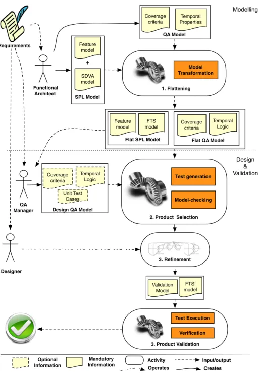
Our vision, sketched in Fig. 3, is based on formal model-driven engineering and aims to provide an end-to-end QA framework for SPL. This framework organizes SPL mod-elling and QA activities within two layers: modmod-elling and design & validation. These activities are orchestrated by three cooperating roles (roles’ interaction is not shown in the figure): functional architect who defines SPL behaviour and specifies criteria for selecting products of interest at the requirements level; QA manager responsible of QA artifacts and the orchestration of QA tasks; and Designer who may refine FTSs with specific behaviour.
Our framework supports the following sequence of activities. First, the SPL is mod-elled according to its requirements. The functional architect specifies the FM repre-senting the variability of the SPL and expresses SPL behaviour in a State Diagram Variability Analysis(SDVA) model. The SDVA formalism is currently under develop-ment and will be defined as a UML profile for state machine diagrams. The purpose of the SDVA model is to facilitate behavioural modelling by using a standard notation that offers richer constructions than pure FTSs. Amongst other things, we will support hierarchical constructs (composite states), useful to abstract details during requirements elicitation and orthogonal states used to model parallel behaviours in sub-states. In ad-dition to this SDVA model, criteria for selecting products of interest are defined.
Second, the obtained SPL model is validated. The hierarchical behavioural models (namely, the SDVA) are flattened into FTSs. The QA manager then proceeds with the selection of a specific set of products, test cases, and temporal properties to verify. As we explain in the sequel, the selection of products can be achieved through the specifi-cation of conditions over the features, test coverage, or model checking. These criteria have been previously defined by the functional architect. The designer may refine the validation model with product-specific properties. For example, one may refine actions defined on FTS transitions with TSs to obtain a full behavioural model of the SPL (de-noted by FTS’ in Fig. 3), allowing in-depth analysis of the selected products. Finally, the product QA manager sets various parameters for the application of validation tools and retrieves validation outcomes (not shown in the figure). The selected products are then verified against the chosen temporal properties and refined test cases define the scenarios to be executed on the SPL’s implementation.
Coverage criteria Temporal Logic Flat QA Model Functional Architect Model Transformation SDVA model + Modelling Design & Validation Designer Feature model Requirements SPL Model Coverage criteria Temporal Properties QA Model FTS model Feature model Flat SPL Model Input/output Validation Model FTS' model Test generation Model-checking 2. Product Selection 1. Flattening Test Execution 3. Product Validation Verification Coverage criteria Temporal Logic Design QA Model Unit Test Cases Activity Mandatory Information Optional Information QA Manager Creates 3. Refinement Operates
4
Modelling SPL behaviour with SDVA
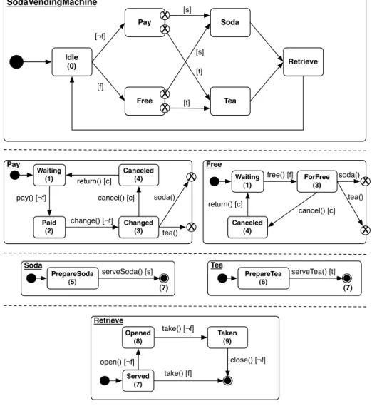
An SDVA is an extension of a state machine diagram with variability operators. As in FTSs, transitions in SDVAs are annotated with constraints over the set of features. A given software product is able to execute a transition if and only if its features satisfy the associated constraint. SDVAs thus combine the modelling constructs of state machines with the conciseness of FTSs (when it comes to representing the behaviour of a set of products). Given that the theory surrounding SDVAs is still undergoing, we present here but a small and intuitive instance of this formalism. Fig. 4 presents an example of SDVA for the FM in Fig. 1. The high-level behaviour of the system as described in the diagram entitled SodaVendingMachine is as follows. The vending machine starts in state Idle. It can transit to either state Pay or Free if the feature f is disabled or enabled, respectively. In both cases, the system can move to state Soda (if the feature sis enabled) or to state Tea (if t is enabled). These two features not being exclusive, there exist products able to execute both transitions. Finally, the system reaches state Retrieve and then goes back to Idle.
This small example already gives account of the advantage of SDVAs over a funda-mental formalism like FTSs. Indeed, one can observe that this SDVA actually models the same behaviour as the FTS shown in Fig. 2. However, the hierarchical construct in SDVAs allows one to define this behaviour at different levels of abstractions. Indeed, we see that the aforementioned high-level behaviour of the system is detailed in five additional diagrams. The effect of features on the system is thus refined as the model reaches deeper abstraction levels.
In addition to the SDVA, the functional architect also has to specify coverage cri-teria. For example, one may be interested in the behaviour of all the vending machines where a drink is eventually served. Through coverage criteria, one can thus drive the selection of relevant execution traces. Alternatively, intended requirements for the sys-tem can be expressed as sys-temporal properties. Once defined, the SPL model and the criteria will be automatically flattened into an FTS and a suitable QA model. Flattening thus provides the SDVA model with a formal semantics in a transformational way. The transformation is an ongoing work and will be based on the flattening algorithm imple-mented using Kermeta [28] and proposed by Holt et al. in their state machine flattener Eclipse plug-in [22]. Although it is possible to flatten some of the most advanced UML state machine diagrams features [40], we currently consider only the hierarchical and orthogonal constructs.
By using FTSs as formal semantics for SDVAs, we want our framework to benefits from the accessibility, attractiveness, and usability of UML-based approaches and from the last advances in behavioural SPL model checking techniques. It is an open method-ological challenge to determine when to stop detailing the SDVA model and proceed to FTS generation and refinement. We believe the SPL size and roles’ skills are important factors impacting this decision. This has to be evaluated in practice.
To define the link between an SDVA and an FM, we propose to use the UML pro-filing mechanism [30, p. 659–688], which allows one to extend metaclasses to adapt them to specific needs and thus to map variable behaviour with the FM. Ziadi et al. [42] use the same profiling mechanism to introduce variability in UML class and sequence diagrams by “tagging” variants and optional elements and incorporating the constraints
SodaVendingMachine Idle (0) Pay Free Soda Tea Retrieve [t] [s] [s] [t] Pay cancel() [c] Waiting (1) Paid (2) pay() [¬f] Changed (3) change() [¬f] Canceled (4) return() [c] Free Canceled (4) ForFree (3) free() [f] Waiting (1) cancel() [c] return() [c] Soda
serveSoda() [s] Tea serveTea() [t]
Retrieve Opened (8) take() [¬f] Taken (9) open() [¬f] close() [¬f] take() [f] (7) (7) [f] [¬f]
X
X
X
X
soda() tea()X
X
X
X
soda() tea() PrepareSoda (5) PrepareTea (6) Served (7)Fig. 4. Vending machine SDVA model.
expressed in the FM using OCL and algebraic specification. The diagrams are then used to synthesize state machines for a given product of the product line. Contrary to this approach where the UML models may be used as standalone, the purpose of SDVA models is (for now) only to facilitate behavioural modelling by using a standard no-tation that offers richer constructions than pure FTSs. Amongst other things, we will support hierarchical constructs (composite states), useful to abstract away from details during requirements elicitation and orthogonal states used to model parallel behaviours in sub-states.
From the SPL model, the last step consists in defining the products that will be covered by the validation activities. Various coverage criteria have been proposed for
state machines such as edge coverage or location coverage [29]. One approach to ex-press this coverage is to directly annotate relevant elements of the model. Although pragmatic, this solution has the disadvantage to increase visual clutter and may become error-prone for large models. Rather, we are in favour of an explicit modelling language to specify coverage criteria. In particular, we rely on the observer automata concept proposed by Blom et al. [5]. Intuitively, an observer monitors the system under test and “accepts” a trace (a possible execution of the state machine) whenever a coverage item defined by the observer is found. We may thus use an observer to select only the traces of a specific subset of products. For example, we may only be interested in products providing drinks for free. Furthermore, we are not interested in cancelling orders for free drinks. The resulting observer is illustrated in Fig. 5. From the initial location, the observe can reach the accepting location freeDrinks if the predicate on the transition evaluates to true, that is if the feature f is selected and c is not.
selected(f ⋀¬c)
freeDrinks
Fig. 5. An observer covering “free drinks” products
In principle, given an SDVA model and an observer, it would be possible to derive all products satisfying the freeDrinks predicate. However, the SDVA model above has only an intuitive semantics and since it is hierarchical, this model raises an issue for the application of the coverage criteria. Indeed, as explained by Weißleder [41], it is not obvious how to traverse outgoing transitions of a composite state. To resolve these issues, we gave our SDVA model a formal semantics by translating it into an FTS. Since FTSs are flat, the application of the coverage criteria can be made more explicit. For example, flattening the SDVA model of Fig. 4 yields the FTS is presented in Fig. 2. The flattening operation usually consists in three steps [1, 18, 23]. First, the SDVA machine is recursively flattened by replacing all states by their sub-machines. We then have one “expanded state machine” with redundancy (e.g., the Waiting state in the Pay and Free sub-machines) and empty transitions (e.g., from Retrieve to Idle). The second step consists in simplifying the expanded state machine by merging redundant states (e.g., Changed and ForFree) and deleting useless ones (e.g., Idle since it has only unconstrained incoming transitions). In the last step, the SDVA operations are transformed into FTS actions. The complete mapping of the SDVA states to the FTS is given under each state of Fig. 4. Note that Idle state is mapped to 0. It means that this state is useless and will not appear in the FTS. To merge equivalent states in FTS, one could apply algorithms like simulation quotient to FTS. Simulation quotient is more complex in FTS than in usual TSs and has been studied in [11]. In the end, we are able to verify the correctness of the flattening transformation and the preservation of properties.
Since the observer’s predicate is expressed in terms of feature expressions and does not directly involve composite states (such as Idle, Retrieve on top of Fig. 4), it does not have to be translated. The definition of compact and reusable observers is an open research question.
An alternative to achieve the selection of products is the explicit specification of the desired and forbidden features. In this case, the validation will rely on the use of a formal operator to prune the flattened FTS from the behaviour of the products that must be ignored, as we will explain in the following section.
5
Validation of Refined SPLs
In this section, we consider a validation scenario exemplifying the SPL validation using a design QA model provided by the QA manager and refinements of the validation model provided by the designer. We illustrate this possible scenario on our vending machine example.
5.1 Design & Validation
The first step in the design and validation part is the product selection, solely based on the flat SPL and QA models or on those models with an additional design QA model provided by the QA manager. The selected products are then refined by the designer according to the desired detail level and validated in the last step.
Product Selection As mentioned in Section 3, product selection can be performed via two ways: by using a test coverage algorithm or a model checker:
1. Considering our observer automata (see Fig. 5), an algorithm computing a TS sat-isfying this observer has been provided [21, 5]. It consists in composing the ob-server and the TS to systematically explore possible transitions (i.e., transitions whose associated feature expression is compatible with the formula f ∧ ¬c) and form “traces”, which are in our case the desired products’ TSs. There are various strategies to generate such traces (e.g., longest [21]). We also need to ensure the uniqueness of traces. Providing feature-oriented strategies as well as an extension of the observer language (to deal with predicates defined over features as shown above) is a research challenge to be tackled.
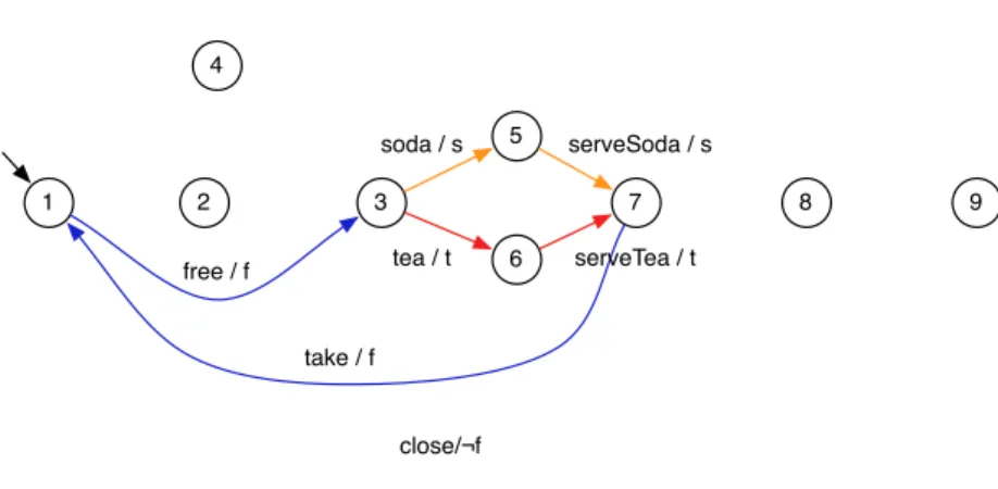
2. Use the products-restraint operator defined in [10]. Given an FTS and a feature valuation function (i.e., a partial function that associates features with Boolean val-ues), this operator removes any transition in the FTS whose feature expression is incompatible with the feature valuation function. Also note that the behaviour of an individual product can be extracted from the individual FTS thanks to a total fea-ture valuation function. Applied on our vending machine example and the function that associates f to true and c to false, the products-restraint operator produces the FTS shown Fig. 6. This FTS models exactly the behaviour of the products with free drinks and no possibility to cancel orders.
1 2 3 4 5 6 7 8 9 free / f take / f close/¬f soda / s serveSoda / s tea / t serveTea / t
Fig. 6. Restrained FTS for free and non-canceling products
Refinement Once the products of interest have been selected, we may refine them to perform targeted verification and generate detailed test scenarios. This refinement con-sists in providing more behaviour to the FTS’ actions and adding new transitions. Let us assume that we are interested to validate serveTea behaviour; we detail it by pro-viding three actions, prepare (setting up tea leaves), boil (boil water at the adequate temperature) and pour (having the water pass through the leaves and and pour the tea in the cup when it is infused). The refined FTS is shown Fig. 7.
1 2 3 4 5 6 7 8 9 free / f take / f soda / s serveSoda / s tea / t prepare / t 6 6 boil / t pour / t
Fig. 7. Refined FTS detailing “serveTea” behaviour
Product Validation The last step is the validation of the actual products defined in the validation model.
The QA manager is also responsible for designing and managing test cases of the SPL. For instance, the QA manager may want to test that serving tea is correctly
handled by the vending machine. To do so, she can provide a new observer as il-lustrated in Fig. 8. We can reuse the algorithm mentioned above [21, 5] to compute traces. However, the role of these traces is different: they form abstract test case sce-narios to be applied on the selected products rather than the new set of products to be considered. Thus, the algorithm would return a list of actions, like the following one: {free, tea, serveTea, take}.
serveTea
serveTea
Fig. 8. An observer covering all traces where the serveTea action appears
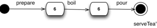
During selection, relevant observers may be elicited by pruning those related to actions not present in the restrained FTS (or the set of product TSs). During refinement, actions can be detailed. This implies that traces have to be refined as well. However, refining traces directly may represent a huge task and may not be easily automated as selection may affect the un-restrained FTS in many ways. Rather, we propose to derive a refined observer as shown in Fig. 9. This observer is much easier to model by the QA manager and may be generated by an automated model transformation, provided that traceability during refinement is maintained. Once obtained, the observer is enabled to derive traces like {free, tea, prepare, boil, pour, take}.
prepare
serveTea'
6 6
boil pour
Fig. 9. Refined observer
Generated traces serve as specification for testers to write concrete test cases to be run on the system implementation.
As in single-system engineering, model checking is an alternative validation tech-nique. In our other work, we have designed efficient algorithms to verify FTSs against properties expressed in temporal logic [9, 7] or as automata [11]. Given a property, such an algorithm returns the exact set of products that do not satisfy the property. To reduce the overhead of verification, our methods tend to take the commonality between the products into account and to avoid redundant checking. We are still extending our work with the aim of providing a wider range of increasingly efficient techniques for formal verification of SPLs.
6
Conclusion & Perspectives
In this paper, we have presented a vision for a model-based behavioural SPL QA frame-work. Our approach relies on formal techniques without sacrificing usability in a unified and flexible enough model-driven framework. We believe that this combination will fos-ter the usage of efficient QA techniques for SPLs thus improving the confidence in the SPL paradigm.
By working on domain artefacts with a variability model, we want our framework to be family-based [37]. The output of the whole chain will be a validation model for (potentially) one product, a subset of products or even the whole product line according to the provided select criteria.
Although some achievements have been made in model checking SPL behavioural models [8], there is still a long way to go before having a complete and coherent SPL quality assessment framework. First, we need to completely define SDVA with appro-priate hierarchical constructs and its semantics as a mapping function from SDVA to FTS. To do this, we will explore existing UML state machines flattening techniques and see how we can adapt them to our needs.
The second challenge is the definition of observers to generate relevant test cases (i.e., interesting traces in the FTS). To define what an “interesting trace” is, we will need to adapt existing test selection criteria and probably create new SPL-dedicated ones.
This leads us to our third challenge: the definition of appropriate test selection al-gorithms dedicated to SPLs. In addition to well-known criteria like all-transitions, we would like to define new ones related to the SPL’s features, which may be relevant from the functional architect’s perspective.
References
1. Ali, S., Hemmati, H., Holt, N., Arisholm, E., Briand, L.: Model Transformations as a Strategy to Automate Model-Based Testing-A Tool and Industrial Case Studies. Simula Research Laboratory, Technical Report pp. 1–28 (01 2010)
2. Asirelli, P., ter Beek, M.H., Fantechi, A., Gnesi, S., Mazzanti, F.: Design and validation of variability in product lines. In: Proceedings of the 2nd International Workshop on Product Line Approaches in Software Engineering. pp. 25–30. PLEASE ’11, ACM, New York, NY, USA (2011)
3. Asirelli, P., ter Beek, M.H., Gnesi, S., Fantechi, A.: Formal description of variability in prod-uct families. In: Proceedings of the 2011 15th International Software Prodprod-uct Line Confer-ence. pp. 130–139. SPLC ’11, IEEE Computer Society, Washington, DC, USA (2011) 4. Baier, C., Katoen, J.P.: Principles of Model Checking. MIT Press (2007)
5. Blom, J., Hessel, A., Jonsson, B., Pettersson, P.: Specifying and generating test cases us-ing observer automata. In: Proceedus-ings of the 4th international conference on Formal Ap-proaches to Software Testing. pp. 125–139. FATES’04, Springer-Verlag, Berlin, Heidelberg (2005)
6. Clarke, E., Grumberg, O., Peled, D.: Model Checking. MIT Press (1999)
7. Classen, A., Heymans, P., Schobbens, P., Legay, A.: Symbolic model checking of software product lines. In: Proceedings 33rd International Conference on Software Engineering (ICSE 2011). ACM Press, New York (2011)
8. Classen, A.: Modelling and Model Checking Variability-Intensive Systems. Ph.D. thesis, PReCISE Research Center, Faculty of Computer Science, University of Namur (FUNDP) (2011)
9. Classen, A., Heymans, P., Schobbens, P., Legay, A., Raskin, J.: Model checking lots of sys-tems: efficient verification of temporal properties in software product lines. In: Proceedings of the 32nd ACM/IEEE International Conference on Software Engineering - Volume 1. pp. 335–344. ICSE ’10, ACM, New York, NY, USA (2010)
10. Cordy, M., Classen, A., Heymans, P., Schobbens, P.Y., Legay, A.: Managing evolution in software product lines: A model-checking perspective. In: Proceedings of VaMoS’12. pp. 183–191. ACM (2012)
11. Cordy, M., Classen, A., Perrouin, G., Heymans, P., Schobbens, P.Y., Legay, A.: Simulation relation for software product lines: Foundations for scalable model-checking. In: Proceed-ings of the 34th International Conference on Software Engineering, ICSE 2012 (to appear). IEEE (2012)
12. Czarnecki, K., Antkiewicz, M.: Mapping features to models: A template approach based on superimposed variants. In: Gl¨uck, R., Lowry, M. (eds.) Generative Programming and Com-ponent Engineering, Lecture Notes in Computer Science, vol. 3676, pp. 422–437. Springer Berlin / Heidelberg (2005)
13. Ebert, C., Jones, C.: Embedded software: Facts, figures, and future. Computer 42(4), 42–52 (2009)
14. Engstr¨om, E., Runeson, P.: Software product line testing-a systematic mapping study. Infor-mation and Software Technology 53(1), 2–13 (January 2010)
15. Fantechi, A., Gnesi, S.: A behavioural model for product families. In: Proceedings of the the 6th joint meeting of the European software engineering conference and the ACM SIG-SOFT symposium on The foundations of software engineering. pp. 521–524. ESEC-FSE ’07, ACM, New York, NY, USA (2007)
16. Fantechi, A., Gnesi, S.: Formal modeling for product families engineering. In: Proceedings of the 2008 12th International Software Product Line Conference. pp. 193–202. IEEE Com-puter Society, Washington, DC, USA (2008)
17. Fischbein, D., Uchitel, S., Braberman, V.: A foundation for behavioural conformance in soft-ware product line architectures. In: Proceedings of the ISSTA 2006 workshop on Role of software architecture for testing and analysis. pp. 39–48. ROSATEA ’06, ACM, New York, NY, USA (2006)
18. Gogolla, M., Parisi Presicce, F.: State diagrams in UML: A formal semantics using graph transformations. In: Proceedings PSMT. pp. 55–72 (1998)
19. Gruler, A., Leucker, M., Scheidemann, K.: Calculating and modeling common parts of soft-ware product lines. In: Proceedings of the 2008 12th International Softsoft-ware Product Line Conference. pp. 203–212. SPLC ’08, IEEE Computer Society, Washington, DC, USA (2008) 20. Gruler, A., Leucker, M., Scheidemann, K.: Modeling and model checking software product lines. In: Barthe, G., Boer, F.S. (eds.) Formal Methods for Open Object-Based Distributed Systems. vol. 5051, pp. 113–131. Springer-Verlag, Berlin, Heidelberg (2008)
21. Hessel, A., Larsen, K., Mikucionis, M., Nielsen, B., Pettersson, P., Skou, A.: Testing real-time systems using UPPAAL. In: Robert Hierons, J.B., Harman, M. (eds.) Formal methods and testing, pp. 77–117. Springer-Verlag (2008)
22. Holt, N.E., Arisholm, E., Briand, L.: Technical report 2009-06: An eclipse plug-in for the flattening of concurrency and hierarchy in uml state machines. Tech. Rep. 2009-06, Simula Research Laboratory AS (2009)
23. Kalnins, A., Barzdins, J., Celms, E.: Model transformation language MOLA. In: Aßmann, U., Aksit, M., Rensink, A. (eds.) Model Driven Architecture, Lecture Notes in Computer Science, vol. 3599, pp. 900–900. Springer-Verlag (2005)
24. Kang, K.C., Cohen, S.G., Hess, J.A., Novak, W.E., Spencer Peterson, A.: Feature-Oriented domain analysis (FODA) feasibility study. Tech. rep., Software Engineering Institute, Carnegie Mellon University (1990)
25. Lauenroth, K., Pohl, K., Toehning, S.: Model checking of domain artifacts in product line en-gineering. In: Proceedings of the 2009 IEEE/ACM International Conference on Automated Software Engineering. pp. 269–280. ASE ’09, IEEE Computer Society, Washington, DC, USA (2009)
26. Li, H.C., Krishnamurthi, S., Fisler, K.: Interfaces for modular feature verification. In: Pro-ceedings of the 17th IEEE international conference on Automated software engineering. pp. 195–204. ASE ’02, IEEE Computer Society, Washington, DC, USA (2002)
27. Mathur, A.: Foundations of software testing. Pearson Education (2008)
28. Muller, P.A., Fleurey, F., J´ez´equel, J.M.: Weaving executability into object-oriented meta-languages. In: Briand, L., Williams, C. (eds.) Model Driven Engineering Languages and Systems, Lecture Notes in Computer Science, vol. 3713, pp. 264–278. Springer Berlin / Heidelberg (2005)
29. Myers, G.: The art of software testing. Wiley (1979)
30. OMG: OMG Unified Modeling Language TM ( OMG UML ), Superstructure. Tech. Rep. August, OMG (2011), http://www.omg.org/spec/UML/
31. Oster, S., W¨obbeke, A., Engels, G., Sch¨urr, A.: Model-based software product lines testing survey. In: Zander, J., Schieferdecker, I., Mosterman, P.J. (eds.) Model-Based Testing for Embedded Systems, pp. 339–382. Computational Analysis, Synthesis, and Design of Dy-namic Systems, CRC Press (September 2011)
32. Oster, S., Zink, M., Lochau, M., Grechanik, M.: Pairwise feature-interaction testing for spls: potentials and limitations. In: Proceedings of the 15th International Software Product Line Conference, Volume 2. pp. 6:1–6:8. SPLC ’11, ACM, New York, NY, USA (2011)
33. Oster, S., Zorcic, I., Markert, F., Lochau, M.: MoSo-PoLiTe: tool support for pairwise and model-based software product line testing. In: Proceedings of the 5th Workshop on Variabil-ity Modeling of Software-Intensive Systems. pp. 79–82. VaMoS ’11, ACM, New York, NY, USA (2011)
34. Perrouin, G., Oster, S., Sen, S., Klein, J., Baudry, B., le Traon, Y.: Pairwise testing for soft-ware product lines: Comparison of two approaches. Softsoft-ware Quality Journal pp. 1–39 (au-gust 2011)
35. Pohl, K., B¨ockle, G., Van Der Linden, F.: Software product line engineering: foundations, principles, and techniques. Springer-Verlag New York Inc (2005)
36. Schobbens, P.Y., Heymans, P., Trigaux, J.C., Bontemps, Y.: Generic semantics of feature diagrams. Computer Networks 51(2), 456–479 (2007)
37. Th¨um, T., Apel, S., K¨astner, C., Kuhlemann, M., Schaefer, I., Saake, G.: Analysis Strate-gies for Software Product Lines. Tech. Rep. FIN-004-2012, School of Computer Science, University of Magdeburg, Germany (April 2012)
38. Tretmans, J.: Model based testing with labelled transition systems. In: Hierons, R.M., Bowen, J.P., Harman, M. (eds.) Formal methods and testing, pp. 1–38. Springer-Verlag, Berlin, Heidelberg (2008)
39. Utting, M., Legeard, B.: Practical model-based testing: a tools approach. Morgan Kaufmann (2007)
40. Wasowski, A.: Flattening statecharts without explosions. SIGPLAN Not. 39(7), 257–266 (June 2004)
41. Weißleder, S.: Test models and coverage criteria for automatic model-based test generation with UML state machines. Ph.D. thesis, Humboldt-Universit¨at zu Berlin (2010)
42. Ziadi, T., J´ez´equel, J.M.: Product Line Engineering with the UML: Deriving Products. In: Pohl, K. (ed.) Software Product Lines, pp. 557–586. Springer Verlag (2006)
![Fig. 1. Example of Feature Diagram: the soda vending machine [8]](https://thumb-eu.123doks.com/thumbv2/123doknet/14566510.726891/4.918.261.671.173.397/fig-example-feature-diagram-soda-vending-machine.webp)
![Fig. 2. FTS example: the soda vending machine [8]](https://thumb-eu.123doks.com/thumbv2/123doknet/14566510.726891/5.918.232.696.172.371/fig-fts-example-soda-vending-machine.webp)