HAL Id: tel-01753002
https://hal.univ-lorraine.fr/tel-01753002
Submitted on 29 Mar 2018HAL is a multi-disciplinary open access archive for the deposit and dissemination of sci-entific research documents, whether they are pub-lished or not. The documents may come from teaching and research institutions in France or abroad, or from public or private research centers.
L’archive ouverte pluridisciplinaire HAL, est destinée au dépôt et à la diffusion de documents scientifiques de niveau recherche, publiés ou non, émanant des établissements d’enseignement et de recherche français ou étrangers, des laboratoires publics ou privés.
Simulation par CFD et mesure en ligne de la
distribution des temps de séjour et la qualité de mélange
dans une extrudeuse bi-vis
Xian-Ming Zhang
To cite this version:
Xian-Ming Zhang. Simulation par CFD et mesure en ligne de la distribution des temps de séjour et la qualité de mélange dans une extrudeuse bi-vis. Autre. Institut National Polytechnique de Lorraine, 2008. Français. �NNT : 2008INPL066N�. �tel-01753002�
AVERTISSEMENT
Ce document est le fruit d'un long travail approuvé par le jury de
soutenance et mis à disposition de l'ensemble de la
communauté universitaire élargie.
Il est soumis à la propriété intellectuelle de l'auteur. Ceci
implique une obligation de citation et de référencement lors de
l’utilisation de ce document.
D'autre part, toute contrefaçon, plagiat, reproduction illicite
encourt une poursuite pénale.
Contact : [email protected]
LIENS
Code de la Propriété Intellectuelle. articles L 122. 4
Code de la Propriété Intellectuelle. articles L 335.2- L 335.10
http://www.cfcopies.com/V2/leg/leg_droi.php
en co-tutelle avec Zhejiang University
!
en génie des procédés d’élaboration des matériaux
"#$"% & " '( )(*+ , ! " #$% &$ ! ' (' )*& + , -,. ( / 0 -! (1 1 ! 2 (3 3$& ,& ( / 4& 2-4 3 ,. / 0
-Abstract
The development of new materials with improved properties seems to rely nowadays more on blending and compounding than on the synthesis of chemically new polymers. Mixing may have a great effect on the morphology and structure of multi-component polymer materials. Therefore, the selection of mixing devices and optimization of processing parameters are two important issues in polymer processing. The twin-screw extruders (TSE) have a modular geometry, which allows adjusting the screw profile to control the axial, dispersive and distributive mixing. TSE are widely used as mixers/reactors for blending, compounding, and reactive processing. Study on mixing in twin-screw extruders has been one of the challenges due to the complex geometry configuration and transient flow pattern. Flow visualization provides qualitative analysis for shearing, stretching, and tearing motions of polymers. Morphological analysis of samples obtained from stopping extruders can not necessarily characterize the dynamic feature in extrusion processing. In-line measurement with numerical simulation is used to study mixing in TSE. Polymer processing is an interdisciplinary field with many unsolved, challenging fundamental research topics and practical applications related to polymer rheology, polymer chemistry and physics, instrument science, mechanical engineering, chemical engineering and computational fluid dynamics (CFD).
This work aimed at developing a new instrument to measure in real time the residence time distribution (RTD) which characterizes the axial mixing and transport abilities of different screw elements based on the analysis of the transient flow pattern and systematic evaluation of mixing theory in TSE. Distributive mixing of polymer melts is characterized by the generation of interfacial area, which is experimentally much more difficult to measure. This 3D numerical simulation based on CFD is adopted. Most relevant results obtained in this work are summarized as follows.
First, we developed a new instrument to measure in real time the RTD in screw extruders based on fluorescent excitation and emission. It possessed two light paths/two optical probes, allowing simultaneous measurement of the RTD at two different locations. The evaluation of the set-up was done in terms of the reproducibility, on the one hand; the linearity between the amplitude of the response signal and the amount of the tracer, on the other hand. Results showed that this device was accurate and reliable for in-line monitoring of the RTD in screw extruders. The
effect of different kneading discs and one special mixing element on local RTD was studied and the screw configurations were designed to match the in-line measurement. The axial mixing quality was characterized by the width of the RTD curve. The result showed that the local RTD of a kneading zone depended very much on the staggering angle of the kneading discs.
Secondly, it was confirmed theoretically and experimentally that specific throughput Q/N, defined as a ratio of throughput (Q) over screw speed (N), was indeed a key process parameter for controlling the dimensionless time distribution, residence revolution distribution (RRD) and residence volume distribution (RVD). For a given value of Q/N, the overall, partial and local RTD were different when Q and N varied. However the corresponding dimensionless RTD as well as the RRD and RVD all fell on single master curves, respectively. The relationship among those three different distributions was established. It was concluded that the mean degree of fill and complete fill length were the same for a given value of Q/N, leading to the superposition of RRD, RVD and dimensionless RTD curves.
Finally, the flow mechanisms and distributive mixing in the kneading disc domain of co-rotating twin screw extruders were studied by the 3-D finite element method. The Mesh Superposition Technique (MST) was introduced to modeling intermeshing twin-screw extruders without calling upon remeshing. A rigorous validation of the model was carried out. Comparison of the 3D model against experimental RTD data is presented. Results confirmed the ability of the model to predict the flow and mixing behavior. Initially, these particles are randomly distributed in an inlet vertical plane and their trajectories between the inlet and outlet are calculated from the velocity profiles. Along each trajectory, the residence time is obtained. The residence time distribution is then obtained based on the residence time of each of those particles. Simulated results are compared with experimental ones obtained by an in-line measurement. The distributive mixing parameters such as the area stretch ratio of material surface η, instantaneous mixing efficiency eη and time-averaged mixing efficiency <eη> are calculated using the interface tracking techniques. These parameters are then used to compare the distributive mixing performance and efficiency of different kneading discs.
Résumé
Aujourd’hui le développement de nouveaux matériaux polymères ayant de bonnes propriétés repose de plus en plus sur des procédés de mélange ou de compoundage de polymères au lieu de recourir à la synthèse de nouvelles molécules. L’action du mélange peut fortement influer sur la morphologie des matériaux polymères multi-constituants. Elle dépend du type de mélangeur et des conditions du procédé. Les extrudeuses bi-vis (TSE) ont une géométrie modulable permettant d’adapter leurs profils de vis aux besoins des mélanges dispersif et distributif. Elles sont souvent utilisées comme mélangeurs/réacteurs pour des procédés de mélange, de compoundage et d’extrusion réactive. Cependant, l’étude sur la qualité du mélange dans les TSE demeure un grand défi en raison de la complexité géométrique et du caractère transitoire de l’écoulement. La visualisation de l’écoulement offre une analyse qualitative de la qualité du mélange. La morphologie des échantillons obtenus par l’arrêt de l’extrudeuse ne permet pas d’analyser le caractère dynamique des procédés d’extrusion. Il serait préférable d’étudier la qualité du mélange dans des TSE à l’aide de mesures en ligne couplées à des simulations numériques. Le “ polymer processing” est un domaine de recherche pluridisciplinaire qui fait appel à la rhéologie, à la chimie, à la physique, à l’instrumentation, au génie des procédés et à la mécanique des fluides numérique et qui présente beaucoup de problèmes fondamentaux à résoudre et beaucoup d’applications pratiques à exploiter.
Cette thèse a pour objet de développer un nouvel instrument en line pour mesurer en temps réel la distribution des temps de séjour (DTS) qui caractérise la performance du mélange axial et la capacité de convoyage de différents types d’éléments de vis basées sur l’analyse de l’écoulement transitoire et l’évaluation systématique de la théorie de mélange dans les TSE. Le mélange distributif des polymères fondus est caractérisé par la génération de l’aire des interfaces, un paramètre difficile à mesurer expérimentalement. Alors on fait appel à des simulations numériques de type CFD. Les principaux résultats obtenus dans ce travail se résument de la manière suivante :
Tout d’abord, un nouvel appareil a été mis au point. Il permet de mesurer en temps réel la DTS dans une extrudeuse bi-vis sur la base du principe d’excitation et d’émission fluorescentes. Il est muni de deux chemins lumineux / deux sondes optiques permettant la mesure simultanée de la DTS à deux endroits différents. La performance de cet appareil a été évaluée en termes de reproductibilité, d’une part; et
de la linéarité entre l’amplitude du signal et la concentration du traceur, d’autre part. Il a été démontré que cet appareil est précis et robuste. L’influence de différents types de disques de mélange et celle d’un élément spécifique sur les DTS locales ont été étudiées. La qualité du mélange axial est caractérisée par la largeur de la courbe de la DTS. Il s’est avéré que la DTS locale d’une zone composée de disques de mélange dépend fortement de leur angle d’hélice.
En deuxième lieu, il a été confirmé théoriquement et expérimentalement que le débit spécifique Q/N, défini comme le rapport entre le débit (Q) et la vitesse de rotation des vis (N), est un paramètre clé du procédé pour contrôler la distribution des temps de séjour adimensionnels, celle des révolutions de séjour (DRS) ainsi que celle des volumes de séjour (DVS). Pour une valeur de Q/N donnée, les DTS globale, partielle et locale varient avec Q et N. Cependant, les DTS adimensionnelles correspondantes ainsi que les DRS et DVS se superposent sur les courbes maîtrises respectives. La relation entre ces trois différentes distributions a été développée. Il a été conclu que lorsque le rapport Q/N est fixe, le taux de remplissage moyen et la longueur remplie sont également fixes. Ce qui conduit à la superposition des courbes de DRS, DVS et DTS adimensionnelles.
Enfin, les mécanismes de l’écoulement ainsi que le mélange distributif dans la zone de mélange d’une extrudeuse bi-vis ont été étudiés par une méthode d’éléments finis 3-D. Une technique de superposition de maillages (MST) est employée pour modéliser l’écoulement dans une extrudeuse bi-vis sans remaillage. Ce modèle a été validé avec des données expérimentales de la DTS. Les résultats confirment la capacité de ce modèle à prédire l’écoulement et la qualité du mélange. D’abord, les particules sont réparties de manière aléatoire sur le plan vertical de l’entrée and leurs trajectoires entre l’entrée et la sortie sont calculés à partir des profils de vitesse. Le temps de séjour est obtenu pour chaque trajectoire. La DTS est alors obtenue à partir du temps de séjour de chacune de ces particules. Les résultats simulés sont comparés avec ceux des expériences obtenues à l’aide de l’appareil de mesure en ligne. Les paramètres du mélange distributif tels que le rapport de l’aire d’étirement de la surface du fluide η, l’efficacité instantanée du mélange eη et la moyenne de l’efficacité du mélange par rapport au temps de mélange <eη> sont calculées en utilisant les techniques de suivi des interfaces. Ces paramètres sont ensuite utilisés pour comparer la performance et l’efficacité du mélange distributif de différents types de disques de mélange.
Acknowledgements
I would like to take this opportunity to recognize the support and contributions of some special individuals without whom I would not have been successful in my research. Most important is the continued instructions, patience, insight and great inspiration for me throughout the entire project made by my advisors, Professors Guo-Hua HU and Lian-Fang FENG. They trained me a lot of important skills necessary for a PhD student. Following your vision of reactive extrusion, I was able to achieve my academic and scientific goals.
I deeply appreciate Dr. Jia-Jun WANG, Ms. Xu-Ping GU, whose expertise, helpful suggestions and friendly guidance in all phase of my study are essential to the accomplishment of this work.
I also like to thank my friends: Guang-Zan LI, Cai-Liang ZHANG, Lu-Gang WANG, Xiao-Bo SONG, Feng-Yong LI, Yu-Hua XUE, Jing CHANG, Wen-Feng ZHANG, Yan-Fei TANG, Jin-Xia LI and Penu CHRISTIAN, who made my experience an enjoyable one. Thank you for your friendship and assisting me with assignments.
I am grateful for the financial support from the China Scholarship Council (CSC) enabled me to complete my study in France in 2007. Without the financial support, it would have been impossible for me to complete my academic pursuits smoothly.
I own a debt of gratitude to my wife, my parents, and my brother, for their patience and understanding. They put my interests above their own needs and desires, yet they still supported me and encouraged me throughout this four-year period.
Table of Contents
Abstract ... iii
Acknowledgements ... v
Table of Contents ... ..vi
List of Figures ... ixx
List of Tables ... xiv
CHAPTER 1 Introduction ... 1
1.1 Classification of Extruders ... 1
1.2 The Residence Time Distribution in Extruders ... 3
1.2.1 Off-line Measurements ... 4 1.2.2 In-line Measurements ... 6 1.2.2.1 Radioactive Methods ... 6 1.2.2.2 Ultrasound Reflection ... 7 1.2.2.3 Electrical Conductivity ... 8 1.2.2.4 Light Reflection... 10 1.2.2.5 Light Transmission ... 11 1.2.2.6 Fluorescence Emission ... 12
1.2.2.7 Magnetic Susceptibility and Other Methods ... 13
1.3 The RTD Simulation Using One Dimension Reactor Models ... 13
1.3.1 Classic Ideal Reactor Models ... 14
1.3.2 New Flow Models ... 16
1.4 The RTD Simulation Using Three Dimension Numerical Simulation ... 17
1.5 Investigations of Distributive Mixing ... 19
1.6 Scope of This Thesis ... 25
1.6.1 Incentive for This Work ... 25
1.6.2 Dissertation Outline ... 26
1.7 References ... 26
CHAPTER 2 Assessing Local Residence Time Distributions in Screw
Extruders through a New In-line Measurement Instrument ... 34
2.1 Introduction ... 35
2.2 Experimental ... 37
2.2.1 Extruder and Screw Configurations ... 37
2.2.2 Materials ... 39
2.2.3 Instrumentation ... 40
2.3 Results and Discussion ... 42
2.3.1 Performance of the New In-Line RTD Measuring Instrument ... 42
2.3.2 Effects of Screw Speed and Feed Rate on RTD ... 46
2.3.3 Assessment of the Local RTD in the Kneading Disc Zone ... 49
2.4 Conclusions ... 53
2.5 Appendix A ... 54
2.6 References ... 57
CHAPTER 3 Local Residence Time, Residence Revolution and
Residence Volume Distributions in Twin-Screw Extruders ... 59
3.1 Introduction ... 60
3.2 Experimental ... 62
3.3 Results and Discussion ... 65
3.3.1 Partial RTD, RRD and RVD ... 65
3.3.2 Local RTD, RRD and RVD ... 75
3.4 Conclusions ... 80
3.5 References ... 82
CHAPTER 4 Numerical Simulation and Experimental Validation of
Mixing Performance of Kneading Discs in a Twin Screw Extruder .. 85
4.1 Introduction ... 86
4.1.1 Simulation and Experimental Validation ... 86
4.1.2 Kinematic Model of Distributive Mixing ... 87
4.2 Numerical Simulation ... 89
4.2.1 Geometry of Kneading Discs ... 89
4.2.2 Numerical Simulation and Material Parameters ... 91
4.2.3 Marker Particle Tracking Analysis ... 93
4.3 Experimental ... 96
4.4 Results ... 97
4.4.2 Effect of Geometrical Parameters on Local Residence Time Distribution
... 100
4.4.3 Distributive Mixing Performance and Efficiency ... 101
4.5 Conclusion ... 108
4.6 References ... 110
Chapter 5 Conclusions and Future Work ... 114
5.1 Conclusions ... 114
List of Figures
Fig. 1.1 Twin-screw extruders of various kinds ... 2
Fig. 1.2 Common elements in co-rotating twin screw extruders. ... 3
Fig. 1.3 Comparison of residence time distribution at different feed rate in a co-rotating twin screw extruder (off-line) ... 6
Fig. 1.4 Extrusion die designed for the ultrasonic method ... 8
Fig. 1.5 Series circuit configuration for measuring melt conductivity response during extrusion ... 9
Fig. 1.6 Reflective optical probe configuration ... 10
Fig. 1.7 Extrusion die designed for the light transmission method ... 11
Fig. 1.8 A schematic diagram of the fluorescence-monitoring device for on-line measurement of the RTD ... 13
Fig. 1.9 Simulation model of screw extruder ... 14
Fig. 1.10 Flow model of single screw extruder ... 15
Fig. 1.11 Schematic diagram of the cluster model ... 17
Fig. 1.12 Schematic plan of dispersive and distributive mixing during extrusion ... 20
Fig. 1.13 The area change of distributive mixing: (a) a stretching-cutting-stacking sequence which yields 2n+1layers after n operations, in this case, n = 2; (b) a stretching-folding transformation yielding 1+2n layers, in this case, n=2. .. 21
Fig. 1.14 Schematic diagram for the pairwise correlation function calculation ... 22
Fig. 1.15 Deformation of infinitesimal elements: line and surface ... 23
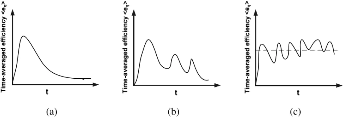
Fig. 1.16 Typical behavior of mixing efficiency; (a) flow with decaying efficiency; (b) flow with partial restoration; and (c) flow with strong reorientation. ... 24
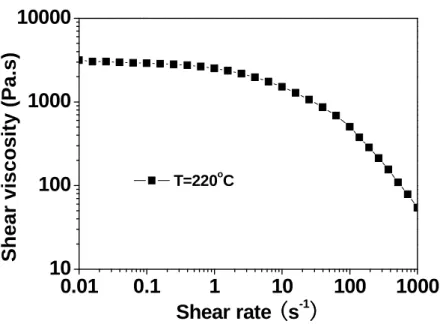
Fig. 2.1. (a) Three locations (three test points) where the RTD probes were placed; (b) details of the screw profile of the kneading zone between probes 1 and 2; (c) details of the three different types of kneading discs used for the kneading zone. A kneading block x/y/z is one which has a length of z mm and y discs. The latter are assembled x degrees one with respect to the other. The set barrel temperature was 220 °C throughout. ... 38 Fig. 2.2 Variation of the viscosity of the polystyrene used in this work as a function of
shear rate at 220 °C. ... 39 Fig. 2.3 Diagram of the in-line RTD measuring system involving three main parts: a
fluorescent light generating source, fluorescent light detection and signal processing. ... 41 Fig. 2.4. A picture and a schematic diagram of optical probe. ... 42 Fig. 2.5 Raw analogue signal (relative voltage) vs. time curves for three repeated
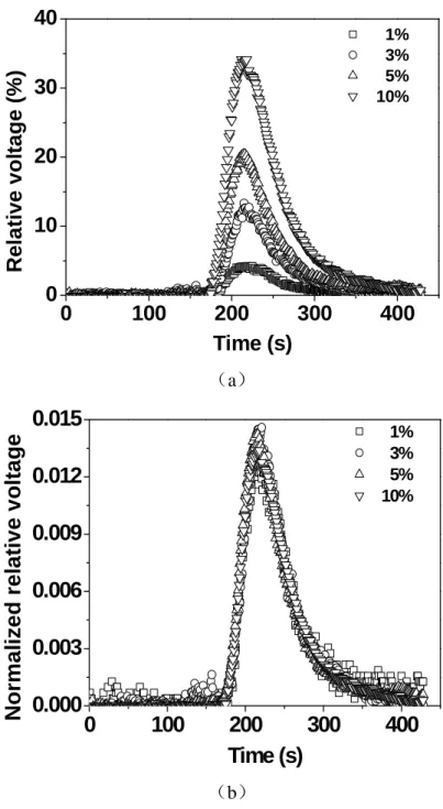
experiments carried out under the following conditions: screw configuration 3; screw speed = 90 rpm, feed rate = 8 kg/h; tracer = masterbatch containing 5% anthracene by mass; amount of the tracer = three pellets. ... 43 Fig. 2.6 (a) Effect of the concentration of the tracer (anthracene) in the masterbatch on
the raw analog signal at probe 3; (b) Normalized relative voltage vs. time curves based on Fig. 2.6a. Screw configuration 1; screw speed = 60 rpm; feed rate = 10.7 kg/h; amount of the tracer masterbatch = 0.1 g (4 pellets); concentration of the tracer in the masterbatch varying from 1 to 10% by mass. The baselines of the raw analogue signal were scaled to zero. ... 44 Fig. 2.7 (a) Effect of the amount of the masterbatch (number of pellets) on the raw
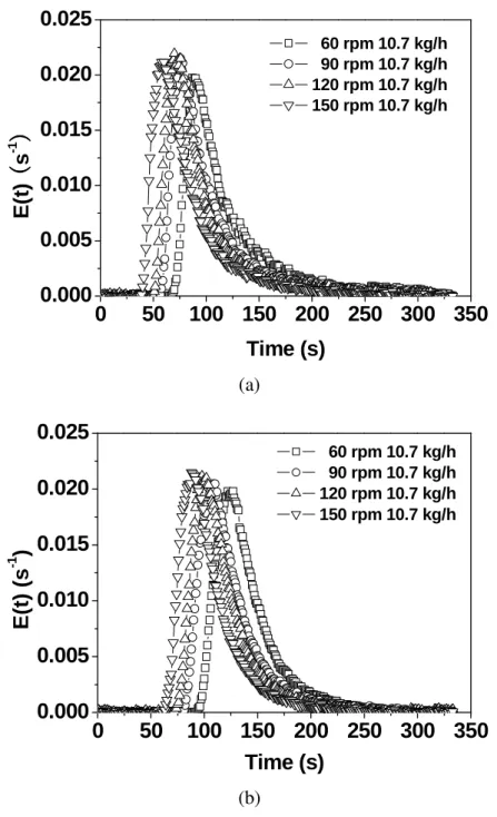
analog signal at probe 3; (b) Normalized relative voltage vs. time curves based on Fig. 2.7a. Screw configuration 1; screw speed = 60 rpm; feed rate = 10.7 kg/h. The baselines of the raw analog signal were scaled to zero. ... 45 Fig. 2.8 Effect of screw speed on the RTD. (a) screw configuration 3 and probe 1; (b)
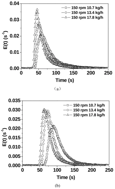
screw configuration 3 and probe 2. ... 47 Fig. 2.9 Effect of feed rate on the RTD. (a) screw configuration 3 and probe 1; (b)
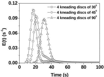
screw configuration 3 and probe 2. ... 48 Fig. 2.10 Effect of the staggering angle of the kneading discs on the partial RTDs. (a)
probe 1 (b) probe 2 (c) probe 3. Screw speed = 120 rpm; feed rate = 15.5 kg/h. ... 51 Fig. 2.11 Effect of the staggering angle on the RTD over the kneading zone between
probes 1 and 2. See Fig. 2.10 for the screw configurations and the operating conditions. ... 52 Fig. 2.12 Effect of the staggering angle on the RTD between probes 2 and 3. See Fig.
2.10 for the operating conditions. ... 52 Fig. 2.13 Effect of the staggering angle on the RTD between probes 1 and 3. The
deconvolution result of E3(t) and E1(t) are agree with convolution results of E12(t) and E23(t) corresponding to Fig. 2.12 and Fig. 2.13 well. See Fig. 10
for the operating conditions. ... 53 Fig. 3.1 (a) Details of the screw profile of the test zone between probes 1 and 2; (b)
locations (test points) of three RTD probes; (c) Detailed geometries of the three different types of kneading blocks and one type of gear blocks used for the test zone. A kneading block x/y/z had a length of z mm and y disc. The latter were assembled x degrees one with respect to the adjacent one. A gear block had two rows of gears along its length of 32 mm. There were 10 gears per row. ... 64 Fig. 3.2 Effect of increasing screw speed and throughput on the RTD for a Q/N of
1.53 ×10⁻³ liter/revolution. (a) Probe 1; (b) probe 2. Screw configuration 1. ... 67 Fig. 3.3 Effect of increasing screw speed and throughput on the RTD for a Q/N of
2.04 × 10⁻³ liter/revolution. (a) Probe 1; (b) probe 2. Screw configuration 1. ... 68 Fig. 3.4 Dimensionless residence time distribution density function E(τ) versus τ
curves corresponding to the E(t) versus t curves in Fig. 3.2. (a) Probe 1; (b) probe 2. Screw configuration 1, Q/N = 1.53 × 10⁻³ liter/revolution. Note that all the E(τ) versus τ curves fall on a single curve. ... 69 Fig. 3.5 Dimensionless residence time distribution density function E(τ) versus τ
curves corresponding to the E(t) versus t curves in Fig. 3.3. (a) Probe 1; (b) probe 2. Screw configuration 1, Q/N = 2.04 × 10⁻³ liter/revolution. Note that all the E(τ) versus τ curves fall on a single curve. ... 70 Fig. 3.6 RRD corresponding to probes 1 and 2, respectively. (a) Probe 1; (b) probe 2;
screw configuration 1; Q/N = 1.53 × 10⁻³ liter/revolution. Note that all the RRD curves overlap. ... 71 Fig. 3.7 RRD corresponding to probes 1 and 2, respectively. (a) Probe 1; (b) probe 2;
screw configuration 1; Q/N = 2.04 × 10⁻³ liter/revolution. Note that all the RRD curves overlap. ... 72 Fig. 3.8 RVD corresponding to probes 1 and 2, respectively. (a) Probe 1; (b) probe 2;
screw configuration 1; Q/N = 1.53 × 10⁻³ liter/revolution. Note that all the RVD curves overlap. ... 73 Fig. 3.9 RVD corresponding to probes 1 and 2, respectively. (a) Probe 1; (b) probe 2;
screw configuration 1; Q/N = 2.04 × 10⁻³ liter/revolution. Note that all the RVD curves overlap. ... 74
Fig. 3.10 Effects of the screw speed (a) and throughput (b) on the local RTD of the
test zone of screw configuration 1. ... 77
Fig. 3.11 Local RTD (a), RRD (b) and RVD (c) curves between probes 1 and 2 for screw configuration 3 at a given Q/N (2.04 × 10⁻³ liter/revolution). They are obtained by deconvolution. Note that all the local RTD, RRD and RVD curves fall on single master curves, respectively. ... 79
Fig. 3.12 Effect of screw configuration on the local RRD and RVD for screw speed: 150 rpm, feed rate: 17.8 kg/h. (a) RTD, (b) RRD and (c) RVD. ... 80
Fig. 4.1 Geometry of the kneading discs and flow channel for simulation. A kneading disc x/y/z is one that has y discs and a total a length of z mm. ... 90
Fig. 4.2 Top view of (a) KD6 with gaps and (b) KD7 without gap ... 91
Fig. 4.3 Viscosity of polystyrene vs. shear rate at 220 °C. ... 93
Fig. 4.4 Schematic diagram for the initial locations of 2000 virtual particles. ... 94
Fig. 4.5 Simulated residence time distributions with different marker particles. (a) KD2, screw speed = 120 rpm, feed rate = 10.7 kg/h; (b) KD3, screw speed = 150 rpm, feed rate = 17.8 kg/h. ... 95
Fig. 4.6 Influence of the initial direction and location of markers, number of marker particles on (a) the arithmetic mean of logη and (b) that of eη. KD2; screw speed = 120 rpm; feed rate = 10.7 kg/h. The normal direction is perpendicular to the surface of the marker particles. Normal direction (0, 1, 0) indicates that the surface of the marker particle is parallel to the xz plane. ... 96
Fig. 4.7 Screw configuration and probe locations for RTD measurements. ... 97
Fig. 4.8 Streamlines of two particles for KD3. Screw speed = 150 rpm; feed rate = 17.8 kg/h. ... 98
Fig. 4.9 Comparison of the local RTD between the numerical and experimental results for different feed rates. ... 99
Fig. 4.10 Comparison of the local RTD between numerical and experimental results for different screw configurations. ... 100
Fig. 4.11 Effect of stagger angle on the local RTD. ... 100
Fig. 4.12 Effects of the disc gap (a) and disc width (b) on the local RTD. ... 101
Fig. 4.13 Axial evolution of logη: (a) arithmetic mean of logη, (b) critical value of logη for given percentiles of marker particles. Screw speed: 150 rpm, feed rate: 17.8 kg/h. ... 103
Fig. 4.14 Effect of the disc gap and disc width on the axial evolution of logη: (a) arithmetic mean of logη, (b) logη for given percentiles of marker particles. Screw speed: 150 rpm, feed rate: 17.8 kg/h. The vertical lines in Fig. 4.14(a) correspond to the locations of the disc gaps of KD6 in Fig. 4.2 ... 104 Fig. 4.15 Axial evolution of time-average efficiency <eη>: (a) arithmetic mean of <eη>,
(b) <eη> for given percentiles of marker particles. Screw speed: 150 rpm, feed rate: 17.8 kg/h. ... 106 Fig. 4.16 Axial evolution of time-average efficiency <eη>: (a) arithmetic mean of <eη>,
(b) <eη> for different percentiles of marker particles. Screw speed: 150 rpm, feed rate: 17.8 kg/h. ... 107 Fig. 4.17 Axial evolution of (a) the arithmetic mean of d(log ) /η dtand (b) that of (D:D)1/2. Screw speed: 150 rpm, feed rate: 17.8 kg/h. ... 108
List of Tables
Table 1.1 Summary of the literature on off-line RTD measurement in extruders ... 5 Table 2.1. Experiments carried out in this work and their operating conditions
(processing temperature: 220°C). ... 40 Table 3.1 Experiments carried out in this work and their operating conditions. The barrel temperature was set at 220 °C throughout the screw length... 64 Table 3.2 Values of tQcorresponding to a given Q/N for four screw configurations in Fig. 3.1 at probes 1 and 2. ... 75 Table 4.1 The description of kneading discs KD1 to KD8 and flow channel in Fig. 4.1.
... 89 Table 4.2 The number of 3D elements for KD1 to KD8 and the flow channel. ... 91 Table 4.3 Operating conditions for the numerical simulations and experiments carried
CHAPTER 1 Introduction
The melt blending of different existing homopolymers is an important route to obtain the specific material properties that homopolymers often cannot accomplish. The mixing of polymer melts is a critical process because the final product properties depend on its uniformity1. However, turbulent mixing is usually unobtainable in polymer processing due to the sufficiently high viscosity of polymer and diffusion coefficients for even very small molecules are exceedingly low. Most polymers in melt processing exhibit “viscoelastic” behavior, meaning that they exhibit not only viscous behavior but also elastic behavior in the liquid state. Viscous energy dissipation during mixing can cause significant temperature variation throughout a vessel, thus contributing to further viscosity nonuniformity, and possibly product degradation2. The above limitations are great challenges for polymer processing. Selection of a mixing device can be complex such as the relationship between the mixing impeller and its position in a mixing vessel is critical to process results.
1.1 Classification of Extruders
Screw extruders are the most important piece of polymer processing equipment. They are divided into two main types: single and twin screw extruders. The key advantages of twin-screw extruders are higher functionality, lower energy consumption and flexibility, which have been widely used for extruding, mixing, and kneading for various polymer materials. Meanwhile, they often used as continuous reactors for preparing multiphase polymer materials such as polymer blends and polymer composites. Twin screw extruders are divided into three types according to the intermeshing structure. These are non-intermeshing, tangential and intermeshing twin screw machines. There are also classified into many types by their rotational direction: co-rotating twin screw extruders and counter rotating twin screw extruders. Fig. 1.1 shows a number of twin screw extruders’ designs which combine the features mentioned above3. Generally speaking twin-screw extruders used in industries are three predominant designs which are intermeshing co-rotating, intermeshing
counter-rotating and non-intermeshing counter-rotating. The advantage of the co-rotating extruders is more flexible and stable extrusion characteristics against fluctuations of pressure and the temperature. The higher output rate can be obtained from the intermeshing counter-rotating extruders, although its extrusion stability is inferior to that of co-rotating extruders4.
Co-Rotation Counter-Rotation Fully intermeshing Partially intermeshing Non- intermeshing
Fig. 1.1 Twin-screw extruders of various kinds
Co-rotation twin-screw extruders are built in a modular fashion to meet the diversity of tasks such as mixing, reaction extrusion and devolatilization. Screw elements are assembled on shafts. They are three main types of elements: full flight conveying elements, kneading discs mixing elements and special mixing elements which are presented in Fig. 1.2.
Full flight conveying elements can have right-handed or left-handed shapes which are characterized by its pitch and length, Right-handed screws are so defined that screw rotation pumps material forward from hopper to the die, and left-handed elements convey material back toward the feed throat. Screw conveying elements can have various numbers of thread starts. Screws with two thread starts are most common (Fig. 1.2a).
The second elements, the kneading discs, are characterized by individual disc length, number of discs and stagger angle between successive discs. The kneading discs can provide the different distributive and dispersive mixing according to the combination of kneading discs. The kneading discs very frequently work under a fully filled channel condition.
Manufacturers of intermeshing co-rotating twin-screw extruders offer various special mixing elements as alternatives to kneading discs to achieve certain mixing function. These included the efforts by Kobe Steel and Farrel Inc., Werner&Pfleiderer, and Berstorff5, 6. The elements can be arranged by the machine user in anyway that is desired to carry out the proposed manufacturing process. Fig. 1.2c shows one classic construction of special element. The purpose of these elements is to provide better mixing due to multiple division, reorientation and recombinations of the flow fluid with less energy consumption. These gear mixing elements are defined by the number of gear around the circumference and the angle of inclination along the axial direction. The gear used to split the flow liquid to generate the interfacial surface; different inclination angles contributed to the different conveying capacity.
(a) Conveying elements (b) Kneading disc (c) Special mixing element Fig. 1.2 Common elements in co-rotating twin screw extruders.
1.2 The Residence Time Distribution in Extruders
The axial mixing in extruders is connected to the residence time distribution (RTD). The RTD has the following applications in extrusion processes:
a) An important use of residence time measurements is to diagnose abnormalities in flow. If the average residence time is lower than expected value (the ratio of fill volume to throughput), it suggests the extruder used has stagnancy. A higher average residence time is more likely to be caused by experimental error7. Therefore, the RTD data are useful for guidance in the selection of appropriate mixing devices and the combination of screw elements.
b) Extrusion of polymers in a screw extruder is composed of a series of thermal, physical and eventually chemical histories/changes occurring in a simultaneous and/or consecutive manner inside the extruder. The time a flow element spends in the extruder can be a measure of the extent of these histories/changes. Thus the RTD provides an aspect of the heating and shearing histories in the screw channel and is helpful for understanding the effects of extrusion variables and screw geometry.
c) For reactive extrusion processes where the reaction time is the same order of mean residence time, for example some types of grafted reaction for polyethylene and polypropylene, the RTD is of interest since the length of time that the material remains in extruder should be closely coupled to the reaction kinetics and hence greatly impact product quality. For example, if a reaction is first order with rate constant k, the knowledge of the RTD allows the reaction yield to be calculated.
d) Although the one dimension (1-D) reactor models and computational fluid dynamic (CFD) methods are increasing popular in the simulation of extrusion processes, experimental validation of simulated results is a big challenge. Velocity measurements are difficult; pressure drop measurements are easy but insensitive to the details of the flow. The global, partial and local RTDs in a twin-screw extruder will be a useful tool for the validation.
1.2.1 Off-line Measurements
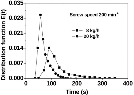
Typically the RTD is measured when the extrusion process has reached a steady state. A tracer is injected to the flow stream (usually at the hopper) as a pulse, the time interval being so short that the input can be considered as a Dirac function. The RTD can be measured off-line, on-line or in-line. Off-line methods are relatively simple in device. A review of off-line measurement in different extruders is presented in Table 1.1. However, measurements are done in a discrete manner. Thus, they are often very time-consuming and generally cannot be performed automatically. Moreover, the resulting data points may not be numerous enough and/or may lack accuracy. Shon et al. 8 used off-line method to measure the RTDs of co-rotating twin-screw extruders. The experimental data are presented in Fig. 1.3 which has small numbers of points and greater scatter in the tail region. This reduces the confidence in the calculated
average residence time and variance. With the development of measurement methods, the off-line will be replaced by in-line or on-line methods step by step.
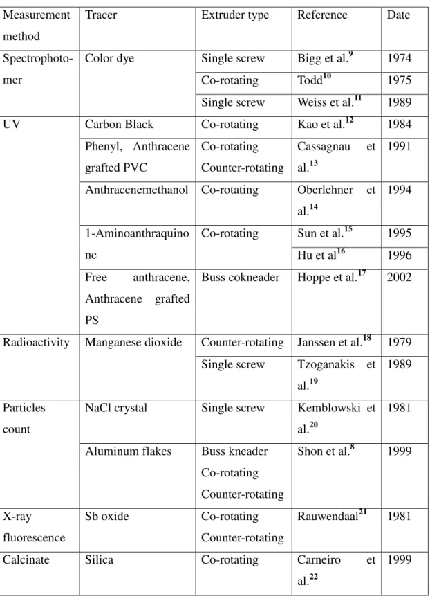
Table 1.1 Summary of the literature on off-line RTD measurement in extruders Measurement
method
Tracer Extruder type Reference Date
Spectrophoto-mer
Color dye Single screw Bigg et al.9 1974 Co-rotating Todd10 1975 Single screw Weiss et al.11 1989 UV Carbon Black Co-rotating Kao et al.12 1984
Phenyl, Anthracene grafted PVC Co-rotating Counter-rotating Cassagnau et al.13 1991
Anthracenemethanol Co-rotating Oberlehner et al.14
1994
1-Aminoanthraquino ne
Co-rotating Sun et al.15 1995 Hu et al16 1996 Free anthracene,
Anthracene grafted PS
Buss cokneader Hoppe et al.17 2002
Radioactivity Manganese dioxide Counter-rotating Janssen et al.18 1979 Single screw Tzoganakis et
al.19
1989
Particles count
NaCl crystal Single screw Kemblowski et al.20
1981
Aluminum flakes Buss kneader Co-rotating Counter-rotating Shon et al.8 1999 X-ray fluorescence Sb oxide Co-rotating Counter-rotating Rauwendaal21 1981
Calcinate Silica Co-rotating Carneiro et al.22
0 100 200 300 400 0.000 0.007 0.014 0.021 0.028 0.035 D is tr ib u ti o n f u n c ti o n E (t ) Time (s) 8 kg/h 20 kg/h
Screw speed 200 min-1
Fig. 1.3 Comparison of residence time distribution at different feed rate in a co-rotating twin screw extruder (off-line)
1.2.2 In-line Measurements
By contrast, in-line measurements continuously analyze the flow material in real time and have no need to collect samples like off-line methods do. Thus, in-line measurements have many advantages over off-line ones23. On-line methods slightly differ from in-line ones in that sample are collected through a bypass and then analyzed. Thus the flow stream is more or less perturbed. However, both sample collection and analysis are done in a continuous manner. Recent studies developed on-line and in-line methods for the RTD measurement that used different tracers and detection devices. Detection principles are based on properties such as radioactivity (MnO2, La2O3, etc.), ultrasound reflectivity (filling, carbon black, etc.), optical reflectivity (TiO2), electrically conductivity (KNO3, NaNO3, KCl, etc.), light transmission (carbon black), and fluorescence emission (anthracene). Advantages and weaknesses of those measurements will be reviewed in the following sections.
1.2.2.1 Radioactive Methods
The radioactive method has a high sensitivity, and even with the low tracer concentrations required which depends on the neutron flux to which the manganese is subjected to during irradiation and the specific isotope used. Wolf and White24 introduced this measurement technology to study the RTDs of a single screw extruder
and counterrotating twin-screw extruders. The tracer used was a masterbatch of 1% manganese dioxide (Mn55 ( , )nγ →Mn56) in PE. The detection of the γ rays emitted by the radioactive tracer was made with a sodium iodide probe. The intensity of the radioactivity of the radioisotope in the sample is a function of radiation time and other parameters by using the following equation:
0.693 0.693 0 0 7 1/ 2 1/ 2 (1 )( ) 3.7 10 i c A N aW t t I e e M t t σ φ − − = − × (1.1)
in which N0 is the Avogadros numbers, σ0 is the cross section of isotope to nuclear
reaction, Φ is neutron flux, a is the natural abundance of active isotope, W is weight
of irradiated sample, t1/2 is the half-life of the radioisotope. Thompson et al.25 used the
radioactive technique to measure the RTDs of a counter-rotating non-intermeshing twin screw extruder. Manganese was chosen for the tracer species. The measuring
system (detector and shielding) is similar to that used by Wolf and White24.
Kiani et al.26, 27 designed a special measuring plate to study the RTD and
morphology simultaneously. The radionuclide Indium-113m with a half time of 100
min are used as labeling agents. Only small amount of these tracers (10-8- 10-6 gm)
are needed as labeling agents due to the high sensitivity. Gamma radiation penetrates the barrel walls of the extruder and enables detection of radiotracer concentration at nearly any point along the length of the machine. The effect of operating parameters on RTD was investigated such as screw speed, screw configuration and feed rate.
As far as the radioactive method is concerned, the sensor must be shielded very carefully to reduce background noise, and the extrudate must be removed immediately. The limitation of this method is that the alpha ray is harmful to our health, and the measurement devices are ponderous.
1.2.2.2 Ultrasound Reflection
Ultrasound method has found numerous uses in widely different fields of application, in particular to characterize composition of polymer blends, the extrusion flow instabilities, the filler concentration, and molecular weight distribution, etc.
Gendron et al.28 proposed ultrasound method for in-line determination of the RTD in
twin-screw extruders. The method is based on the polymer filled by solid particles induced the ultrasound attenuation. Particle concentration is correlated with the intensity of the ultrasound. The result showed that the ultrasound technique is suitable
to monitor RTD in extruders due to its nonintrusive nature and good sensitivity. Chalamet and Taha29 used the same method to research the RTD of reactive extrusion in extruders. The slit die was equipped with two pressure transducers, a thermocouple and ultrasound probe used in the experiment (Fig. 1.4). The effect of the filler nature on RTD, viscosity evolution and condensation reaction were investigated. Comparing the RTDs obtained using the different particle tracers showed the particles have great influence on the results because the tracers change the viscosity of the system.
US
P/T P/T
e Polymer
Fig. 1.4 Extrusion die designed for the ultrasonic method
Lee et al.30 carried out RTD measurement in a co-rotating twin-screw extruder using a non-destructive ultrasonic monitoring system and used CaCO3 as ultrasonic tracer. RTD measurements were carried out with various tracer concentrations, screw speeds, feed rates and screw configurations. The flow in the extruder approached plug flow as the feed rate increased, whereas an increase in the screw speed resulted in the flow approaching mixed flow.
1.2.2.3 Electrical Conductivity
Choudhary and Goutam31 developed a technique of the measuring the RTD in-line based on the electrical conductivity of material in the die and used a series
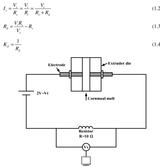
circuit. Change in the current flow was measured by an electrical sensor. Results of this method were reported to be well correlated with those of the well established colored tracer method. Unlu and Faller32, 33 investigated the effects of feed rate screw speed on the RTD and the barrel degree of fill based on electrical conductivity method. The tracer was the Potassium chloride (KCL). The electrical circuit configuration was similar to the one designed by Choudhury and Gautam. Two electrodes were inserted into the extrusion die as probes. The 2V DC-voltage and a 10 Ω resistor composed the circuit and connected with electrodes (Fig. 1.5). The proportional voltage response on the 10R resistance was measured by a digital multimeter and the melt electrical conductivity was obtained from the voltage measurement across the10 Ω resistor using circuit analysis and Ohm's Law expressed as:
s t t s s t s d V V V I R R R R = = = + (1.2) t s d s s V R R R V = − (1.3) 1 d d K R = (1.4)
Fig. 1.5 Series circuit configuration for measuring melt conductivity response during extrusion
at two points in the extruder. The material used for extrusion was a solution of waxy cornstarch in water. The tracer was the mixture of this starch solution, NaCl and water. The extruder used was a transparent model of a corotating twin-screw extruder. The concluded the type and position of mixing elements affected the upstream and downstream RTD and flow pattern.
The electrical conductivity mainly used in food industries with low viscosity and temperature which cannot be used to measure the RTD of polymer melt in extruders.
1.2.2.4 Light Reflection
Wetzel et al.35 used the light reflection method to determine the local RTD in a small section of a co-ratoting twin-screw extruder. A dual probe can be inserted into various positions along the extruder. The working principle of this reflective probe is shown in Fig. 1.6. A bifurcated optical fiber was mounted in a stainless steel shell with a transparent sapphire window. A pulse of a titanium oxide tracer was injected at the feeder and the concentration of the tracer was detected by optical probes at two positions. This measurement gives great flexibility to the research of RTD but relies heavily on the light scattering of the tracer. Polybutene was used as the model fluid which is a Newtonian fluid at the normal shear rate.
Fig. 1.6 Reflective optical probe configuration
Gao et al.36, 37 used the same device to research the mean residence time and RTD in co-ratotaing extruders. According to the results, a predictive model for mean residence time was developed which can be used to explain the experimental results. Elkouss et al.38 investigated the influence of polymer viscoelasticity on the RTD using light reflection method. Based on the detail analysis, they concluded viscoelastic nature of the polymer must be taken into account in analyzing extrusion processes.
However, the probes are sensitive to screw surface reflections and screw rotation which must be excluded from the signal by data processing. Also the correlation between the probe single and tracer concentration is quite difficult and the proper calibration is a great drawbacks.
1.2.2.5 Light Transmission
When an in-line measurement is required, it is necessary to develop a suitable sensor to detect the tracer concentration continuously under extrusion processes. Chen et al.39 selected light transmission method to study the RTD in extruders. A He-Ne laser was used as the light source. A photomultiplier mounted in die was selected to detect the concentration variation of carbon black in PP. From the experimental results, they concluded that light transmission method works well and gives good RTD curves with an error range of less that 6 % of the mean residence time.
Mélo et al.40, 41 presented an in-line transmission light device to measure the RTD curves under continuously extrusion. The measurement system is composed of a slit die with transparent windows (Fig. 1.7). The light source was incandescent W filament microbulb. The polymer used as flow media was PP and the tracer was a masterbatch of organic pigment (blue phthalocyanme) and PP. Measurements were taken from a W&P ZSK 30 twin-screw extruder operating with various screw speeds, feed rate and screw configurations.
1.2.2.6 Fluorescence Emission
Bur et al.42 employed the fluorescence spectroscopy method to measure the flow instability and quality-of-mix of highly filled polymeric systems using a small-molecule fluorescent dye. They hypothesized that the mixing uniform mixing is achieved when the fluorescence intensity is constant with time. Hu et al.23, 43 used the method to measure the RTD in co-rotating extruders. The set-up of the measuring system is shown in Fig. 1.8. The guide/support system was used to guide and support the extrudate and to prevent it from exposure to the daylight. The optical fiber probe can transfer the UV-light generated by mercury lamp and fluorescence emission excited by 9-(methylaminomethyl) anthracene. The tracer was previously incorporated in PS and PMMA backbones, which guarantee the molecular tracers have same rheological and miscible behavior with the extrudate.
Poulesquen et al.44 reported the results of RTD measurements carried out in different extruders with various operating conditions using an in-line fluorescence emission and off-line methods. In order to be able to predict RTD for extrusion processes, a new model without adjustable parameters was presented and validated by the experimental RTD. Cassagnau et al.45 studied the distributive mixing in batch mixers based on the fluorescence monitoring method. Hydroxymethyl anthracene was used as fluorescence tracer and was preliminarily dispersed in the minor component. Structure development during mixing of miscible polymers blends and immiscible polymer blends was investigated by this method. Cassagnau et al.46 used fluorescence emission method to reveal the mixing process of two phases of strongly different viscosity in a co-rotating twin-screw extruder. For miscible binary systems, the RTD of each phase is basically the same. For immiscible binary systems, when the flow rate is high, the shape of the RTD of both phases may be different. Carneiro et al.47 developed an in-line measurement device of RTD based on the light emission. The in-line RTDs in single and co-rotating twin screw extruders were compared with off-line measurements, the agreement is good.
Fig. 1.8 A schematic diagram of the fluorescence-monitoring device for on-line measurement of the RTD
1.2.2.7 Magnetic Susceptibility and Other Methods
The magnetic susceptibility of iron powder for in-line measurement of RTD were used by Puaux et al.48. The described technique demands a relatively simple measurement set-up and is easily adaptable for computer data acquisition. The main purpose of the investigation is to test the one and two-parameter models which can be used to simulate the reactive extrusion. The results showed that the back-flow cell model and ADM model are suitable to fit the experimental data and to explain the physical features of the corotating twin-screw extruder.
Razaviaghjeh et al.49 introduced an in-line method for measuring the RTD of twin screw extruders based on the free radical modification of PE. When a free radical initiator was added into PE melt, the chain branching and crosslinking of PE will increase the viscosity of reaction system, thus lead to an increase of torque of the extruder which can be recorded by a computer. The results measured by this method are in good agreement with that of off-line method. Gilmor et al.50 used spectrometer to quantitatively monitor, in-line, the color of the polymer melt. The variation of color concentration with time can be used to calculate the RTD.
1.3 The RTD Simulation Using One Dimension Reactor
Models
A profound understanding of flow and mixing behavior is necessary to produce the satisfactory products and design the screw configurations. One dimension reactor
model is a method used to predict the RTD, temperature, pressure and the degree of fill. The modeling of flow conditions may be used to predict the extent of reaction along the extruder, to scale in and/or scale-up extruders, to optimize the processing conditions such screw speed, feed rate and operating temperature, and to study the flow instability51, 52. The advantage of the one dimension model is that the calculation cost is relatively small and program is simple.
1.3.1 Classic Ideal Reactor Models
In this model, the RTD during extrusion is first obtained by experiment. Then, conceptual models is used to descript the flow behavior which consist in combinations of ideal reactors such as continuous stirred tank reactors (CSTR) and plug flow reactors (PFR). Each section of the extruder can be considered as an ideal reactor (Fig. 1.9). According to the type of elements constituting the screw profile (left- and right-handed screw elements, kneading discs and special mixing elements), different reactors can be chosen to match the elements. Local RTD and mean residence time of each section can be calculated according to ideal reactors. The global residence time distribution is then done by a product of convolution of these local RTDs.
Numerous flow models have been developed to fit RTD curves in screw extruders. The axial dispersion model (AMD) and CSTR in series are the most common models. The CSTR in series is described by the number of tanks and the volume of each tank. The axial dispersion model is characterized by Peclet number. The CSTR in series can be expanded to many new models such as Gamma model, Wolf-Resnick model, the backflow cell model and the double backflow cell model.
Fig. 1.9 Simulation model of screw extruder
Puaux et al.48 fit the experimental RTD curves with the classic one-, two- and three-parameter models. According to the fitting quality, the three-parameter backflow cell model and two-parameter AMD are the most efficient models. They point out that the two models are consistent with the flow characteristics of co-rotating twin-screw
extruders. Thompson et al. used several classic models to fit the experimental data in order to characterize the material time history in the extruders. The result shows that the AMD provide the closest approach to the RTD.
Chen et al.53, 54 presented a RTD model for intermeshing and non-intermeshing counterrotating twin-screw extruder. They assumed that two-dimensional perfect mixing exists at the boundary of two divided screw elements and treated the screw as a set of individual “C” turns connected in series. The RTDs in the adjacent zones are assumed to statistically independent of each other. The predictions are in good agreement with experimental data.
The RTD is considered as a system parameters like as velocity, pressure and temperature in the extruders which is correlated to process variables and material parameters. Hoppe et al.17 developed a mathematical model consisting of ideal reactors such as CSTR and PFR, and fitted with the experimental data to establish the relationship between model parameters and extrusion conditions. The screw extruder was divided in seven zones and each section was link to an ideal model. The flow models used are shown in Fig. 1.10.
Fig. 1.10 Flow model of single screw extruder
Poulesquen et al.44, 55 coupled the continuum mechanics and chemical engineering techniques to propose a new model for calculating the RTD in the extruders. The new model is also base on the ideal reactors but the selection and association of ideal reactors can reflect the real flow behavior within extruders. They first used the Ludovic software to calculate the mean residence times of the solid conveying, the molten fully filled and partially filled sections. In the second step, the ideal reactors were selected for three sections according to the mean residence time, and local RTD are calculated.
1.3.2 New Flow Models
The RTD is to be strongly dependent on the material parameters and process variables including the screw configurations, feed rate and screw speed. Incomplete understanding of the real flow characteristic in twin-screw extruders and multivariate adjustable parameters may lead to unsatisfactory model result. Therefore, many researchers proposed new models to descript physical features of twin-screw extruders. Kim and White56 investigated the influence of different screw configurations, screw speed and feed rate on the RTD. The result showed that kneading discs and left-handed screw element brought about a remarkable broadening of the RTD. Increasing the feed rate or screw speed resulted in a reduced mean residence time. They used the following model to calculate the mean residence time tm: ( ) f f f f occ m L A L L A V t Q Q ϕ + − = = (1.5)
where Q is the feed rate, Vocc is the occupied volume, Lf is the length of the fully filled region, L is the total length of the screw, φ is the degree of fill, Af is the free cross sectional area of the screw.
De Graaf et al.57 proposed a new model for RTD in a counter rotating twin-screw extruder. The model is based on physical principles without any adjustable parameters and is agreement with the experimental data. The RTD curves are calculated using the following equation: ) ( ) ( ) (t M C t Cout = ℜ µ n in (1.6)
where Cout( )t is the tracer concentration in the die exit, C tin( ) is the input tracer
concentration, ℜ and M are matrices describing the influence of the extruder
parameters (like screw speed, feed rate, screw configuration etc.), is the amount of steps in a revolution, n is time index.
Gao et al.37 presented two new models: residence revolution distribution (RRD)
and residence volume distribution (RVD) which are obtained by the transformation of RTD. The RVD gives a direct measure of the physical distribution of tracer in the extrudate along the axis of the sample. The RRD gives insight into the transport behavior of an extruder. The parameters of the RTD, RRD and RVD model are specified by a least-squares method, and the result showed that the model function is
appropriate to describe the RTD experimental data of different operating conditions. Mehranpour et al.58, 59 established a functionality method for predicting RTD of the modular screw extruders, and named the method as cluster model. The flow model used for calculation is show in Fig. 1.11. When a tracer with concentration C0 passes through the first element, the concentration C(t) at the exit of first element can be determined by the RTD of the element. Also C(t) is the input tracer concentration of the second elements. The output tracer concentration is determined by the second elements. Using the cluster model, they calculated the cumulative RTD of combination of several screw elements.
Fig. 1.11 Schematic diagram of the cluster model
1.4 The RTD Simulation Using Three Dimension
Numerical Simulation
The complexity of the flow in twin-screw extruders, as well as the large number of parameters and interrelated variables that affect the flow, make this process difficult to understand, control, and optimize. The 1-D reactor flow model methods consider an oversimplification of the flow conditions. The main advantage of 1-D reactor model is that it makes the computation and simulation simple, rapid and easy, and can be applied for the process control. However, phenomena described by the flow model are different from the realistic conditions in the extruders. That is to say, the parameters of the model are lack of physical significance. Meanwhile, when a process is calculated, the parameters of the flow model have to be adjusted to satisfy
the operating conditions. The parameters included the number and the type of reactors. Therefore, it cannot be used as predictive tools to describe the real flow and mixing behavior in detail, and are inefficient to solve scale-in and scale-up problems.
The other calculation method is based on computational fluid dynamics (CFD). The flow fields are obtained by solving classical continuum mechanics equations including mass, momentum, energy balances equations. The method can analyze the influence of local geometry, kinematics and boundary conditions on RTD. Because the calculation reflects the real flow and mixing behaviors in extruders, which can be used not only to calculate certain screw configurations such as conveying elements. Kneading discs and special mixing elements, but also to optimize, scale-in and scale-up it and to predict the change of flow fields when changing processing conditions or screw configuration.
Methods used to analyze RTD and distributive and dispersive mixing start by determining the velocity field. Once the velocity field is obtained, a number of different approaches are used to characterize the mixing performance and efficiency. Pinto and Tadmor60 derived the RTD and cumulative RTD functions for screw extruders based on the “parallel plate” model and investigated the influence of operating conditions on RTD. They concluded that the minimum residence time is equal to the 3/4 of mean residence time. Bigg and Middleman9 expanded the study of Pinto and Tadmor60 to non-Newtonian fluid. A model for the 2-D flow field of power-law fluids is developed and used to calculate the RTD. Experiments were carried out to validate the model theory. Joo et al.61 used a quasi-three-dimensional finite element method to calculate velocity field, then proposed a new method to accurately determine the RTD, cumulative RTD taking into account the three-dimensional circulatory flow. The results showed that the previous method based on a simplified two-dimensional velocity field has a tendency to underestimate the RTD due to the neglect of the three-dimensional circulatory flow.
Recently, three-dimensional (3-D) numerical simulations for Newtonian and non-Newtonian fluids have been performed. Bravo et al.62 investigated the flow behavior, particle trajectories and RTD in kneading discs of intermeshing co-rotating twin-screw extruders. It was predicted that particle movement history can be used to evaluate mixing performance of different kneading discs, and the geometry configuration and clearance of kneading discs has important influence on backflow and relative mixing performance. Ishikawa et al.63 investigated the 3-D flow of
non-Newtonian fluid in fully filled kneading discs with different tip clearance of a twin-screw extruder. Large tip clearance narrowed the RTD because of the decrease of backflow. Lawal et al.64 studied the mixing mechanisms in single screw and co-rotating twin-screw extruders based on 3-D numerical simulation. The RTD and numerical tracer analysis were combined to analyze the mixing performance of different screw elements. Meanwhile, Commercial software packages such as Fluent, Polyflow, Fidap and CFX can be used to perform such calculations. Zhu et al.51 used Fluent code to calculate the reactive extrusion process, and investigated the influence of residence time and RTD on conversion rate. Cheng and Manas-Zloczower65 simulated 3-D isothermal flow patterns in conveying element using the FIDAP software based on the finite element method. Distributive mixing was studied by particle tracking and quantified in terms of length, area stretch and strain distributions. Ficarella et al.66, 67 used the code POLYFLOW to simulate the extrusion process. The simulation code is based on a finite element velocity-pressure formulation. They concluded that residence time depend on the screw speed and production temperature.
1.5 Investigations of Distributive Mixing
During polymer processing, dispersive and distributive mixing occur simultaneously. Both types of mixing are required to obtain good properties in the final product. Fig. 1.12 is a schematic representation of a mixing system68. It is possible to regard distributive mixing operation as a transformation from one state to the next. Distributive mixing of polymer melts can be characterized by tracking the spatial distribution of minor phase within the major phase as shown in Fig. 1.12, and by the generation of interfacial area (Fig. 1.13)69, 70. The two methods are much more difficult to measure by experiment approach. Numerical simulation is an effective approach to solve the problems.
Danckwerts71 proposed scale of segregation and the intensity of segregation concepts to characterize the quality of distributive mixing. At time t, consider a set of
J pairs material points separated by a distance r: for the jth pair, let '
j
c and ''
j c
represent the concentrations at both points respectively, let c denote the average concentration of all points. The σc is defined as:
2 2 2 1 ( ) 2 1 J i i c c c J σ = − = −
∑
(1.7) The coefficient of correlation, R(r), measures the degree of correlation between the concentrations at two points separated by distance r which represent the probability of the J pairs materials points will have the same concentrations and is defined as: ' " 1 2 ( )( ) ( , ) J j j j c c c c c R r t Jσ = − − =∑
(1.8) The coefficient of correlation ranges from 1 to -1, denoting, respectively, perfect positive (the J pairs materials points have the same concentration) and perfect negative (the J pairs materials points have the opposite concentration, in other words, one point is pure minor, the other is pure major) correlations. The scale of segregation is the integral of the coefficient of correlation from distance zero, where R(0) = 1, todistance ξ at which there is no correlation R(ξ) = 0.
0
( ) ( , )
S t =
∫
ξR r t dr (1.9)Fig. 1.12 Schematic plan of dispersive and distributive mixing during extrusion a) bad dispersive, bad distributive;;;;b) bad dispersive, good distributive c) good dispersive, bad distributive; d) good dispersive, good distributive
a
b
Fig. 1.13 The area change of distributive mixing: (a) a stretching-cutting-stacking sequence which yields 2n+1layers after n operations, in this case, n = 2; (b) a stretching-folding
transformation yielding 1+2n layers, in this case, n=2.
However, the scale of segregation method has been considered as too complex and was rarely used in practice. Manas-Zloczower’s research group65, 72-75 presented the pairwise correlation function to characterize the degree of distributive mixing. The schematic diagram for the pairwise correlation function calculation is depicted in Fig. 1.14. The black spots represent the minor phase particles. The position of a particle is described by vector r’. The quantification of the distributive mixing can be carried out by tracing the spatial position change of particles. The distance r variation between pairs of particles is an efficient way to quantify the distributive mixing process. The pairwise correlation function is defined as:
2 ( ) (r r) (r ) ( 1) i i i f r N N δ ′ δ ′ = + −
∑
(1.10)where N is the number of particles, which can provide N(N-1)/2 pairs of particles. (r)
δ = 1 if a particle is present and 0 if absent in the shell of radius r± ∆r 2 around the point located at r′ . The f(r) can be interpreted as the probability of finding a