HAL Id: tel-02963225
https://tel.archives-ouvertes.fr/tel-02963225
Submitted on 9 Oct 2020HAL is a multi-disciplinary open access archive for the deposit and dissemination of sci-entific research documents, whether they are pub-lished or not. The documents may come from teaching and research institutions in France or abroad, or from public or private research centers.
L’archive ouverte pluridisciplinaire HAL, est destinée au dépôt et à la diffusion de documents scientifiques de niveau recherche, publiés ou non, émanant des établissements d’enseignement et de recherche français ou étrangers, des laboratoires publics ou privés.
Composite Systems
Pascal Poizat
To cite this version:
Pascal Poizat. Formal Model-Based Approaches for the Development of Composite Systems. Software Engineering [cs.SE]. Université Paris Sud (Paris 11), 2011. �tel-02963225�
Habilitation `a Diriger des Recherches
Pascal POIZAT
Formal Model-Based Approaches for the
Development of Composite Systems
Pr´esent´ee et soutenue publiquement le 24 novembre 2011
Jury
Rapporteurs :
Prof. Mohand-Said Hacid, Universit´e Claude Bernard - Lyon 1, France Prof. Paola Inverardi, Universit`a degli Studi dell’Aquila, Italy
Prof. Fabrice Kordon, Universit´e Pierre et Marie Curie - Paris 6, France
Examinateurs :
Prof. Philippe Dague, Universit´e Paris Sud, France Prof. Marie-Claude Gaudel, Universit´e Paris Sud, France Prof. Ernesto Pimentel, Universidad de M´alaga, Spain
Laboratoire de Recherche en Informatique, UMR 8623 CNRS
Contents i
1 Introduction 1
1.1 Software Architectures . . . 2
1.2 Service Architectures . . . 8
1.3 Composite System Development . . . 12
1.4 General Principles . . . 21
1.5 Preliminary on Formal Models . . . 23
1.6 Summary of the Contributions . . . 30
2 Adaptation and Composition 33 2.1 State of the Art and Contributions . . . 33
2.2 Centralized Adaptation of Software Components . . . 38
2.3 Centralized Adaptation of Web Services . . . 43
2.4 Distributed Adaptation of Semantic Web Services. . . 49
2.5 Automatic Composition of Semantic Web Services . . . 53
3 Verification and Repair 59 3.1 State of the Art and Contributions . . . 59
3.2 Conformance Testing of Service Orchestrations . . . 62
3.3 Conformance Testing of Service Choreographies . . . 65
3.4 Realizability Checking of Choreographies . . . 68
3.5 Repair of Service Orchestrations . . . 70
4 Conclusions and Perspectives 75
5 Publications 79
6 Curriculum Vitæ 85
Bibliography 95
C
h
a
p
t
1
Introduction
My work addresses the application of formal methods to the development of software, that is formal software engineering. Software engineering is concerned about techniques and tools to build software pieces. More than providing a theoretical background for software engineering, formal methods support well-foundedness of the development process, including non ambiguous models and model transformations, and enable the automation of the whole, or parts of, the design and programming activities.
In this context, I have always been interested in the role played by structuring and composition. Blame it on the brick games of my early days, or on my enthusiastic discovery of object-oriented programming in the early 90’s, I have always found interesting to build complex things out of simpler, smaller pieces, especially when one ends up reusing pieces out of some initial blueprint.
This document presents my recent work on structuring in software engineering. It does not try to give a comprehensive presentation of all my research works, nor to give comprehensive technical detailsthat can be found in my papers1.
In this chapter I first introduce the software architecture vision that is a consequence of structuring and composite software systems. Being agnostic to the software target technologies (e.g., programming languages and middleware infrastructures) and to the formal methods been used in the development process, I will present first the software architecture concepts in a generic way, as done in Architectural Description Languages, before showing how these concepts instantiate on service architectures. I will then introduce composite system development processes and related issues. After stressing the recurrent principles in my work, I will finally present an overview of my contributions to these issues. This chapter also includes a short presentation of the formal models I use in my works. It can be skipped in a first reading.
1Most of my papers are available in my Web page. Further, five selected papers will be attached to this
document.
1.1
Software Architectures
Motivation
A major issue one meets when designing a software system is its complexity. Complexity stems first from the size of the system, or from the different aspects that are to be taken into account when developing it. With recent outcomes both in industry (inter-enterprise applications) and for the end-users (social networks, electronic devices and increased connected mobility), software systems get more distributed, shared, and subject to on-demand construction and change than before. Accordingly software complexity increases since several software entities constituting the systems have to be taken into account. Further, these entities do not exist independently from one another. Their interactions are an important part of the problem as they can lead both to benefits (achieving some form of collaboration or cooperation) or to major drawbacks (deadlocks, starvation or incorrect multiple access to resources, etc.).
To solve out such complexity issues, approaches based on the decomposition of a system into sub-systems can be put into practice, whether is it for design, verification, or implementation. Behind the scene of such a decomposition, lies an important concept: structuring. It has been instantiated several times in the past years with approaches based on modules [Parnas, 1972], objects/classes [Dahl and Nygaard, 1966,Meyer, 1997], software components [Szyperski, 1998], services [Papazoglou and Georgakopoulos, 2003], aspects [Filman et al., 2005] or software product lines [Pohl et al., 2005].
Software components make the functionalities provided by some reusable entity explicit, as modules and objects/classes did. However, software components go further by making also the required functionalities explicit. Having both provided and required functionalities explicit supports the definition of software components independently from a specific usage context. This makes, in theory, software components more reusable than modules or objects/classes where requirements are hidden in the code. Services are the basic entities that underpin the development of Oriented Architectures (SOA) and Service-Oriented Computing (SOC). But for differences in description languages and underlying middleware, services can be seen as a kind of software components. Aspect-orientation is a more asymmetric approach, where some first class entity, the base business model or code, is extended with the integration of one or several second class entities called aspects. Software product lines are another modern application of structuring, where products are the result of the integration of core elements and variation-related ones.
All the above-mentioned approaches lead to new software design processes with two distinct tasks2:
• “designing in-the-small”, the design, verification, and implementation or reuse of sub-systems satisfying a subset of the system’s functionalities or corresponding to deployment units.
2The terms “designing in-the-large” and “designing in-the-small” are variations inspired from the terms
• “designing in-the-large”, the structuring of the system as a set of sub-systems linked by dependency or interaction relations, a kind of structural blueprint of the system. In an analogy to building construction where buildings are constructed using an assembly plan for sub-parts (ground, walls, roof), such a blueprint can be referred to as the architectural plan or software architecture of the system, and the person in charge for its definition can be called a software architect.
Elements of an Architecture
In parallel with the development of structured design and programming techniques, the application of formal methods to the architectural vision of software has emerged with Architectural Description Languages (ADLs) [Medvidovic and Taylor, 2000], Coordination Models and Languages [Papadopoulos and Arbab, 1998], and more generally the applica-tion of formal methods to Component Based Software Engineering (see, e.g., the FACS series of conferences) and Service Oriented Computing (see, e.g., the ICSOC series of conferences). In the sequel, I adopt the ADL terminology (Fig.1.1) to present architectural elements due to its technology agnosticism.
ComponentInterface ConnectorInterface Component Interface Connector
Configuration 1 1 0..* 1..* Port 1..* 1..* Role binding
Figure 1.1: Simplified ADL metamodel (UML notation)
Components and Connectors
The basic elements of an architectural model are components and connectors. A component is the basic architectural entity that abstracts some information being available or some piece of code being reusable. To quote [Medvidovic and Taylor, 2000], “A component is a unit of computation or a data store [...]. Components may be as small as a single procedure or as large as an entire application”. The basic motivations that trigger the encapsulation of some information or piece of code as a component are the decomposition of a complex system into smaller sub-systems – the system components – and their interactions, or the desire to enable reuse, following the definition of Szyperski [Szyperski, 1998]: “A software component is a unit of composition with contractually specified interfaces and explicit context
dependencies only. A software component [...] is subject to composition by third-parties”. The former case integrates perfectly in a top-down vision of the software engineering process (decompose to simplify), while the later case corresponds to a bottom-up vision (building value-added systems out of simpler ones).
A connector is the basic architectural entity that abstracts some type of interaction between components. A shared variable in a threaded Java program, a Unix pipe between two commands, a socket between a client and a server, a JDBC connection between a Java program and some database, an HTTP connection between a browser and a Web server, the SOAP connections between an orchestration and basic Web services, tuple spaces, etc. are all examples connectors in every-day life. It is a matter of discussion if there should be any (explicit) connectors at all. Some ADLs have no explicit connectors. It is particularly relevant when there are few kinds of interactions between components, e.g., in Web service composition where SOAP over HTTP is the standard usage. Other ADLs advocate that if connectors are complex they should be defined as components, having again only simple bindings between “component” components and “connector” components, e.g., a complex interaction between two Web services will lead to an orchestration component rather than a connector.
Interfaces
If we refer to the Oxford online dictionary [Oxford University Press, 2010], an interface is “a point where two systems, subjects, organizations, etc. meet and interact”. From a software point of view, the interface of an entity is both the operational mechanism through which this entity interacts with its environment (e.g., a protocol information, an IP address, and a port, such as http://127.0.0.1:8080/), and the contractual specification of the entity functionalities (e.g., “this service provides you with the possibility to buy a trip package provided you give the departure and return dates/places, and for this it will require some plane ticket and hotel booking facility are available”, Fig. 1.2).
As we saw before, an important benefit with reference to earlier approaches is that this specification explicits both the functionalities provided by the entity (here the trip package) and the ones it requires (here online services for plane and hotel booking). The first interpretation of interfaces is mandatory to enable implementability of software architectures. It gives an answer to the question “Where can I access this entity?”. However, ADL go further by using extensively the second interpretation and associated information, and giving an answer to the question “What and how can this entity do something for me? – What and how should I do something for this entity?”. Many ADLs refine interfaces as a set of interaction points that correspond to the first interpretation. An entity has then one interface, made up of one or several interaction points that can be either provided or required. In the component interfaces, these interaction points are called ports, while in the connector interfaces, they are called roles (they correspond to roles that components may play in an interaction).
As an alternative to entities having one interface with several interaction points, one may consider entities that have several interfaces and then do not decompose these into several interaction points, both notions coinciding. Web services for example take this
second interpretation. Let us take a composite Web service. It has different partners it will communicate with. These can correspond to end-users, programs, or other services that will fulfill some functionality for the composite. For each of these partners there is a port, called partner link, which is described using the WSDL language [W3C, 2001].
It is also usual that ports are detailed into sets of operations, the operation being the element being called, and the port being the place where the call is issued. Indeed, many different kinds of information can be associated to an interface (or respectively to ports and roles). This are often classified using four interface description levels [Canal et al., 2006] and respective interface description languages (IDL):
1. Signature level. This is the state-of-the-art of mainstream component and service middleware, e.g., CORBA or SOA such as Web services. Interface descriptions at this level specify the methods or services that an entity offers, as in object IDLs, like CORBA-IDL, or the public interface of a Java class. Sometimes, they also describe its external dependencies, like in component IDLs like CCM-IDL for OMG’s component model, or WSDL for Web Services. Typically, these interfaces specify the name of the service, the type of its arguments and return values, and possibly the exceptions raised, that is, the full signature of the entity behind the interface. This is typically what is described in Figure1.2.
TripService tripClient plane hotel PlaneService planeClient HotelService hotelClient operation book inputs from:string,to:string, departure:date,return:date hotelstars:integer outputs eticket:string, hotel:Hotel operation bookPlane inputs from:string,to:string, departure:date,return:date outputs eticket:string operation setup inputs from:string,to:string, departure:date,return:date outputs sessionid:integer operation book inputs sessionid:integer outputs information:Hotel operation cancel inputs sessionid:integer operation bookPlane inputs from:string,to:string, departure:date,return:date outputs eticket:string operation setup inputs from:string,to:string, departure:date,return:date outputs sessionid:integer operation book inputs sessionid:integer outputs information:Hotel
Figure 1.2: Signature interfaces (Acme ADL notation)
2. Behavioral level. Interfaces at this level specify the protocol describing the in-teractive behavior that a component follows, and possibly the behavior that it expects from its environment. Behavioral descriptions are required for entities
setup
book
cancel setup ; (book ; + cancel ; )
√
√
Figure 1.3: Behavioral interface (process algebraic and LTS notations)
with state, providing non-uniform services which are not available at any time, but that depend for example on the internal state of the entity or on the past history of interactions with their partner(s). This level is essential because the reuse and composition of components can lead to deadlocks or erroneous situa-tions if one is not aware of their execution flows and does not take them into account while building the systems [Vallecillo et al., 2000]. Numerous proposals have been made for the extension of component interfaces with behavioral descriptions, e.g., [Pl´aˇsil and Visnovsky, 2002, Inverardi and Tivoli, 2003, Bracciali et al., 2005,
Poizat and Royer, 2006,Barros et al., 2009]. It is also the case for (Web) services,
e.g., [Ben Mokhtar et al., 2007,Grigori et al., 2008,Bertoli et al., 2010]. Despite po-tential benefits (automated verification, adaptation and composition) many compo-nents do not present a behavioral interface. However, one may retrieve behavioral interfaces using process/protocol mining [Musaraj et al., 2010,van der Aalst, 2011], learning [Steffen et al., 2011], or testing [Bertolino et al., 2009]. ADLs with behav-ioral interfaces rely, for description and analysis, on formal behavbehav-ioral model such as (labeled) transition systems (LTSs), Petri nets, or process algebras (see Sect.1.5). Let us take again the trip service example. To be used, HotelService requires that its user, TripService, calls its three operations in a specific ordering. Such usage protocol can sometimes be inferred from the signature. Here, both the book and cancel operations require as input a session identifier that is provided by operation setup. However, in general behavioral signatures must be given. In our example, setup must be done first, and then either book or cancel may be called (Fig.1.3, where ;, +, and√denote respectively sequence, choice, and termination). This cannot be inferred from the signature.
3. Semantic level. This level describes what the entity actually does, not only the methods it offers, or the messages it exchanges. Such a kind of specification is particularly interesting for component mining, e.g., automatic service discovery and selection [Benatallah et al., 2005b,Hacid et al., 2009]. In the field of Web services, this level of description is related to the Semantic Web, e.g., using ontologies or de-scription logics, and languages such as OWL/OWL-S or WSMO [To¨orm¨a et al., 2008]. An alternative approach consists in using formal functional descriptions for specifying functionality, e.g., preconditions and postconditions for the signature level operations. 4. Non-functional level. Numerous non-functional properties like security, reliability,
accuracy, cost, etc. are important to be taken into account when composing entities altogether. These properties are tackled by the non-functional interface description level. It is usually highly customizable, and the possible descriptions include mean values, standard deviations and a set of quantiles characterizing the distribution of any self-defined quality metric. This description level is of particular interest both for architectural analysis [Bernardo et al., 2002,Balsamo et al., 2004] and for component mining [Zeng et al., 2004,El Haddad et al., 2010].
If most works on software architectures associate with interfaces only a subpart of these four levels, the genericity and extensibility principles of interfaces promote that one can put in an interface description whatever is required to ease specification, analysis, and/or implementation. In my work, I have focused on the first three description levels.
Configurations
An (architectural) configuration is the description of an assembly of components (i.e., a set of identified instances of component types) and connectors (i.e., a set of identified instances of connector types). The relations between components (exchanging provided/required functionalities) is achieved through connectors and the binding of component ports to the different roles of the connectors.
Configurations represent an architectural viewpoint over a system. Different abstractions (e.g., whether we are at design time, or at deployment time where deployment constraints are highly relevant) can lead to different configurations. Configurations enable the designer to check the system’s architecture. Further, once a deployment scheme has been chosen (e.g., if, for each component, an address is given) then automatic deployment of the system
is possible.
An important benefit of configurations, when it comes to take the systems’ complexity into account, is the possibility to build composite components, i.e., to treat a configuration as a component and (re-)use it in further configurations. For this, it must be possible to relate the ports of the composite components to the ports of its sub-components. Composite components enable a divide-and-conquer strategy where, for example, a first decomposition level of a system can be made based on deployment issues (e.g., having three high-level components in the system corresponding to three Web services deployed on three application servers), while in a second step each of these three components can be refined as a composite using a configuration made up of functional (business) sub-components (e.g., implemented using Java classes). SOFA [Pl´aˇsil and Visnovsky, 2002], Fractal [Barros et al., 2009], and the Service Component Architecture (SCA) [Open SOA, 2007] are examples of frameworks that are highly relying on composite components.
Composite components raise the compositionality issue. An architectural language or an architectural model is compositional if, not only is it possible to define composite components, but also the semantics of the configuration in the composite component can be related to the semantics of a component. This is the case with most formal ADLs with behavioral signatures: given the behaviors of all the components (and connectors, if not implicit) in a configuration, it is possible to retrieve the behavior for the configuration.
Compositionality raises the possibility of compositional verification of the architectures, i.e., verify a composite component without computing the global behavior but rather taking into account only the sub-components’ behaviors and their connections. Reasoning on composite components is not restricted to behavioral descriptions but it also applies to non-functional service descriptions, e.g., to retrieve the value of quality of service attributes for composite components being given the value of these attributes for the sub-components.
1.2
Service Architectures
The ADL terminology presented above directly instantiates into concrete languages, mod-els, and technologies such as the CORBA Component Model, the Service Component Architecture, or the Fractal Component Model. Service-Oriented Architectures (SOA) are becoming a key aspect for system agility and quickly developing new businesses. As core concepts of any SOA-based system, services have recently received significant interest. They can be used to support business-to-business, enterprise application integration, and collaborations within or between virtual enterprises/organizations. Services have also been used to encapsulate information in sensors and compose it. Web services constitute one of the most popular approach to implement the paradigm of service and are gaining industry acceptance and usage. They are also now studied in most university curriculums. For these reasons, it seemed to me natural to target Web services as the applicative domain related to my work on the application of formal methods to composite system development.
Table 1.1: Analogy between the ADL and WS terminology
ADL WS
basic component simple service (WSDL service)
configuration, composite component composite service (orchestration,
distributed orchestration, choreography)
signature interface WSDL interface(s)
behavioral interface conversation
semantic interface semantic annotations in a WSDL file
A rapid analogy between the general ADL terminology and the Web service one can be done as shown in Table1.1. I will present here the basic concepts of Web services required for the rest of the document. For a deeper introduction to the Web service domain, I refer to [El Haddad et al., 2009].
Simple services. Simple Web services advertise the functionalities they offer as a set of operations provided at a given port. This is defined in a Web Service Description Language (WSDL) interface [W3C, 2001]. Operation call, operation return, and faults are supported using messages, with operation input and output parameters being defined in the messages types. Operations may either be one way, with one input message, or two-way, with one input message and one output message.
Composite services: orchestration vs. choreography. Composite services may be implemented in a centralized way. This is orchestration (Fig.1.4), where all messages pass
through the centralized composite service called orchestrator, and where other services are sub-services of the composition.
Seller (sub-service) Shipper (sub-service) Customer (orchestrator) product name billing address shipping address bill product product ack buy ship shipping address product reference sessionid ack bill order2 client seller shipper user user product name billing address sessionid product reference order1
Seller.user = order1 ; order2 Seller = user.order1? ; user.order1! ; user.order2? ; user.order2!
Shipper.user = ship
Shipper = user.ship? ; user.ship! Customer.client = buy Customer.seller = order1 ; order2 Customer.shipper = ship Customer = client.buy? ; seller.order1! ; seller.order1? ; shipper.ship! ; shipper.ship? ; seller.order2! ; seller.order2? ; client.buy !
Figure 1.4: Orchestration and behaviors (Acme ADL + process algebraic notation)
Composite services may also be implemented in a distributed way. This is choreography (Fig.1.5), where services are partners and communicate in a peer-to-peer fashion. The term choreography is also used to denote a kind of composition specification, and the distributed implementation may be called distributed orchestration. Indeed, choreographies are usually implemented using several orchestrators (one for each partner service).
Seller (orchestrator) Shipper (orchestrator) Customer (orchestrator) product name billing address shipping address bill product product name billing address bill product product reference buy order ship setup shipping address ack client seller shipper user user seller shipper product ack order1 Seller.shipper = setup Seller.user = order
Seller = user.order? ; user.order! ; shipper.setup! ; shipper.setup?
Shipper.seller = setup Shipper.user = ship
Shipper = user.ship? ; seller.setup? ; seller.setup! ; user.ship! Customer.client = buy Customer.seller = order Customer.shipper = ship Customer = client.buy? ; seller.order! ; seller.order? ; shipper.ship! ; shipper.ship? ; client.buy !
WS-BPEL, a composite service execution language. On top of a set of interfaces, an orchestrator is the implementation of a composition. Hence, an executable language should describe in which order the messages from/to different partner interfaces are received/sent. Many different languages can be used for this. All-purpose languages such as Java can be used provided a Web service stack is available (XML and RPC libraries for example). If the orchestrator is also to be a service (that is, its “input” ports are Web service ports) then an application server is required for deployment. However, the domain specific language paradigm prescribes that specific languages should be used for service orchestration. The widely accepted one is the Web Service Business Process Execution Language [OASIS, 2007] (WS-BPEL, or BPEL for short). One should note, still, that since BPEL execution engines can be heavyweight, some people have promoted the definition of lightweight orchestration languages such as JCWS [Boutrous-Saab et al., 2009] including the most useful BPEL constructs, i.e., communication and workflow related ones, in pure Java.
The BPEL language is a workflow language based on an expressive set of activities enabling the orchestration of Web services. While the BPEL objective is to define executable orchestrations (i.e., running on some execution engine), ABPEL has been defined to describe non-executable abstract processes such as behavioral interfaces. ABPEL is based on the same set of activities as BPEL. Here, I present the main ones. However, I advocate that this subset is the one that is to be found in (A)BPEL behavioral interfaces. A comprehensive presentation of BPEL can be found in [El Haddad et al., 2009].
Communication activities specify the communications between service partners. re-ceive(o,(v1, . . . , vn)) denotes the reception by a service of a message request for operation o
with received data stored in variables vi. reply(o,(v1, . . . , vn))denotes the corresponding
reply by the service with output data taken from variables vi. Accordingly, a service can
call a partner service operation o using invoke(o,(v1, . . . , vn),(v01, . . . , vm0 ))where sent data
are stored in variables vi and returned values to be stored in variables v0j. When the
operation is one-way (no return) one simply writes invoke(o,(v1, . . . , vn)). Note that one
only represents the operation name (o) in communication activities for simplicity. Taking into account both partner link p and operation name o, can be done through prefixing (p.o). Assignment (:=) supports data computation. exit denotes an empty (e.g., terminated) process. In addition to these five basic activities, BPEL defines workflow-based structur-ing activities: sequence (sequence(P1, . . . , Pn)), conditional activities (if(cond,Pthen,Pelse)),
loops (while(cond,P )), and parallel flow (flow({Pi})). BPEL also supports multiple event
processing (pick({onMessage oi, (v1i, . . . , vni): Pi}[,onAlarm Palarm])) where evolution of
the process is triggered depending on either reception of a given message (onMessage oi, (v1i, . . . , vni) : Pi yields Pi will be executed when message requests for operation oi are
received) or on a timeout (onAlarm Palarm).
Orchestration specification. Abstracting away from the specification languages (see below for some examples), one can focus on the way orchestration specification is performed. If one wants to focus on the architecture of it, then an ADL can be used. If one want to focus on behavioral analysis, then there are different choices. The first one is to specify a user interface only, i.e., the interaction protocol between the user (or any other system being the client of the orchestrator) and the orchestrator (e.g., Customer.client in Fig.1.4).
This is the way one end-user would define its requirements for an orchestration to be. Another solution is to specify all interfaces of the orchestrator, i.e., for each sub-service, the interaction protocol between the orchestrator and this sub-service (e.g., Customer.seller and Customer.shipperin Fig.1.4). Such local protocols may be defined either at the operation level (as done, above) or at the message level. The third choice is to specify the whole orchestration protocol. However, in an implementation, the executable orchestration code combines messages being exchanged at all interfaces, hence protocols in this case are to be defined at the message level (e.g., Customer in Fig.1.4where ? denotes a message reception and ! denotes a message sending).
There are numerous possible specification languages for the specification of an orches-tration, including general purpose ones such as UML state transition and activity dia-grams [OMG, 2005], workflow specific ones such as BPMN [OMG, 2011], and service specific ones such as ABPEL [OASIS, 2007], standardized by W3C, or SRML [Fiadeiro et al., 2006] and UML4SOA [Mayer et al., 2008], recent outcomes of the SENSORIA project. Such a freedom is important since there is no universal specification language. Yet, workflow languages are often advocated due to their relation with concepts in BPEL that is, after all, an executable workflow language.
In their work [van der Aalst et al., 2003], Van der Aalst and his colleagues have intro-duced twenty control flow patterns that are recurrent in workflow languages and specifica-tions. This is only a part of all possible patterns (http://www.workflowpatterns.com/). It
would not be feasible to present all of them here. However, it is possible to select a small subset of the control flow patterns that suits service orchestration and related implementa-tion languages. We may define this subset as follows. Given a set of activity names A, a Workflow (WF) defined over A is a tuple W FA = (P,→, N) [Kiepuszewski, 2003]. P is
a set of process elements (or workflow nodes) which can be further divided into disjoint sets P = PA∪ Pso∪ Psa∪ Pjo∪ Pja, where PA are activities, Pso are XOR-Splits, Psa are
AND-splits, Pjo are XOR-Joins, and Pja are AND-Joins. →⊆ P × P denotes the control
flow between nodes. N : PA→ A is a function assigning activity names to activity nodes.
Relation with other notations such as BPMN processes and UML activity diagrams is straightforward (Fig.1.6).
initial activity final activity parallel (split/join AND) choice (split/join XOR) workflow notation activity diagram notation Name activity Name
Figure 1.6: Workflow graphical notations (BPMN and UML notations)
Specification and verification (compatibility, architectural deadlock-freedom, tem-poral properties) both at the local and global level have been well studied in formal ADLs [Allen and Garlan, 1997,Bernardo and Inverardi, 2003] and more recently rephrased
in a service composition context [ter Beek et al., 2007]. Using them, one can check for example that Customer.seller and Seller.user in Figure 1.4 are compatible, or that the choreography (distributed orchestration) in Figure1.5 is deadlock-free.
Choreography specification. Choreography as a specification language is the description from a global perspective of the interactions between roles played by peers (components, services, organizations, humans) in some collaboration. Several languages and notations do support choreography specification: BPMN 2.0, MSC, UML, WS-CDL to give some. Following [Decker et al., 2008], they can be classified using two dimensions. They can be abstract (e.g., BPMN, MSC, UML) or concrete (e.g., WS-CDL). Specification languages are used to describe what peers should (or should not) do in a collaboration, rather than howthey should do it. Therefore, abstract choreography languages are better candidates for choreography specification. The second dimension is related to the underlying model. In interconnected interface models (e.g., BPMN collaboration diagrams, MSC, UML sequence diagrams), conversations are defined at (each) peer level and interactions are defined by roughly connecting conversations. To the contrary, in interaction models (e.g., BPMN 2.0 new choreography diagrams, UML collaboration diagrams), interactions between peers are the basic building blocks. From a designer perspective, interaction models better suit the needs of choreography specification due to their global perspective.
To understand the difference between a choreography specification and an orchestration one, let us take again our example in Figure1.5. What we have here is three orchestration specifications (Customer, Seller, and Shipper). They could also be seen altogether as an interconnected interface model choreography specification, with connections being the gray arrows. An interaction model choreography specification would rather be described using any behavioral language (some being given above, but LTS or process algebras would work too) where atoms are interactions (that may thereafter be implemented using message exchanges or not). Such an atom can be denoted as c[x,y], where c is the interaction, and
x and y are the interacting partners, with x being the initiator of the interaction. The corresponding specification could then be given as follows:
Choreo = order[Customer,Seller]; order[Seller,Customer]; ship[Customer,Shipper]; setup[Seller,Shipper];
setup[Shipper,Seller]; ship[Shipper,Customer]
As for orchestration specifications, choreographies may be verified, e.g., [Busi et al., 2006,
Qiu et al., 2007, Foster et al., 2010, Basu and Bultan, 2011, Roohi and Sala¨un, 2011] for some recent references.
In the sequel, the composite systems development issues will be presented with a (Web) service perspective using the concepts that have been presented here.
1.3
Composite System Development
As mentioned in Section 1.1, software architectures enable both small and in-the-large development processes. Further, these processes are based on three distinct phases: development time, deployment time, and execution time (Fig.1.7).
execution in the small in the large adaptation composition repair testing realizability checking modelling implementation testing verification deployment development discovery + selection
Figure 1.7: Activities in composite system development
In-the-small development. As far as in-the-small development is concerned, nothing changes from an usual process supported by formal methods (Fig.1.7, upper part). Given some requirements, a model is designed. This model can be verified to check that it satisfies the requirements. For this, behavioral analysis techniques may be used, including model-checking. The model may then serve as a basis for implementation, which is further, verified using testing.
execution
in the small
in the large chapter 2
chapter 3 deployment
development
testing verification
Requirements Model Model Implementation
Figure 1.8: Verification (at design time) and testing
Design time verification and testing are complementary (Fig.1.8) [Gaudel, 2011]. On the one hand, the former is required to ensure that one is not testing the implementation wrt. an erroneous model. On the other hand, excepted if one has access to the implementation code and a model of the running environment (in such a case, static analysis can be used), testing is required to check if the implementation conforms to its model. Moreover, due to their complexity, design time verification often abstracts away from some part of the systems. This can be for example time constraints (requiring more expressive formal models) or data being exchanged (raising state explosion issues). This over-approximation may lead to false negative results of verification. In such a case, testing may help in refining the abstraction [Beckman et al., 2010]. Testing is even more necessary with dynamic architectures such as services since the components to be reused are not always known in the earlier steps of composite systems development.
In-the-large development. Software architectures are most beneficial for in-the-large development, especially through partially or totally automated techniques for the com-position, adaptation, testing, and repair of compositions (Fig.1.7, lower part). Software architectures support both a bottom-up and a top-down development process (Fig. 1.9).
peer models (interface) orchestration model orchestration implementation service models (interface) service implementations orchestration specification implement uses test orchestration implementations choreography specification compose 1 2 3 implement 3 check realizability A1 generate peers A2 check conformance B test 4
Figure 1.9: Bottom-up vs. top-down development
In a bottom-up process (Fig. 1.9, left), we begin with an orchestration specification and services to be reused, which may result from discovery (all services available in some repository that satisfy a given requirement are gathered) and selection (the best service(s) from the gathered ones are kept). In this document I will abstract from these two steps and suppose it as a preliminary. Recent works would be reusable here, either working on be-havioral [Brogi and Corfini, 2007, Grigori et al., 2008], semantic [Benatallah et al., 2005b,
Hacid et al., 2009], or non functional [Zeng et al., 2004, El Haddad et al., 2010] research criteria. The next step is to compose the services through first the retrieval of an orches-trator model (Fig.1.9, left, 1) and second the implementation of this model (Fig.1.9, left, 2). Finally the resulting orchestration is tested (Fig. 1.9, left, 3).
In a top-down process (Fig.1.9, right), we begin with a choreography specification, that is a global requirement. Using peer projection, local requirements can be gener-ated [Qiu et al., 2007, Li et al., 2007] (Fig. 1.9, right, A2). An important issue here is realizability. It checks if the composition of such peer requirements obtained by projection from a choreography would expose or not exactly the same behaviors as the choreography (Fig. 1.9, right, A1).
Take for example choreographies C1 = m1[P1,P2]; m2[P3,P4] and C2= m1[P1,P2]; m2[P3,P1].
C1 specifies that P1 and P2 must first interact on message m1 (with P1 being the initiator
of the interaction) and then P3 and P4 will interact on message m2 (with P3 being the
initiator). It is not realizable since there is no possibility for P3 to know before sending m2
that P1 has sent (or P2 has received) message m1. In a distributed setting, implementing
P1 (resp. P3) as sending m1 (resp. m2) we could have the case where m2 is sent before
m1 which is forbidden by the choreography. Another issue is that realizability depends
on the kind of communication. Take C2 and suppose that P3 sends m2 and that P1 is
implemented as first sending m1 and then receiving m2. In a synchronous setting, the
choreography is realizable since P3 will be blocked upon sending m2 until P1 is ready to
receive it. However, in an asynchronous setting, we would have the same problem as above. Complementary to realizability is to check conformance: peer requirements are manually
written and are then compared to the choreography (Fig.1.9, right, B). After checking, the peers may be either implemented directly (using an in-the-small process for them, Fig.1.9, right, 3) or through reuse and composition (using the peer requirements as orchestration specifications and applying a bottom-up process for peer implementation, Fig.1.9, left, 1–2). In both cases, testing is finally performed on the resulting distributed orchestration (Fig.1.9, right, 4)
Composition. The composition (or coordination) of reusable software services enables, in theory, to gain time and money. In practice, if it is not automated, it is a complex and time-consuming activity: one must understand what a service does, how to reuse it and combine it with others, and check that the resulting assembly fulfills in practice the initial composition requirements. Automated service composition [Marconi and Pistore, 2009] tackles this issue with techniques for the discovery, selection, and assembly of services into composite services than can be deployed automatically. After being concerned about facilitating the enterprise software architects duties, automated service composition finds new applications with on-demand composition for the end-users and the “software as a service” cloud paradigm. The expressiveness and precision of the techniques is mainly related to the expressiveness and precision of the service descriptions, that is of their interfaces for which we have seen there are four different description levels.
A simple case is when the composition requirements are given as an abstract workflow (atoms are activities to be instantiated by service calls) and services have no conversation.
If workflow and services are given at the same description level (operation or semantic capability for both), composition is mainly a matter of discovery and selection of the – locally or globally – best service for each activity in the workflow. However, an issue may arise. If the instantiated workflow, i.e., the orchestration to-be, is correct from a control flow point of view (it naturally respects the abstract workflow behavior), it may not be correct with reference to a data flow point of view: some data being required for a service operation call may not be available in-time or as-is from previously called services. This is horizontal mismatch. Having requirements and services described at the same level is not always realistic, especially in case of on-demand composition from end-user requirements. Here the requirements would probably be described at an higher level (semantic data flow and capability control flow) while services would be described at a lower, implementation compatible, level (operations). This is vertical mismatch.
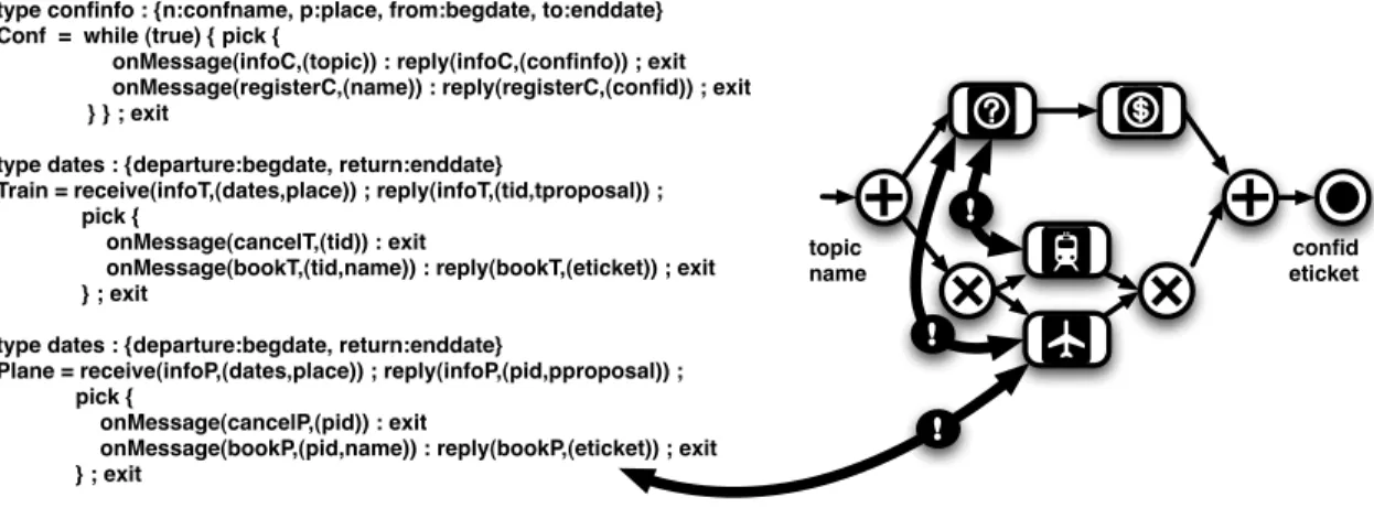
Further, services may present conversations. In such a case it is mandatory that the way the instantiated workflow uses the sub-services is compatible with their conversation. A typical example is given in Figure 1.10 where both services and composition require-ments present conversations. Further, services are described at the operation level, and requirements at the capability level. Here we have three services, Conf to get conference information (infoC) and perform registration (registerC), Train to get a possible train ticket (infoT) and then either book (bookT) or cancel (cancelT) it, and Plane to get a possible flight ticket (infoP) and then either book (bookP) or cancel (cancelP) it. The three services use both basic information types (e.g., place), and structured information types (e.g., confinfo). The service conversations have been given in ABPEL but they could also have been given as LTS or using some process algebra. The end-user request, given as a workflow,
type confinfo : {n:confname, p:place, from:begdate, to:enddate} Conf = while (true) { pick {
onMessage(infoC,(topic)) : reply(infoC,(confinfo)) ; exit onMessage(registerC,(name)) : reply(registerC,(confid)) ; exit } } ; exit
type dates : {departure:begdate, return:enddate}
Train = receive(infoT,(dates,place)) ; reply(infoT,(tid,tproposal)) ; pick {
onMessage(cancelT,(tid)) : exit
onMessage(bookT,(tid,name)) : reply(bookT,(eticket)) ; exit } ; exit
type dates : {departure:begdate, return:enddate}
Plane = receive(infoP,(dates,place)) ; reply(infoP,(pid,pproposal)) ; pick {
onMessage(cancelP,(pid)) : exit
onMessage(bookP,(pid,name)) : reply(bookP,(eticket)) ; exit } ; exit topic name confid eticket ! ! !
Figure 1.10: Composition in presence of conversations – inputs
expresses that conference related issues (first getting information, then registering) and transportation issues (either train or plane ticket reservation) can be done in parallel. Here we are in presence of horizontal mismatch: if getting conference information is performed at the same time than transportation booking, the date and place information will not be available. Further mismatch is due to the different structuring for these informations, e.g., place and date information in Conf and Train (resp. Plane). We are also in presence of vertical mismatch: while services define operations (e.g., bookP in Plane), the requirement uses capabilities (e.g., plane booking).
Process-1 = receive(USER,(topic,name)) ; invoke(Conf.infoC,(topic),(confinfo)) ; flow { invoke(Conf.registerC,(name),(confid)) ; exit, place := confinfo.p ; dates.departure := confinfo.from ; dates.return := confinfo.to ; invoke(Train.infoT,(dates,place),(tid,tproposal)) ; invoke(Train.bookT,(tid,name),(eticket)) ; exit } reply(USER,(confid,eticket) ; exit Process-2 = receive(USER,(topic,name)) ; invoke(Conf.infoC,(topic),(confinfo)) ; flow { invoke(Conf.registerC,(name),(confid)) ; exit, place := confinfo.p ; dates.departure := confinfo.from ; dates.return := confinfo.to ; invoke(Plane.infoP,(dates,place),(pid,pproposal)) ; invoke(Plane.bookP,(pid,name),(eticket)) ; exit } reply(USER,(confid,eticket) ; exit
Figure 1.11: Composition in presence of conversations – outputs
The outputs of an automated composition process should look like Figure1.11. The two possible compositions respect the control flows expressed in services and in the requirements, while ensuring a consistent data flow from the user inputs to the required outputs (using service outputs also when needed) and solving mismatch out.
The existence of service and composition requirement conversations, together with horizontal and vertical mismatch require complex composition algorithms. A solution is to include adaptation features in these algorithms.
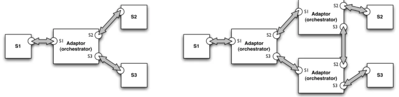
at the different interface description levels that prevents them from being composed. Solving such mismatch out is the objective of software adaptation [Seguel et al., 2008], or adaptation for short. Adaptation consists in building automatically one (orchestration) or several (distributed orchestration) software pieces called adaptors restoring compatibility in a non intrusive way (Fig.1.12, where bullets denote any kind -provided or required- of interface). S1 S2 S3 Adaptor (orchestrator) S2 S3 S1 Adaptor (orchestrator) S2 S3 S1 Adaptor (orchestrator) S2 S3 S1 S1 S2 S3 Adaptor (orchestrator) S2 S3 S1
Figure 1.12: Centralized vs. distributed adaptation
Adaptation differentiates due to its dynamic, non intrusive, and automatic nature, with techniques such as evolution [Mens and Demeyer, 2008] that assumes that the reused pieces of code may be modified, or software product lines [Pohl et al., 2005] that assume that the possible use contexts or variations of a reusable component have been envi-sioned. Adaptation should also not be confused with adaptive middleware [Agha, 2002], that provides the technical means to adapt, and do not tackle the semi-automatic or automatic generation of the adaptor model(s) and code. Finally, adaptation is also some-times compared in its objective with controller synthesis [Wonham and Ramadge, 1987,
Ramadge and Wonham, 1989]. The main differences are that adaptors can perform
mes-sage renaming, can reorder mesmes-sages, and support the data associated to mesmes-sages. Let us take two simple services: a client C and a server S. Different kinds of behavioral mismatch may happen:
• Name mismatch (or 1-1 mismatch): an operation provided by S and an operation required by C have the same semantics but have different names, e.g., two one-way operations, sendToPrinter and print.
• Unanticipated reception (or 1-0 mismatch): C tries to send a message to S while it is not used or required by it, e.g., C, in non-connected mode, tries to send a login/password before each request, while S, in connected-mode, requires it only once.
• Generalized mismatch (or n-m mismatch): C and S use a different number of operations/messages for some task, e.g., C wants to add two numbers x and y invoking in turn operations setX (to set x), setY (to set y) and add (to compute the sum) while S has a single operation, addition (to provide operands and compute the
sum at once). In this generalized mismatch, data may have to be aggregated (n-1) or split (1-n) amongst messages.
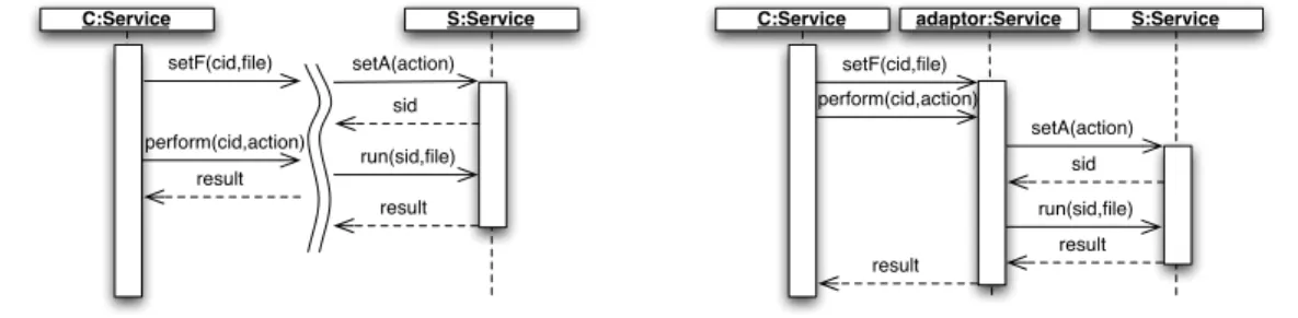
• Reordering: C and S have corresponding operations but different orderings, e.g., C first sets up a file to operate on (setF) and then asks for an operation to be performed on it (perform), while S has first an operation for setting up the action (setA) and then an operation for doing the previously set action on a given file (run).
C:Service S:Service setF(cid,file) perform(cid,action) result setA(action) run(sid,file) sid result C:Service S:Service setF(cid,file) perform(cid,action) result setA(action) run(sid,file) sid result adaptor:Service
Figure 1.13: Mismatch between services (left) and adaptor (right)
These different kinds of mismatch are illustrated on a simple example, Figure1.13, left, where the reordering case above is extended with new elements that will demonstrate how an adaptor works. C sends session identifiers (cid) with its messages to enable message follow-up. S also requires session identifiers to operate (sid), but these are generated by S and are different from the ones sent by C. As one can see from the figure, there is no chance that S can be used to fulfill the needs of C.
Adaptation techniques aim to automatically generate new components called adaptors, and may rely on an adaptation contract, which is an abstract description of how mismatches can be worked out. This is usually a morphism relating operations in the signatures interfaces of the adapted services. All the messages pass through the adaptor, which acts as an orchestrator and makes the involved services work correctly together by compensating mismatches. For instance, in the case of the name mismatch presented above, the adaptor would receive sendToPrinter from C and then would send print to S with the same data. If an unanticipated reception occurs, the solution is that the adaptor receives all client connection messages but only transmits the first one. In case of a generalized mismatch or a reordering issue, the adaptor would first receive from C all the necessary data and messages, and would interact with S only once all have been received. This is demonstrated on our example in Figure1.13, right.
Adaptation is mainly about restoring compatibility, hence avoiding the deadlocks that are the consequence of mismatch between service protocols. For this, adaptation can be restrictive, forbidding interactions between services leading to deadlocks, and/or generative, renaming and reordering messages to avoid deadlocks.
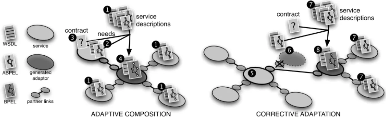
Still, adaptation also fosters services composition in-the-large. Adaptation can be used in a bottom-up process (Fig.1.14, left). Given services to be reused (1) and the composition requirement expressed as an additional service interface (2), adaptation generates, possibly
contract service descriptions ADAPTIVE COMPOSITION contract needs service descriptions CORRECTIVE ADAPTATION 1 2 1 5 1 6 service generated adaptor partner links WSDL BPEL ABPEL 1 1 1 1 1 1 1 4 ? 1 8 ? 1 7 1 7 1 3 1 1 71
Figure 1.14: Using adaptation to empower service composition
with the help of an adaptation contract (3), a centralized adaptor under the form of an orchestrator (4). Adaptation can also be used when one service fails at run time or more simply when one wants to replace a sub-service in a composition (Fig.1.14, right). Given the interface of the service to be replaced (6) and a set of replacement services (7), adaptation generates an adaptor between the client(s) of the replaced service and the replacement services (8).
Testing. The composition and adaptation processes are based on a key element: interfaces. It is therefore crucial to ensure that a service really does what it publicizes, and, as we have seen above, if a composition presents mismatch or not. Verification support this. Still, one has to face two important limits. First, the source code of services is not available (black-box assumption): only interfaces are published, and they usually describe much less than design artifacts. The second limit is related to the loosely-coupled and dynamic nature of service compositions. End-user requirements and services used to realize them may be known only at deployment or run time. Model-checking and behavioral equivalence techniques are of great interest during the design process to ensure for example that requirements correspond to what is really wanted, or that architectures known at design time are correct. However, with compositions being constructed at deployment time (end-user composition) and evolving dynamically, model based testing is required.
In active testing, the tester interacts with the implementation under test (IUT) by sending inputs (messages) and observing outputs (messages too). This method assumes a kind of controllability of the implementation through Points of Control and Observations (PCOs). Observing the outputs and comparing them to the expected ones, i.e., those described by the specification, a verdict can be emitted. A pass verdict establishes the conformance of the implementation to its specification and a fail verdict yields the opposite. Passive testing is a software testing method that relies only on observations on the running IUT. In passive testing the tester does not send messages to the IUT. It only observes the exchange (sending and reception) of messages between the IUT and its partners, through Points of Observation (POs). These observations will be compared to the specification in order to emit a verdict. The term “passive” relates to the fact that the tests do not disturb the natural operation of the IUT, to the contrary of “active” testing. Passive testing is of
particular interest since one does not always have the ability to control an IUT, especially after deployment (Fig.1.15).
execution
in the small
in the large chapter 2
chapter 3 deployment
development
active testing
verification passivetesting
Requirements Model Model Implementation Model Implementation
Figure 1.15: Verification (at design time), active and passive testing
Development as a continuous process. Service composition is today largely a static affair, as stated in [Papazoglou and van den Heuvel, 2007]. Due to user mobility, net-work problems, deprecation, etc. the services being used in a composition may be-come unusable, while other ones may appear. In a context of end-user composition, that is the automatic composition to fulfill on-demand user needs, these needs may also evolve. These issues are at the core of new highly dynamic and adaptive sys-tems [Cheng et al., 2008,Bernardo and Issarny, 2011]. In this context, composition should be thought as a dynamic and continuous process (Fig. 1.16).
execution
in the small
in the large chapter 2
chapter 3 deployment development passive testing monitoring end-user composition adaptation active testing verification composition adaptation repair adaptation
Figure 1.16: Activities in a continuous composition process
Here, a composition results either from an usual enterprise design (including composition, verification at design time, and active testing steps before publication) or as an end-user
request fulfillment. At run time, passive analysis techniques are to be used to check the correctness of the composition with reference to its dynamic environment. This can be done using monitoring or testing. In case of a problem, yielding a broken composition, corrective measures should be taken (using online adaptation and repair) to yield a new composition.
In my work I propose formal techniques for the composition, adaptation, testing (both active and passive), and repair of composite systems. As such, I try to enable this new vision of composition as a continuous process.
1.4
General Principles
For proposing solutions to the software engineering issues presented in the previous section, I defend and I have followed some interrelated general principles:
• (P1) importance of formal models • (P2) absence of universal formal model.
• (P3) use of a layered formal model transformation approach. • (P4) importance of behavioral interfaces.
• (P5) automation of the solutions and tool support. • (P6) connection with the applicative domain.
(P1) importance of formal models. Formal methods promote the development of well-founded solutions and their automation. Further, using formal methods for software engineering issues enables one to reuse not only the related theory, but also to gain tool-support. The Model Driven Engineering (MDE) paradigm, that has now emerged in software engineering, is also calling for formal models as demonstrated for example in [Combemale et al., 2009] where the use of bisimulation theory enables to ensure correct-ness of model transformations. Still, the use of formal models in MDE and the seamless integration of activities supported by formal methods in the software development pro-cess could be further developed, as proposed, e.g., in [Kordon et al., 2008] for verification activities, switching from MDE to Verification Driven Engineering (VDE).
(P2) absence of universal formal model. It is known that there is no universal language or model. It would be so expressive that its complexity would prevent developing any practical solution on it. This complexity would anyway also prevent its use by non specialists, e.g., non academic software architects or end-users. Rather, specific languages or models should be used, i.e., defined or reused, for specific applicative domains (here, composite systems) and specific issues (composition, adaptation, verification).
(P3) use of a layered formal model transformation approach. Having languages and models being specific for applicative domains and for issues yields not only domain specific languages (and models) but also issue specific working languages (and models).
This promotes the development of a layered approach based on different languages and models, and on model transformations (Fig.1.17).
ENCODING Input Domain Language DLin Output Domain Language DLout Input Domain Model DMin Output Domain Model DMout Input Working Model WMin Output Working Model WMout Input Working Language WLin Output Working Language WLout Working Tool (ad-hoc or reused) DO M A IN S P E C IF IC DO M A IN A N D IS SU E S P E C IF IC
Figure 1.17: Layered formal model transformation approach
The left hand part of the figure is relative to the issue and the right hand part to the solution (if it exists). Taking domain specific inputs (e.g., a service composition requirement language), one retrieves models for them (e.g., one of those presented in the next section). This model is transformed using an encoding into another model that is suitable for an issue of interest (e.g., some planning structure for automated composition). This model is then dump in a language that is understood by some ad-hoc or reused tool. Once the tool has run, one proceeds the other way round, reading the tool outputs, transforming them in some domain specific model (e.g., an orchestration formal model) and finally in some domain specific language (e.g., the BPEL orchestration language). This architecture promotes the reuse of domain language from/to domain model transformations (e.g., (A)BPEL from/to STS) in different issue contexts. Still, this does not prevent that domain and working models coincide. This architecture shares some of its objectives with VDE [Kordon et al., 2008], having formal activities at the core of the software development process, with different tailored models and techniques to be used for different properties and at different steps of this process.
(P4) importance of behavioral interfaces. We have seen that components (including services) could be described at four different interface description languages. Industrial models and languages by using signature level interfaces and middleware are able to solve technical issues such as component heterogeneity. However, the behavioral description level is essential because even if components match from a signature point of view, their combination can lead to deadlocks or erroneous situations if one is not aware of their execution flows and does not take them into account while building the systems.
(P5) automation of the solutions and tool support. The manual application of engineering principles is tedious and error prone. In order to be applicable, the proposed solutions should go beyond proposing notations, patterns, or structuring rules to be applied by the software architect. These solutions should be automated, which, further, paves the way for on-demand composition by end-users and self-corrective systems. Automation includes the development of prototype tools in order to validate empirically the solutions. (P6) connection with the applicative domain. New applicative domains such as SOA
promote initially approaches that address domain specific issues in a very abstract and theoretical way. This is valuable to ease the application of principle P1. However, models are also there to model and address questions on some reality. Proposing solutions for the development of composite systems without connecting them to any real-life composition framework would be somehow stopping half-way. First, software engineering is about software. One cannot therefore develop a software engineering technique without addressing the relation with software in some sense, e.g., relating standard requirement languages with formal models, orchestration models with execution languages, or passing test cases using SOAP rather than just generating abstract test cases. Second, practical implementations bring additional issues, e.g., the role of BPEL engines in the execution semantics of an orchestration, that should be taken into account to assess proposed formal solutions.
1.5
Preliminary on Formal Models
In my work, I have used different formal models. In this section I briefly present them. This can be skipped in a first reading and serve as a background complement for concepts and techniques used in the contributions presented in Chapters2 and 3.
Events. Events are the base building block of a behavioral description. Therefore, the first step in developing a behavioral formal approach for software engineering is to define the set of events. As far as software architectures and their service instantiation presented above are concerned, events fall in one of the following categories:
• interaction events are relative to the interaction between components in a configura-tion (or composite component). For a message based implementaconfigura-tion (Web services), these events correspond to the sending and the receiving of a message m (input or output) relative to some operation o in some partnerlink p. Hence, such events are denoted with Evcomm= Evin∪ Evout, where events in Evin (inputs) are of the form
between operations and messages is clear from the context (it can be inferred from the signature/WSDL file) one can use only p.o? and p.o!, or m? and m!.
• the internal event, τ, is used to denote internal actions of components (e.g., assign-ment) or of composites (e.g., internal interactions between sub-components not being observable from outside).
• the termination event, √, is used to denote the correct termination of a process and differentiate from deadlock situations.
• the time passing event, χ, is used to model a discrete version of time (time constraints of a Web service are generally soft, thus such a discretization of time is a valid abstraction [Haddad et al., 2004a]).
The set of events used in behavioral formal models may then be defined as Ev = Evcomm∪ {τ,√, χ}
Depending on the abstraction level, e.g., mainly in our context whether data associated to messages are taken into account or not, interaction events may support additional variables (e.g., for message formal parts in message reception, p.o.m?x, y) or values (e.g., for message effective values in message sending, p.o.m!”Hello”, 123). For some given formal model representing a component or a behavioral interface, its set of events, included in Ev, is also called alphabet.
Trace Sets (TSet). A trace is used to denote a sequence of events, and a trace set is simply a set of traces. Without entering the battle between linear vs. branching models and logics [Vardi, 2001], trace sets are used mainly in relation with an implementation, in which a given sequence of events has happened (hence where branching is not needed), i.e., logs.
Definition 1.5.1 (Trace). Given an alphabet A, a trace t is a word on A, i.e., t∈ A∗. A trace on A is usually denoted ha1, . . . , ai, . . . , ani, with ai ∈ A for each ai, and hi
denotes the empty trace. One is often interested in prefix-closed trace sets, which are sets of traces T such that∀ha1, . . . , ai, . . . , an−1, ani ∈ T ha1, . . . , an−1i ∈ T . Operator . (resp.
_) denotes event/trace (resp. trace/trace) concatenation.
Labeled Transition Systems (LTSs). State transition models have the benefit to combine formalism and user-friendliness. This is the reason why that are often used in industry, with, e.g., UML state diagrams. Labeled Transition System (LTSs) are a simpler version of these, without expressive structuring mechanisms such a hierarchical or parallel states. LTSs can be found under different names with small variations, mainly in the supported events and their structuring (or not) as inputs and outputs, and in the product definitions. The LTSs we use originate from the seminal work by Arnold [Arnold, 1994]. A major interest of LTSs is tool support. Another interest of LTSs is that they can be retrieved using the operational semantics of various other formal models, such as process algebras, event structures, and Petri nets.