HAL Id: hal-01694219
https://hal.archives-ouvertes.fr/hal-01694219
Submitted on 14 Apr 2018HAL is a multi-disciplinary open access archive for the deposit and dissemination of sci-entific research documents, whether they are pub-lished or not. The documents may come from teaching and research institutions in France or abroad, or from public or private research centers.
L’archive ouverte pluridisciplinaire HAL, est destinée au dépôt et à la diffusion de documents scientifiques de niveau recherche, publiés ou non, émanant des établissements d’enseignement et de recherche français ou étrangers, des laboratoires publics ou privés.
An effective low-temperature solution synthesis of
Co-doped [0001]-oriented ZnO nanorods
Hatim Alnoor, Adrien Savoyant, Xianjie Liu, Galia Pozina, Magnus
Willander, Omer Nur
To cite this version:
Hatim Alnoor, Adrien Savoyant, Xianjie Liu, Galia Pozina, Magnus Willander, et al.. An effective low-temperature solution synthesis of Co-doped [0001]-oriented ZnO nanorods. Journal of Applied Physics, American Institute of Physics, 2017, 121 (21), �10.1063/1.4984314�. �hal-01694219�
An effective low-temperature solution synthesis
of Co-doped [0001]-oriented ZnO nanorods
Hatim Alnoor, Adrien Savoyant, Xianjie Liu, Galia Pozina, Magnus Willander and Omer Nur
The self-archived version of this journal article is available at Linköping University Electronic Press:
http://urn.kb.se/resolve?urn=urn:nbn:se:liu:diva-138890
N.B.: When citing this work, cite the original publication.
Alnoor, H., Savoyant, A., Liu, X., Pozina, G., Willander, M., Nur, O., (2017), An effective low-temperature solution synthesis of Co-doped [0001]-oriented ZnO nanorods, Journal of Applied
Physics, 121(21), . https://dx.doi.org/10.1063/1.4984314
Original publication available at:
https://dx.doi.org/10.1063/1.4984314
Copyright: AIP Publishing
1
An effective low-temperature solution synthesis of Co-doped [0001]-oriented
ZnO nanorods
Hatim Alnoor, 1, a) Adrien Savoyant, 2 Xianjie Liu, 3 Galia Pozina, 3 Magnus Willander, 1 and Omer Nur1 1 Department of Science and Technology (ITN), Linköping University, SE-601 74 Norrköping, Sweden 2 IM2NP, CNRS UMR 7334, FST, Aix-Marseille Université, F-13397 Marseille Cedex 20, France
3 Department of Physics, Chemistry, and Biology (IFM), Linköping University, SE-583 81 Linköping, Sweden Abstract
We demonstrate an efficient possibility to synthesize vertically aligned pure zinc oxide (ZnO) and Co-doped ZnO nanorods (NRs) using the low-temperature aqueous chemical synthesis (90 ºC). Two different mixing methods of the synthesis solutions were investigated for the Co-doped samples. The synthesized samples were compared to pure ZnO NRs regarding the Co incorporation and crystal quality. Electron paramagnetic resonance (EPR) measurements confirmed the substitution of Co2+ inside the ZnO NRs giving a highly anisotropic magnetic Co2+
signal. The substitution of Zn2+ by Co2+ was observed to be combined with a drastic reduction in
the core-defect (CD) signal (g ~ 1.956) which is seen in pure ZnO NRs. As revealed by the cathodoluminescence (CL) the incorporation of Co causes a slight red-shift of the UV peak position combined with an enhancement in the intensity of the defect-related yellow-orange emission compared to pure ZnO NRs. Furthermore, the EPR and the CL measurements allow a possible model of the defect configuration in the samples. It is proposed that the as-synthesized pure ZnO NRs likely contain Zn interstitial (Zni+) as CDs and oxygen vacancy (VO) or oxygen interstitial
(Oi) as surface defects. As a result, Co was found to likely occupy the Zni+ leading to the observed
CDs reduction, and hence enhancing the crystal quality. These results open the possibility of synthesis of highly crystalline quality ZnO NRs-based diluted magnetic semiconductors (DMSs) using the low-temperature aqueous chemical method.
Keywords: Low-temperature aqueous chemical synthesis, ZnO NRs, Co-doping, EPR, intrinsic
point defects.
2 1- Introduction
Zinc Oxide (ZnO) is a direct wide band gap (3.4 eV at room temperature) semiconductor with a relatively large exciton binding energy of 60 meV and possesses a significant luminescence covering the whole visible region.1-4 Moreover, ZnO can be easily synthesized in a diversity of one-dimensional (1D) nanostructure morphologies on any substrate being crystalline or amorphous. 1-7 In particular, 1D ZnO nanostructures such as nanowires (NWs) and nanorods (NRs) have recently attracted considerable research due to their potential for the development of many optoelectronic devices, such as light-emitting diodes (LEDs), ultraviolet (UV) photodetectors and solar cells.2-4,8-10 Also, ZnO NRs-based diluted magnetic semiconductors (DMSs), where a low concentration of magnetic elements (such as manganese (Mn) and cobalt (Co)) is diluted in the ZnO crystal lattice, show great promise for the development of spintronics and magneto-optical devices.11-14 Among the different synthesis techniques utilized for ZnO NRs, the low-temperature
solution-based methods are promising due to many advantages, i.e., low-cost, large-scale production possibility and the properties of the final product can be varied by tuning the synthesis parameters.5-7 However, synthesizing ZnO NRs with optimized morphology, orientation, electronic
and optical properties by low-temperature solution-based methods remains a challenge. The potential of ZnO NRs in all above-mentioned applications would require synthesis of high crystal quality ZnO NRs with controlled optical and electronic properties.2-4,15 It is known that the optical and electronic properties of ZnO NRs are mostly affected by the presence of the native (intrinsic) and impurities (extrinsic) defects.1-4 Therefore, understanding the nature of these intrinsic and extrinsic defects and their spatial distribution is critical for optimizing the optical and electronic properties of ZnO NRs.1-4,16-18 However, identifying the origin of such defects is a complex matter, especially in nanostructures, where the information on anisotropy is usually lost due to the lack of coherent orientation. Recently, we have shown that by optimizing the synthesis parameters such as stirring times and the seed layer properties, the concentration of intrinsic point defects ( i.e. vacancies and interstitial defects ) along the NRs and at the interface between the NRs and substrate can significantly be tuned.8,19,20 Thus, the ability to tune such point defects along the NRs could further enable the incorporation of Co ions where these ions could occupy such vacancies through substitutional or interstitial doping, e.g. a Co ion can replace a Zn atom or be incorporated into interstitial sites in the lattice.21 Here, by developing theses synthesis methods, we obtained well-oriented ZnO NRs, and by studying them at low temperature, we can access the magnetic
3
anisotropy of such defects. Furthermore, by incorporating a relatively low amount of diluted Co into ZnO NRs the crystal structure of the as-synthesized well-oriented ZnO NRs can significantly be improved. The well-oriented pure ZnO and Co-doped ZnO NRs were synthesized by the low-temperature aqueous chemical synthesis (90 ºC). The structural, optical, electronic, and magnetic properties of the as-synthesized well-oriented NRs have been systematically investigated by mean of field-emission scanning electron microscopy (SEM), X-ray powder diffraction (XRD), electron paramagnetic resonance (EPR), cathodoluminescence (CL) and X-ray photoelectron spectroscopy (XPS).
2- Experimental
The pure ZnO and Co-doped ZnO NRs were synthesized by the low-temperature aqueous chemical synthesis at 90 ºC on sapphire substrates. For pure ZnO NRs, a 0.075 M synthesis solution was prepared by dissolving hexamethylenetetramine (HMTA) and zinc nitrate hexahydrate in a deionized (DI) water and then stirred for three hours at room temperature (later denoted as M0 sample). After that, a sapphire substrate precoated with ZnO seed layer,8,19,20 were submerged horizontally inside the above-mixed solutions and kept in a preheated oven at 90 °C for 5 hours. Afterward, the samples were rinsed with DI-water to remove any residuals and finally, dried using blowing nitrogen. The synthesis process of the pure ZnO NRs is described in more details in
Ref.8,19,20
The Co-doped ZnO NRs were grown under similar conditions where two different approaches were used to prepare the synthesis solution. The first synthesis solution was prepared by mixing a 0 .075 M concentration of HMTA and zinc nitrate and stirred for 15 hours. Then a diluted solutions of Cobalt(II) nitrate hexahydrate with an atomic concentration of 7% was added dropwise to the above solution and stirred for extra 3 hours (later denoted as M1). The second synthesis solution was prepared by mixing a 7% diluted solution of Cobalt(II) nitrate hexahydrate with 0.075 M HMTA and stirred for 15 hours, and then a 0.075 M solution of zinc nitrate hexahydrate was added dropwise to the above-mentioned solution and stirred for extra 3 hours (later denoted as M2).
The morphology of the as-synthesized pure ZnO and Co-doped ZnO NRs was characterized using field-emission scanning electron microscopy (FE-SEM, Gemini LEO 1550). The crystalline and electronic structure were investigated by XRD using a Philips PW1729 diffractometer
4
equipped with Cu-Kα radiation (λ = 1.5418 Å) and EPR, respectively. The EPR measurements were performed using a conventional Bruker ELEXSYS continuous wave spectrometer operating at X-band (ν = 9.38 GHz) equipped with a standard TE102 mode cavity. The angle between the
static magnetic field and the NRs axis, denoted by θ, was monitored by a manual goniometer. The optical properties were examined by cathodoluminescence (CL) using Gatan MonoCL4 system combined with Gemini LEO 1550 FE-SEM. The CL measurements were performed on aggregated nanorods using an acceleration voltage of 5 kV. The chemical composition was analyzed by XPS measurements recorded by Scienta ESCA-200 spectrometer using monochromator Al Kα X-ray source (1486.6 eV). All the measurements were carried out at room temperature (RT) except the EPR measurements which were performed at 6 K.
3- Results and discussion
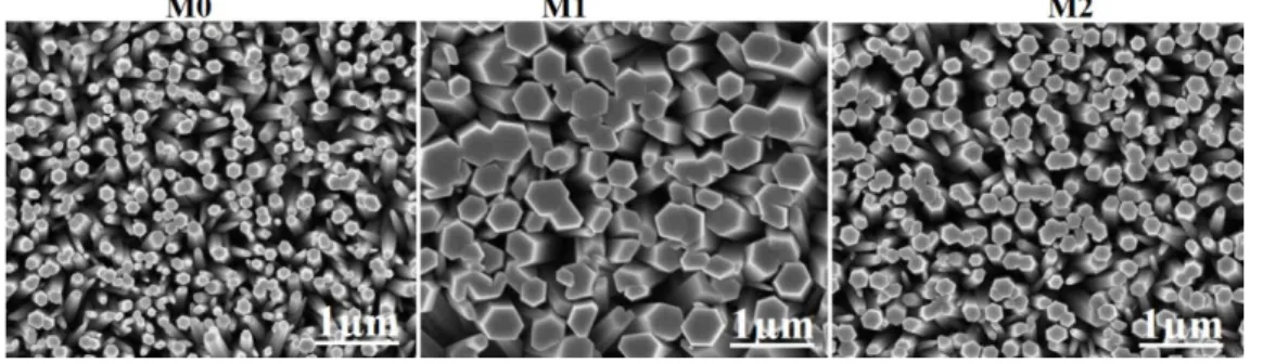
Fig. 1 shows the top-view FE-SEM images of the as-synthesized pure ZnO (M0) and Co-doped ZnO NRs (M1) and (M2), respectively. The SEM images reveal that all the as-synthesized NRs were vertically-aligned with a hexagonal shape. The average diameter of the NRs was found to be ~160, ~400 and ~200 nm, for the M0, M1, and M2, respectively. The significant and slight increase in NRs average diameter in the case of M1 and M2 compared to M0 is likely due Co doping.22,23
Fig. 1: SEM images of pure ZnO (M0) and Co-doped ZnO NRs as-synthesized using approaches M1 and M2, respectively.
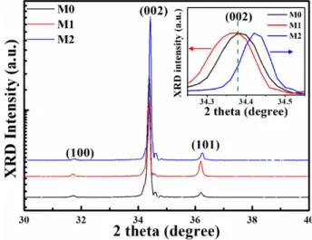
The structural quality of the as-synthesized pure ZnO and Co-doped ZnO NRs have been confirmed by the XRD measurements as illustrated in Fig. 2. The XRD patterns showed that all the as-synthesized samples have a wurtzite structure and possess a good crystal quality with preferred growth orientation along the c-axis, as demonstrated by the intensity of the (002) peak.15,23-25 Also,
5
three NRs samples. As shown in the inset of Fig. 2 the position of the (002) peak is slightly shifted toward lower 2θ angle in M1, and toward higher 2θ angle in M2 as compared to M0. The peak position shift toward lower and higher 2θ angle are reported to be a confirmation of the successful incorporation of Co into the ZnO crystal lattice.15,23,26 Also, the peak position shift is reported to be due to the variation of oxygen vacancies (Vo) and zinc interstitials (Zni) caused by
Co-doping.27,28 In this study, the Co concentration in the synthesis solution is the same (7 %) for both M1 and M2. Thus, the observed shifts in the peak position could be attributed to either Co incorporation or to the variation of the defects concentration, e.g. such as vacancies and interstitials induced by Co doping. These results show that the way of preparing the synthesis solution have a significant influence on the Co incorporation in the synthesized ZnO NRs.
Fig. 2: XRD patterns of the as-synthesized pure ZnO (M0) and Co-doped ZnO NRs (M1 and M2). The inset shows the normalized XRD data for the (002) peaks, indicating peak shifts.
Further, to confirm the crystal quality and the incorporation of Co into the ZnO crystal lattice as suggested by the XRD results, EPR spectra were recorded at 6 K, and the results are shown in Fig. 3 (a)-(b). The EPR spectra of pure ZnO NRs (M0) is characterized by the well-known defect signal from ZnO apparent at 350 mT (g ~1.956) 29-34 as shown in Fig. 3 (a),and commonly attributed to core-defects (CDs) arising from ZnO nanostructures rather than shell defects.32,33 However, the identification of the exact nature of this CDs (1.956) signal is controversial,35 and up to date, no experiment can give a concerete answer. Previously, many defect signals close to this value (1.956) have been reported and Zn interstitials (Zni+) and the so-called D* center were proposed.31,34
6
magnetic anisotropy and are composed of two overlapped lines. This observed anisotropy is compatible with a Zni+ defect (easy-axis) but not with D* defect (easy plane), so that Zni+ appears
to be the most probable defect.31,34 In our previous study, these CDs were characterized by three lines, which supports our hypothesis that these lines are likely a variation of the same defect, i.e. the same defects with slightly different parameters.36 The successful substitution of Co2+ was confirmed by the observed Co-related signal characterized by an eight-lines structure at g ~ 2.239 (θ = 0º ) and a broad asymmetric signal at g ~ 4.517 (θ = 90º ),21,36,37 as shown in Fig. 3 (b). The observed magnetic anisotropy of the Co2+ signal is a clear indication that the as-synthesized NRs are single crystalline,well-aligned and that Co is highly diluted along the NRs.36 Interestingly, the substitution of Co2+ caused a drastic reduction of the CD signal (g ~1.956) as indicated by dashed line (Fig. 3(b)) compared to that in the pure ZnO NRs (M0) (as shown Fig. 3 (a)), as previously observed in similar samples.36 In fact, this could suggest that a certain amount of the incorporated
Co is involved in the CDs neutralization. This neutralization could be due to substitutional doping, where a Zn atom is replaced by a Co atom (Cozn), or to interstitial doping, where a Co atom is
incorporated into interstitial sites in the lattice (Coi).21 As shown in Fig. 3(b) the intensity of the
Co2+ signal of M2 at θ = 90º and θ = 0º is significantly higher as compared to that of M1. Moreover,
the line width of the Co2+ signal at θ = 0º for M2 is found to be a slightly smaller (4 G) than that of M1(5 G). As the Co concentration in the synthesis solution is the same (7 %) for both M1 and M2, and by assuming a uniform doping and same coverage of the NRs, these results clearly show that the way of preparing the synthesis solution have a significant influence on the Co incorporation in the synthesized ZnO NRs in agreement with the XRD results shown in Fig. 2. It should be noted that the hyperfine constant (the spacing between two hyperfine line) is ~15.3 G in both samples, that is the same value for the bulk Co-doped ZnO.36 Thus, we can deduce that the observed EPR signal comes from the substitutional Co2+ inside the NRs, and not from ions on the surface. However, such an observation did not make exclusive evidence that the presences of Co is on the surface of the as-synthsized Co-doped ZnO NRs. In the solution-based synthesis method, it is possible that Co2+ can be incorporated in the core of ZnO nanostructures or can be adsorbed at their surface.21
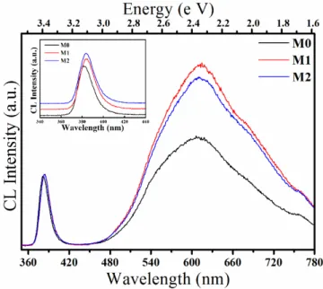
Furthermore, in order to get more information on the defects in the as-synthesized pure ZnO and Co-doped ZnO NRs, room-temperature CL spectra were carried out, and the results are shown in Fig. 4. The emission spectra of all samples were dominated by UV emission peak centered at
7
~382 nm (3.24 eV) due to near-band-edge (NBE) emission and a strong broad yellow-orange emission centered at ~ 610 nm (2.03 eV) associated with deep-level defects related emission in
ZnO.1-4,38-40
Fig. 3: (a) EPR spectra show anisotropy of the CD signal in the pure ZnO sample (M0). (b) EPR spectra of Co-doped ZnO NRs ( M1 and M2 ) for parallel (θ = 0º) and perpendicular (θ = 90º) orientation of magnetic field, recorded at T = 5 K. The upper axis gives corresponding g factor values.
Apparently, the CL spectra of Co-doped NRs exhibited a small red-shift of the UV peak position from 382 nm to 384 nm (as shown in the inset of Fig. 4) as compared to pure ZnO NRs, which is likely due to the change in the energy of the band structure as a result of doping.22,41 It is important to note that the CL defect-related yellow-orange emission intensity decreases from M1 to M2 (Fig. 4) and the Co EPR signal increases from M1 to M2 (Fig. 3 (b)). This observation suggests that the way of preparing the synthesis solution have a significant influence on the Co incorporation and defect formation in the as-synthesized ZnO NRs in agreement with the XRD results shown in Fig. 2.
The physical origin of intrinsic defects-related yellow-orange emission is controversial, and it is proposed to be associated to the Vo, Oi and Zni.23,38-40 Recently, it was proposed that the
defects-related orange emission is to be likely from the Zni in the core of ZnO NRs.39 In this study,
8
core of ZnO NRs or the Vo and Oi on the surface of ZnO NRs. As a consequence, the intensity
of the defects-related yellow-orange emission is significantly enhanced by the Co doping (Fig. 4), which probably due to the increase in Vo and Oi in the NRs or to the Co-related defect.15,23,41
Moreover, this suggests the above-observed red-shift of the UV peak could be attributed to the variation of the Zni+ concentration in the Co-doped samples (M1 and M2) compared with the pure ZnO NRs (M0). In fact, these results indicate that the bulk quality of the ZnO NRs is improved by the substitution of Co, while the doping has the adverse effect on the surface defects related emission, in agreement with previous results.15,41
Fig. 4: CL spectra of the as-synthesized pure ZnO and Co-doped ZnO NRs synthesized using different synthesis preparation approaches as indicated. The inset shows the red-shift in the UV peak. For clarity, the spectra are normalized to the near band edge intensity.
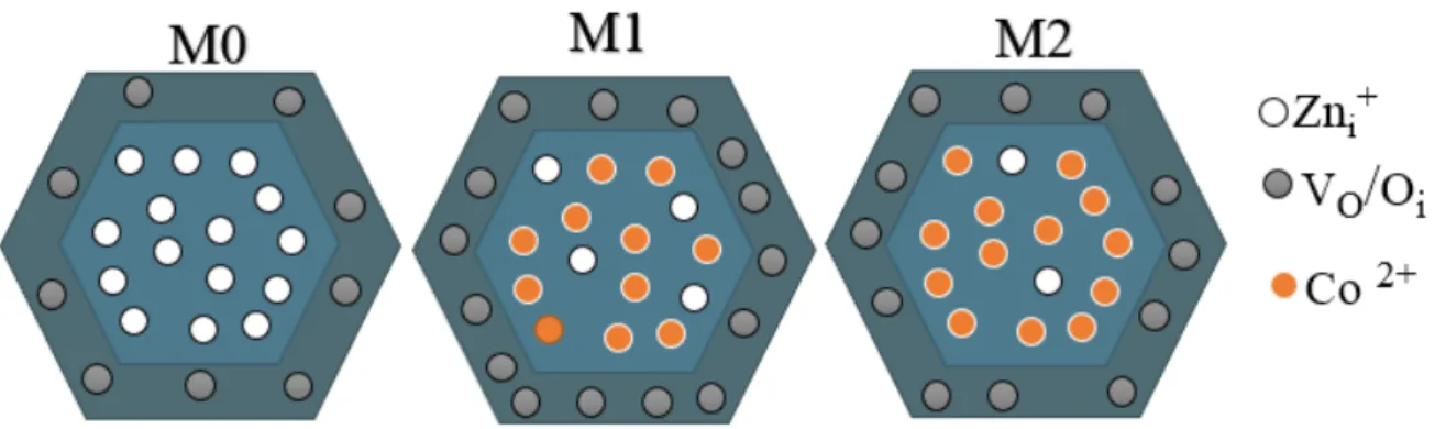
In view of the EPR and the CL results, a defect distribution model for ZnO NRs is shown in Fig. 5,32 which propose that the incorporation of Co during the synthesis process could probably result in occupying Zni+ through substitutional or interstitial doping and, subsequently, enhance
the crystal quality. The other possibility is that a substitutional Co2+ very close to a Zni+ interstitial
may form a non-magnetic complex, which is then not anymore EPR detectable. Also, the incorporation of Co was found to lead to the increase concentration of surface defects such as VO
and Oi. Further experimental study combined with detailed theoretical calculations are necessary
9
To elaborate more on surface related defect concentration, XPS spectra of all samples have been investigated. Figure 6 (a) shows the Zn 2p core level spectra of all samples, which is composed of two peaks centered at ~ 1022.2 and 1045.0 eV corresponding to binding energy lines of the Zn 2p3/2 and Zn 2p1/2, respectively, with a spin-orbital splitting of 23.1 eV suggesting that Zn is present
as Zn2+.22 Co signal in the ZnO NRs was not detected by the XPS; this could be attributed to the surface sensitive XPS technique with the Co2+ at the inner core of ZnO NRs, as indicated in Fig. 5, and also due to the low Co concentration, as suggested by the EPR measurements in Fig. 3 (b). The O1s core level peak for all samples exhibits an asymmetric profile, which can be decomposed into three Gaussian peaks, donated to OI, OII, and OIII, respectively, as shown in Fig. 6 (b). The OI peak
at low binding energy at ~530.9 eV is attributed to the Zn-O bond within the ZnO crystal lattice. Whereas the OII peak centered at ~532.2eV is commonly assigned to oxygen-deficiency in the ZnO
crystal lattice.16,42 Finally, the O
III peak centered at ~ 533.1 eV is related to the absorbed oxygen
on the ZnO surface, e.g. H2O, O2.16,42
Fig. 5: Schematic illustration of the cross-sectional view of the as-synthesized pure ZnO and Co-doped ZnO NRs containing Zni+ as core-defect and oxygen vacancies/interstitials as surface
defects, respectively.
The relative concentration of oxygen vacancies is estimated from the intensity ratios of OII/OI using the integrated XPS peak areas and the element sensitivity of the O and Zn.42 The ratios
of OII/OI were found to be 0.54, 0.52 and 0.49 for M0, M1, and M2, respectively, suggesting that
M2 has a lower concentration of oxygen vacancies compared to M1 and M0, respectively. However, there is no obvious relationship between the samples defect composition estimated from the CL and XPS measurements. For instance, M0 shows lower CL defect emission intensity and higher OII/OI ratio.
10
Fig. : XPS core level spectra of the (a) Zn 2p peak and (b) O 1s peak of the as-synthesized pure and Co-doped ZnO NRs as indicated.
4- Conclusions
The optical properties of ZnO NRs are commonly dominated by the presence of native intrinsic point defects, and identifying these defects is a difficult matter, especially in the nanostructure, where the information on anisotropy is usually lost due to the lack of coherent orientation. Here, by studying well-oriented ZnO NRs at low temperature, we were able to access the magnetic anisotropy of theses defects. Furthermore, by incorporating a relatively low amount of diluted Co inside ZnO NRs the crystal structure of the as-synthesized well-oriented ZnO NRs is significantly improved. Pure ZnO and Co-doped ZnO NRs were synthesized by the low-temperature aqueous chemical method, where the crystal structure, orientation, and incorporation of the Co ion is tuned by the preparation procedure of the synthesis solution. The SEM and XRD measurements showed that the as-synthesized pure ZnO and Co-doped ZnO NRs are vertically aligned along c-axis and have a wurtzite crystal structure of high quality, as demonstrated by the intensity of the (002) diffraction peak. Moreover, the (002) peak position was observed to be shifted to lower or higher 2θ angle depending on the synthesis solution mixing procedure used. This is probably attributed to either Co incorporation or to the variation of the defect concentration in the samples, e.g. such vacancies and interstitials induced by Co doping. EPR measurements have confirmed the substitution of Co2+ inside ZnO NRs giving a highly anisotropic magnetic Co2+ signal characterized by eight lines indicating that the as-synthesized NRs are single crystalline,
well-11
aligned and the Co is homogeneously distributed along the NRs. Also, the substitution of the Co2+ was observed to be accompanied by a drastic reduction in the CD signal (g ~ 1.956) found in pure ZnO NRs. As revealed by CL, the incorporation of Co causes a red shift in the UV peak position with an observed enhancement in the intensity of defect-related emission as compared to pure ZnO NRs. In view of the different results from these complementary measurements, we proposed that the as-synthesized pure ZnO NRs likely contain Zn interstitial (Zni+) as CDs and oxygen vacancy
(VO) or interstitial (Oi) as surface defects. These results open for the possibility of synthesis of
highly crystalline quality ZnO-based DMSs using the low-temperature aqueous chemical method.
Acknowledgement:
This work was supported by the NATO project Science for Peace (SfP) 984735, Novel magnetic nanostructures.
Reference
1 Ü. Özgür, Ya. I. Alivov, C. Liu, A. Teke, M. A. Reshchikov, S. Doğan, V. Avrutin, S.-J. Cho,
and H. Morkoç, J. Appl. Phys. 98, 041301 (2005).
2 M. Willander, O. Nur, Q. X. Zhao, L. L. Yang, M. Lorenz, B. Q. Cao, J. Zúñiga Pérez, C. Czekalla,
G. Zimmermann, M.Grundmann, A. Bakin, A. Behrends, M. Al-Suleiman, A. El-Shaer, A. Che Mofor, B. Postels, A. Waag, N. Boukos, A.Travlos, H. S. Kwack, J. Guinard, and D. Le Si Dang, Nanotechnology 20, 332001 (2009).
3 A. B. Djurišić, A. M. C. Ng, and X. Y. Chen, Progress in Quantum Electronics 34, 191 (2010). 4 S. Xu, and Z. L. Wang, Nano Res. 4, 1013 (2011).
5 L. Vayssieres, Adv. Mater.15, 464 (2003).
6 L. E. Greene, M. Law, D. H. Tan, M. Montano, J. Goldberger, G. Somorjai, and P. Yang, Nano
Lett.7, 1231 (2005).
7 A. Zainelabdin, S. Zaman, G. Amin, O. Nur, and M. Willander, Crystal Growth & Design 10,
12
8 H. Alnoor, G. Pozina, M. Willander, and O. Nur, Phys. Status Solidi A 214,1862 (2017).
9 C. O. Chey, X. Liu, H. Alnoor, O. Nur, and M. Willander, Phys. Status Solidi RRL 9,87 (2015). 10 M. Law, L. E. Greene, J. C. Johnson, R. Saykally, and P. Yang, Nat. Mater. 4, 455 (2005). 11 Z. Jin, T. Fukumura, M. KawasakiK. Ando, H. SaitoT. SekiguchiY. Z. Yoo, M. Murakami, Y.
Matsumoto, T. Hasegawa, and H. Koinuma, Appl. Phys. Lett. 78, 3824 (2001).
12 K. R. Kittilstved, W. K. Liu, and D. R. Gamelin, Nat. Mater. 5, 291 (2006).
13 P. Sharma, A. Gupta, K.V. Rao, F. J. Owens, R. Sharma, R. Ahuja, J. M. Osorio Guillen, B.
Johansson, and G. A. Gehring, Nat. Mater. 2, 673 (2003).
14 Z. H. Zhang, X. Wang, J. B. Xu, S. Muller, C. Ronning, and Q. Li, Nat. Nanotech. 4,523 (2009). 15 C.-W. Liu, S.-J. Chang, S. Brahma, C. –H. Hsiao, F. M. Chang, P. H. Wang, and K. Y. Lo, J.
Appl. Phys. 117, 084315 (2015).
16 E. De la Rosa, S. Sepulveda-Guzman, B. Reeja-Jayan, A. Torres, P. Salas, N. Elizondo, and M.
Jose Yacaman, J. Phys.Chem. C 111, 8489 (2007).
17 A. Janotti, and C. G. Van de Walle, Phys. Rev. B 76, 165202(2007).
18 L. J. Brillson, W. T. Ruane, H. Gao, Y. Zhang, J. Luo, H. von Wenckstern, and M. Grundmann,
Materials Science in Semiconductor Processing 57, 197 (2017).
19 H. Alnoor, C. O. Chey, G. Pozina, X. Liu, V. Khranovskyy, M. Willander, and O. Nur, AIP
Advances 5, 087180 (2015).
20 H. Alnoor, C. O. Chey, G. Pozina, X. Liu, V. Khranovskyy, D. Iandolo, M. Willander, and O.
Nur, J. Appl. Phys. 119, 165702 (2016).
21 P .Lommens, F . Loncke, P.F. Smet, F . Callens, D. Poelman, H . Vrielinck, and Z. Hens, Chem.
Mater. 19, 557(2007).
22 B. Panigrahy, M. Aslam, and D. Bahadur, J. Phys. Chem. C 114, 11758 (2010). 23 D. Sett, and D. Basak, Sensors and Actuators B 243, 475 (2017).
13
24 A. Simimol, A. A. Anappara, S. Greulich-Weber, P. Chowdhury, and H. C. Barshilia, J. Appl.
Phys. 117, 214310 (2015).
25 J. Cui, Q. Zeng, and U. J. Gibson, J. Appl. Phys. 99, 08M113 (2006).
26 S. Shi, Y. Yang, J. Xu, L. Li, X. Zhang, G.-H. Hu, and Z.-M. Dang, Journal of Alloys and
Compounds 576, 59 (2013).
27 M. H. Chu, G. M.-Criado, J. Segura-Ruiz, S. Geburt, and C. Ronning, Phys. Status Solidi A 11,
2526 (2014).
28 J. H. Park, Y. J. Lee, J. S. Bae, B.-S. Kim, Y. C. Cho, C. Moriyoshi, Y. Kuroiwa, S. Lee, and
Se-Young Jeong, Nanoscale Research Letters 10, 186 (2015).
29 D. Li, Y. H. Leung, A. B. Djurišić, Z. T. Liu, M. H. Xie, S. L. Shi, S. J. Xu, and W. K. Chan,
Appl. Phys. Lett. 85, 1601 (2004).
30 A. B. Djurišić, W. C. H. Choy, V. A. L. Roy, Y. H. Leung, C. Y. Kwong, K. W. Cheah, T. K.
Gundu Rao, W. K. Chan, H. Fei Lui, and C. Surya, Adv. Funct. Mater. 14, 856 (2004).
31 X. J. Wang, L. S. Vlasenko, S. J. Pearton, W. M. Chen, and I. A. Buyanova, J. Phys. D: Appl.
Phys. 42, 175411 (2009).
32 S. K. S. Parashar, B. S. Murty, S. Repp, S. Weber, and E. Erdem, J. Appl. Phys. 111, 113712
(2012).
33 P. Jakes, and E. Erdem, Phys. Status Solidi RRL 5, 56 (2011).
34 J. E. Stehr, S. L.Chen, S. Filippov, M. Devika, N. Koteeswara Reddy, C. W. Tu, W. M. Chen,
and I. A. Buyanova, Nanotechnology 24, 015701 (2013).
35 L. S. Vlasenko, Appl Magn Reson 39, 103 (2010).
36 A. Savoyant, H. Alnoor, S. Bertaina, O. Nur, and M. Willander, Nanotechnology 28, 035705
(2017).
37 A. Savoyant, F. Giovannelli, F. Delorme, and A. Stepanov, Semicond. Sci. Technol. 30, 075004
(2015).
14
39 E. G. Barbagiovanni, R. Reitano, G. Franzò, V. Strano, A. Terrasi, and S. Mirabella, Nanoscale
8, 995(2016).
40 C. H. Ahn, Y. Y. Kim, D. C. Kim, S. K. Mohanta, and H. K. Cho, J. Appl.Phys. 105, 013502
(2009).
41 W. Baiqi, S. Xudong, F. Qiang, J. Iqbal, L. Yan, F. Honggang, and Y. Dapeng, Physica E 41,
413 (2009).