Automatic Positioning of the Electron Beam for the Bates Linear Accelerator
by Mark J. Ryan
Submitted to the Department of Electrical Engineering and Computer Science in Partial Fulfillment of the Requirements for the Degree of
Master of Engineering in Electrical Engineering at the Massachusetts Institute of Technology
May 18, 1999
@ Copyright 1999 Mark J. Ryan. All rights reserved.
The author hereby grants to M.I.T. permission to reproduce and distribute publicly paper and electronic copies of this thesis
and to grant others the right to do so.
/
, ~Author <- P ---- *- %r - -\
partmeof Electrical Engineering and Computer Science AN . ,Pay 18, 1999 Certified by Accepted by - ichard Milner Wsisuopervisor Arthur C. Smith
Chairman, Department Committee on Grad Theses
I would like to thank my family and friends for their continuous support,
especially Mom and Dad.
I would also like to thank all those at the Bates Linear Accelerator,
without whose help this would not be possible.
Automatic Positioning of the Electron Beam for the Bates Linear Accelerator
by Mark J. Ryan
Submitted to the
Department of Electrical Engineering and Computer Science May 18, 1999
In Partial Fulfillment of the Requirements for the Degree of Master of Engineering in Electrical Engineering
ABSTRACT
The automatic positioning system for the electron beam for the Bates Linear Accelerator facilitates and provides an efficient way to situate the electron beam for minimum deviation from beam trajectory. The automatic positioning system allows the operator to set the electron beam in a designated path using wire scanners, motors, and steering elements. The system makes use of an interactive screen so that the operator may view the current beam position and also view the beam profile. The automatic positioning system also allows the operator to correct for any variations in beam trajectory. The automatic positioning system is created using the EPICS tools GDCT and MEDM, thus allowing easy modification as future needs arise.
Thesis Supervisor: Richard Milner
Contents
1.0 Introduction... ....-- 7
1.1 Accelerator Dynamics ... 7
1.2 Accelerator Beam Control...8
1.2.1 Existing Protocol... ... 8
2.0 Experimental Topology and Analysis... 10
2.1 Hardware Components...10
2.1.1 Motor Control Board... 10
2.1.2 Analog I/O Board ... 11
2.1.3 Timing Board ... 12
2.1.4 Miscellaneous Hardware ... 12
2.2 Hardware-Related Software Components... 14
2.2.1 Motor Control Record ... 16
2.2.2 Analog Input Record ... 18
2.2.3 Timing Board Record... 18
2.2.4 Calcout (Wait) Record ... 19
2.2.5 Scanning Record ... 20
2.2.6 Other Record Types ... 22
2.3 Experimental Set-up User Interface ... 22
2.3.1 Start Position, End Position, and Step Increment Text Entry Objects ... 23
2.3.4 Scan D ata X -Y Plot ... 26
2.4 A nalysis of Experim ental Set-up... 28
3.0 Final Topology and A nalysis... 30
3.1 H ardw are Com ponents... 30
3.2 Softw are Com ponents ... 30
3.3 A nalysis of Final Topology... 31
4.0 D iscussion and Future W ork... 33
4.1 D iscussion ... 33
4.2 Future W ork ... 33
Appendix - lute2_test.db Database Code... 34
List of Figures
Figure 1-1 - Beam D elivery System ... 7
Figure 2-1 - LVDT/M otor Set up ... 13
Figure 2-2 - Experimental Set up Chassis ... 14
Figure 2-3 - Physical Structure of an EPICS Control System... 15
Figure 2-4 - Screen Shot of lute2_display.adl ... 27
Figure 2-5 - Scan Results from Experimental Set up Test Run... 29
1.0 Introduction
1.1 Accelerator DynamicsAccelerators are used for a variety of purposes. Some are used for elementary particle physics and nuclear physics research while some are used for applications in the medical field, x-ray beams, and oil and natural gas exploration. In most applications of accelerators, there are issues such as beam quality, stability, and focusing.' At the Bates Linear Accelerator Center, these issues are of utmost importance.
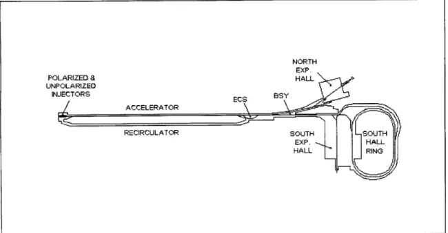
The Bates facility is a linac (linear accelerator) which uses either a thermionic or polarized electron gun to inject electrons into a sequence of RF accelerating stations. The beam delivery system consists of the linac, all beam lines, and the South Hall Ring, as shown in the Figure 1-1 below. Within this system, there are several subsystems,
including the Injector, Acceleration sections, and Recirculator to mention a few of these.
Each of these subsystems must be tuned sequentially in order to ensure the delivery of a stable beam to an experiment.
1.2 Accelerator Beam Control
Determining the proper settings for each of the subsystems listed above is a time consuming procedure.2 Therefore, the use of methods which expedite these processes are desired. One method, which has been proven to be an invaluable tool, is EPICS. EPICS (Experimental Physics and Industrial Control System) is a set of software tools and applications which was produced under a government contract. EPICS has many uses, including applications toward data acquisition and control systems.
The positioning of the electron beam in the linac currently involves many steps. To aid in this process, lutes are used to measure beam position and beam profile. Lutes are wire scanners, which consist of thin tungsten wires. They operate by scanning these wires across the beam.3 When the beam hits the wire, secondary electrons are ejected out which causes a secondary current to flow, thus allowing the measurement of the beam intensity on the wire as a function of the wire position.4 From the beam intensity read from the lutes, the beam position and beam profile can be determined.
1.2.1 Existing Protocol
Presently, after lutes are manually positioned, the "Linacprofile" program is run to determine and display beam position and profile. This program uses the lutes along the length of the linac to measure the beam centroid position and beam size along the length
of the linac. Horizontal and vertical data will then be displayed separately in graphical form on the workstation screen being used. There is also a "Lutes" program, which is used to set the parameters on the lutes along the linac. It is this tedious process of determining lute parameters and implementing them that EPICS will convert to an automatic system.
The automatic positioning of the electron beam provides an efficient way to situate the electron beam for minimum deviation from beam trajectory. The automatic
positioning system allows the operator to set the electron beam in a designated path using wire scanners, motors, and steering elements. The system makes use of an interactive screen, created using the EPICS tool MEDM, which is described in this document. The automatic positioning system also allows the operator to correct for any variations in beam trajectory and to change settings using MEDM. The experimental set up for the automatic positioning system and the graphical interface, along with testing procedures will be discussed in detail in the chapters that follow.
2.0 Experimental Topology and Analysis
2.1 Hardware ComponentsThe wire-scanners, or lutes, are positioned using a motor set up. The experimental motor set up consists of a motor control board, analog 1/0 boards, a timing board, a processor board, a LVDT, a signal generator, and a VMEbus system. These will be discussed in detail separately.
2.1.1 Motor Control Board
For the automatic positioning system, stepper motors will be employed to allow a variable step size for each scan. These motors are used in conjunction with the OMS Motor Control board (VME 8) designed by Oregon Microsystems. The OMS board has many features that are conducive to the proper operation of the automatic positioning system. It uses 'microstepping' techniques for increased position and resolution and decreased low speed resonance. The VME 8 also provides controlled acceleration to a predefined peak speed followed by a constant velocity and controlled deceleration to a
stop. This is done by calculating velocity 1,024 times each second, providing a very smooth acceleration curve. The VME 8 board can also command the motor to accelerate to a velocity and hold that velocity until told to stop or change to a new velocity. The VME 8 board option of a linear velocity ramp for ramping the motor to speed is used for the automatic positioning system and is governed by the following equations:
v =At (1)
V2
S A (2)
, where v is the velocity, Am is a constant acceleration, and s is the distance required to accelerate at the acceleration Am to peak velocity Vp. The VME 8 board also allows for a half-sinusoid acceleration ramp and a parabolic velocity ramp, both of which can be readily employed.
2.1.2 Analog I/O Board
For the experimental set up, an analog 1/0 board is used to collect data. The VMIVME-4514A (VMIC 4514A) board designed by VME Microsystems International Corporation was chosen for this purpose. It is a 16-channel, 12-bit analog input/output board with a built-in analog-to-digital converter and digital-to-analog converter. The VMIC 4514A provides 16 analog inputs and 16 analog outputs, both of which can be programmed to operate in a variety of voltage ranges. The VMIC 45114A is set for the 10V (bipolar) range for the experimental set up.
There are three analog-to-digital scanning modes for the VMIC 4514A. They are random polling, scanning polling, and auto scanning. Auto scanning is the default mode. In this mode, all 16 channels are continuously scanned, their inputs digitized, and their data stored in a dual port register. When all the inputs have been digitized, this process repeats itself starting with the first input. The digitized data is readily available at the VMEbus interface. In the experimental set up, the auto scanning mode is employed.
In the final set up, a different analog board is used for collecting data. This is the Caen board designed by the Costruzioni Apparecchiature Elettroniche Nucleari S.p.A company. It is similar to the VMIC 4514A board. The Caen board is a charge integrating Analog/Digital Conversion board with eight independent channels capable of converting
the charge associated with an input signal to a 16-bit word. There are on-board jumpers that need to be set accordingly to insure correct operation. Currently, jumper 1 (JP1) is set so that interrupts are generated when the FIFO is not empty and jumper 3 (JP3) is set so that the Caen board obtains an external trigger. These settings cause data to be accumulated as long as there is memory available on the Caen board and the board is ready to accept data.
2.1.3 Timing Board
A timing board is used in the final set up in conjunction with the Caen analog input board. The board of choice is the Argonne Timing board developed at Argonne National Laboratory. The Argonne board is a 2-channel VME digital delay generator. The two channels are independent and can be clocked either internally by a 40MHz
crystal or externally. There are 32 bits available for delay and width settings. Each channel also has a trigger input or can be triggered from the VMEbus.
2.1.4 Miscellaneous Hardware
There are also other pieces of hardware used of in the experimental set up. The processor is a Motorola MV167 board running at 33MIz. There are on board Abort and Reset buttons or the board can also be reset remotely. A LVDT (Linear Variable
Differential Transformer) is used in connection with the stepper motor. The LVDT produces an electrical output proportional to the position of its core. The stepper motor drives a metal plate back and forth, which in turn moves the LVDT back and forth. As the LVDT moves, the voltage corresponding to the current motor position is read back
through the VMIC 4514A board as an analog input and this data is made available to the VMEbus. This can be seen in Figure 2-1 below.
Motor Control Board
Motor LVDT
VMIC 4514A
Metal Plate
Figure 2-1 - LVDT/Motor Set up
A signal generator is used to trigger the Argonne board at 60Hz. The
corresponding delay and width settings are fixed such that the board is triggered with 60Hz pulses. All communication between 1/0 cards, timing cards, and motor control is done using the VMEbus system interface. A 21-slot chassis is used for the experimental set up to allow for easy insertion/removal of cards and also to permit quick access to backplane connectors for data retrieval. A diagram of this is shown in Figure 2-2 on the following page.
21-slot chassis
1ii11i1i111111
Motor and LVDT Connections Connections to VMEbus Inserted
Boards Power
Figure 2-2 - Experimental Set up Chassis
2.2 Hardware-Related Software Components
EPICS (Experimental Physics and Industrial Control System) is used to coordinate all motor control and data collection. EPICS is a set of software tools and
applications jointly developed by Argonne National Laboratory and Los Alamos National Laboratory for the purpose of controlling particle accelerators and large experiments.
EPICS provides operator interface to all control system parameters through interactive displays and alarm management through a table entry alarm file. Application developers can create a control system using the EPICS software components and tools. The basic
components are:
e OPI: Operator Interface. This is a UNIX based workstation which can run
" IOC: Input Output Controller. This is VME based chassis containing a
Motorola 68xxx processor, various I/O modules, and VME modules that provide access to other 1/0 buses.
" LAN: Local area network. This is the communication network, which allows the IOCs and OPIs to communicate.
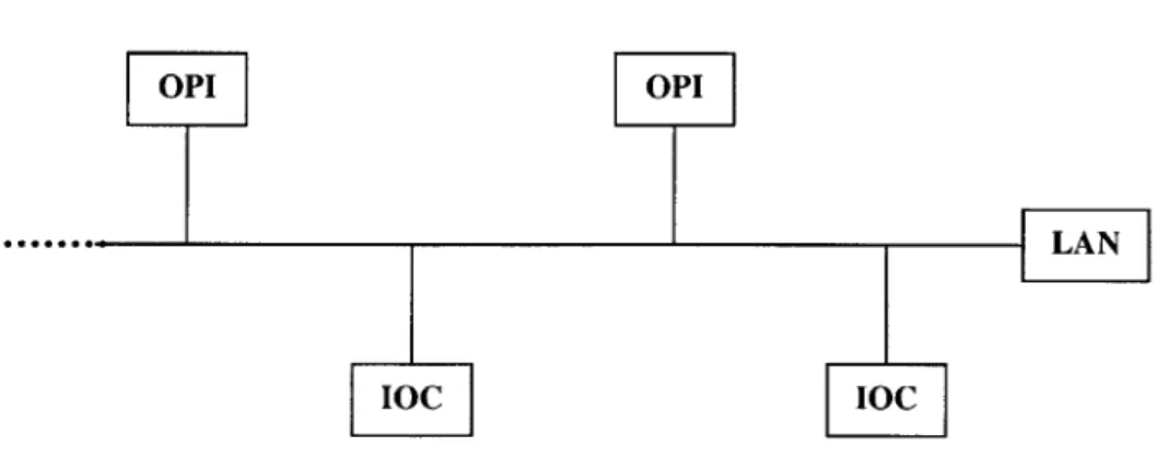
Figure 2-3 below shows the basic physical structure of a control system implemented through EPICS.
OPI OPI
LAN]
Figure 2-3 - Physical Structure of an EPICS Control System
EPICS provides a graphical tool for constructing systems dealing with input/output scanning, data conversions, and continuous control. It is called GDCT
(Graphical Database Configuration Tool). GDCT allows the user to build EPICS
databases and visualize links between records contained within these databases and their process variables. A process variable is the name of a field of a record in a database, usually but not necessarily an IOC database. The name is of the form record.field. EPICS
supports a large and extensible set of record types, for example, ai (Analog Input), ao (Analog Output), etc. Each record type has a fixed set of fields. Some fields are common
to all record types and others are specific to particular record types. Every record has a record name and every field has a field name. The first field of every database record holds the record name, which must be unique across all IOCs attached to the same
network.5 Each record type has an associated record support module and can have a set of device specific support modules. A few of these will be discussed in the incoming
sections.
In the experimental set up for the automatic positioning system, a database was created to test the functionality of the motor control board and also to confirm the
input/output relationship between the motor position and LVDT readings. The database is
called lute2_test.db and has a corresponding display file named lute2_test. This database
will be discussed in the next section. The code for lute2_test.db can be found in Appendix A. A display was created for the experimental set up for the automatic
positioning system using MEDM (Motif Editor and Display Manager), which will also be discussed later. In this section, the various records used in the experimental set up
database are described.
2.2.1 Motor Control Record
The GDCT motor control record type used in the lute2_test.db database was obtained from Argonne National Laboratory. This record is used to control motor position and velocity. The record maintains two coordinate systems for motor position ("user" and "dial" coordinates) and displays drive and readback values. The stepper motor used for the automatic positioning system can be controlled in either position mode or velocity mode from the motor control record. Position mode moves a device to a position
while velocity mode causes the motor to revolve continuously. The position mode option is suitable for the automatic positioning system requirement of moving wire scanners back and forth to specific locations.
The motor record has the standard fields for specifying circumstances under which the record will be processed. For the automatic positioning system, the motor record is scanned passively, meaning that its processing depends on the processing of other records to which it is linked. When scanned, it will compare the actual motor position to its desired motor position and attempt to achieve the desired position. The
setup parameter for the motor acceleration (ACCL) is specified as 0.2 seconds in the motor record. The time specified in ACCL determines the seconds the stepper motor will take to reach the specified velocity and also the number of seconds it will take to come to a stop at the new position. The units for position used in the motor record is millimeters, specified in the EGU field. The velocity used when the motor is commanded to move to a new position is specified in the VELO field as 5 millimeters/second for the automatic positioning system. The current position of the motor is held in the VAL field of the motor record. By changing the contents of the VAL field, the stepper motor is forced to move to the new position specified by the new value in the VAL field. VAL must fall within the upper dial limit (DHLM) and the lower dial limit (DLLM) in order for the stepper motor to commence any movement. These values are 111.3554 mm for DHLM and -111.3554 mm for DLLM.
2.2.2 Analog Input Record
The GDCT ai (analog input) record type is used in the experimental set up
lute2_test.db database. This record type is used normally to obtain an analog value from
hardware and then convert it to engineering units. For the automatic positioning system, this record type is used in coordination with the Caen board and the VMIC 4514A board. The record supports conversion to engineering units and graphics and control limits. Values are read from the Analog 1/0 board into the RVAL field. These values are then converted just like raw values obtained from hardware device support modules. The conversion is done by selecting the LINEAR option within the record and by providing the record with upper and lower voltage limits for the expected values. The ai record then uses these parameters to calculate a final value, which it places in the VAL field of the record, thus making it available for output or further calculations. For the ai record using the VMIC 4514A as its device type, the voltage limits are +5V, since these are also the voltage limits of the LVDT where the VMIC 4514A retrieves its values. The voltage limits for the Caen board are +10V unipolar. There are many other ai records within the
lute2_test.db file. These ai records however do not have any specific device support and
are present in the database to hold values obtained from other sources.
2.2.3 Timing Board Record
The timing board record is used in conjunction with the ai record type associated with the Caen board. It is associated with the Argonne Timing board. The timing board record is used to set the integrating time. The rate at which the Caen board collects data is set by the electron gun via the Argonne board. This is accomplished by setting the pulse
delay (DLY) and pulse width (WIDE) fields within the timing record so that the Caen board operates as desired. These fields determine the characteristics of the pulse that is generated by the record. The pulse delay (DLY) field is the most important of these fields. In it, the time delay is specified, from the trigger edge until the generation of the pulse. In the time units (UNIT) field, the units of time for the delay is specified. The UNIT for the automatic positioning system is Nanoseconds. The DLY for the automatic positioning system is measured during the final set up stage. The time duration of the pulse is specified in the pulse width (WIDE) field, which also uses the UNIT field for its time units. The WIDE for the automatic positioning system is 600 Nanoseconds. In the record, an external trigger source is specified as a signal generator that is used to trigger the timing board as discussed earlier.
2.2.4 Calcout (Wait) Record
The GDCT Calcout (Calculation Output) record type is used extensively in the experimental set up lute2_test.db database. The Calcout record has 12 input links, which can be used to calculate a final value. This final value is placed in the VAL field of the Calcout record after being computed from the string entered in the CALC field, which uses the 12 inputs to calculate VAL.
There are many applications for the Calcout record type. One of these
applications, which is employed in lute2_test.db, is the use of the Calcout record to wait for certain events to occur. By specifying when the output should be executed, the Calcout record can delay the processing of other records it is linked to or wait for the
input to reach a certain state before initiating a response. The Calcout record is therefore a useful aid for regulating data flow.
2.2.5 Scanning Record
In order to coordinate the processing of the records in the lute2_test.db database, the GDCT Scan record is utilized. The basic function of a scan record is to move
"positioners" through a series of steps and record "detector" data at each of the positions (the whole sequence is referred to as a "scan"). Once the scan parameters are properly initialized, the scan record coordinates the entire scan and sends notification when the scan is complete. The data is stored in arrays within the record, which allows for much faster scans. A single scan record supports a one-dimensional scan but it is also possible to link scan records together to define multi-dimensional scans.
The scan record type has no associated device specific support modules like the motor control board record and the timing record. In the experimental set up, the
"positioner" is the stepper motor and the "detector" is the LVDT in conjunction with the VMIC 4514A board. In the lute2_test.db database, the scan record is linked to the motor control board record and the VMIC 4514A ai record. The scan record contains the parameters needed by the stepper motor record, which is necessary for motor movement. These fields include the following:
1. PlPV: Process variable name of the first positioner record (or stepper motor record for the experimental set up).
2. PlSP: Starting position for the first positioner. 3. PlEP: Ending position for the first positioner.
4. PI: Step increment for first positioner.
5. MPTS: Maximum number of data points to be collected during scan (used to allocate memory).
6. NPTS: Number of data points to collect during scan (constrained to be
less than or equal to MPTS).
Once the fields PlSP, PISI, and NPTS are the defined, a scan can execute. While PlSP,
PISI, and PlEP are not constant parameters and can be changed, MPTS and NPTS have
both been specified as 100 in the experimental set up.
The scan record also has the fields needed by LVDT and VMIC 4514A for collecting data. These fields are:
1. D1PV: Process variable name of first detector record (VMIC 4514A ai
record for experimental set up).
2. T1PV: Process variable name for the "detector trigger" written to between the positioning phase and data acquisition phase of scan.
(Same as D1PV for experimental set up).
In order to begin the scan, a "1" is written to the Execute Scan field (EXSC) of the scan record. The record automatically resets this field to "0" when the scan is complete. When a scan is initiated, the positioner is moved into its starting position (PlSP). When the scan record is notified that this step has completed, it then triggers the detector (T1PV) to begin collecting data as the positioner moves from its starting positioning to its ending position (P1EP). When the scan has completed, the data collected during the scan is available in the following scan record array fields:
1. PIRA: First positioner readback array (contains motor position at each point during the scan).
2. DIDA: First detector data array (contains detector data for each position in the scan).
The data can be passed on to other records for further manipulation or displayed using simple x-y plot techniques. The scan record can be instructed to begin another scan or, through proper choice of start and end positions, send the motor to a specified position without scanning.
2.2.6 Other Record Types
The GDCT dfanout record type is used in the experimental set up lute2_test.db database. The dfanout record is used to forward data to up to eight other records. It has no associated device support. In the lute2_test.db database, it is used to trigger the
processing of other records.6
2.3 Experimental Set-up User Interface
EPICS also provides another tool called MEDM (Motif Editor and Display Manager). MEDM is an EPICS extension in that it has been designed to work intimately with EPICS. It is a graphical user interface used to design and implement control screens, called displays, that consist of a collection of graphical objects that display and/or change the values of EPICS process variables. The objects available include buttons, meters,
sliders, text displays/entries, and graphs. It has two modes of operation, EDIT and EXECUTE. Displays are created and edited in EDIT mode, and they are run in
EXECUTE mode. A graphical interface was made for the experimental topology, named
lute2_display.adl. The components of this graphical interface include:
e Start Position, End Position, and Step Increment Text Entry Objects
e START Button, STOP Button, and RESET Button
e PAUSE Button and RESUME Button e Scan Data X-Y Plot
In the following sections, these various elements, contained in lute2_display.adl, are discussed.
2.3.1 Start Position, End Position, and Step Increment Text Entry Objects The start position, end position, and step increment fields of the scan record are variable and are entered by the operator. In order to allow for this interaction, the MEDM Text Entry tool is employed. The Text Entry has Object (X Position, Y Position, Width, Height), Control (Control Channel, Foreground, Background), Limits (Precision), Format, and Color Mode attributes. The Text Entry provides an entry box to display the value of a process variable, where it can be edited and changed. The value is not changed until the Return key is pressed. In lute2_display.adl, the start position, end position, and step increment parameters needed by the scan record are implemented with text entry boxes. They are named "Min", "Max", and "Step" in lute2.display.adl, respectively. Each of these text entry boxes is linked to a Calcout record in the lute2_test.db database. The Calcout records hold the values entered by the operator and make these values available to any record in the database. Once the operator enters a value into each of these boxes, a scan can be initiated.
2.3.2 START Button, STOP Button, and RESET Button
In order to initiate a scan, a "1" must be written to the scan record EXSC field, as discussed earlier. To accomplish this task, a START button was created in the
lute2display.adl graphical interface using the MEDM Message Button tool. The
Message Button has Object (X Position, Y Position, Width, Height), Control (Control Channel, Foreground, Background), and Color Mode attributes. In addition, there are a Message Label, a Press Message, and a Release Message. The Message Label is the label
on the Message Button, ("START" in lute2_display.adl). When the Message button is pressed or released, the process variable is set to the Press Message or Release Message, respectively. These values are commensurate with the type of the process variable. For the START button, the Press Message is a "1", and the Release Message is a "0". The control channel or process variable is a dfanout record in the lute2_test.db database. When the dfanout record is set to a "1"', it triggers the processing of three consecutive Calcout records which contain the values of the Start position, End position, and Step
increment which were entered by the operator and are also needed by the scan record for processing. After these are processed, a fourth Calcout record is used to initiate the scan record by sending a "1" to the scan record EXSC field. The scan record then processes as described in Section 2.2.5.
The STOP button was created in a similar technique using the MEDM Message Button tool. The Message Label on the Message Button, is "STOP" in lute2_display.adl. The Press Message is a "1" and the Release Message is a "0" for the STOP button, The control channel is also dfanout record in the lute2_test.db database. When the dfanout record is set to a "1,, it triggers the processing of two consecutive Calcout records which
contain constant values for the home position of the stepper motor. In the experimental set up, these values are both "0.0". After these are processed, a third Calcout record is used to initiate the scan record by sending a "1" to the scan record EXSC field. The scan record then processes, bringing the stepper motor back to its home position and another scan can initiate.
The RESET button was also created in a similar technique using the MEDM Message Button tool. The Message Label on the Message Button, is "RESET" in
lute2display.adl. The Press Message is a "1" and the Release Message is a "0" for the
RESET button, The control channel is also dfanout record in the lute2_test.db database. When the dfanout record is set to a "1", it triggers the processing of two consecutive Calcout records which contain constant values for a position beyond that of the stepper motor home position. In the experimental set up, these values are both "-0.2". The RESET button is used when there is a power failure or and when an IOC rebooted. It
ensures the operator that the stepper motor position is really at the beginning of its path and not in an unknown position. This prevents the operator having to physically check and measure the location of the stepper motor. After these are processed, a third Calcout record is used to initiate the scan record using the same technique as the START and STOP buttons. The scan record then processes, bringing the stepper motor back to its home position and another scan can initiate.
2.3.3 PAUSE Button and RESUME Button
The PAUSE button and the RESUME button were also created using the MEDM Message Button tool. The Message Labels on the buttons are "PAUSE" and "RESUME"
respectively, in lute2_display.adl. The Press Message is a "0" and the Release Message is a "1" for the PAUSE button. The control channel for the PAUSE button is the stepper motor record SPMG field in the lute2_test.db database. When the stepper motor record SPMG field is set to "1", it triggers the stepper motor record to stop in its current position, thus implementing the PAUSE feature. The Press Message for the RESUME button is a "3" and the Release Message is a "3". The control channel for the RESUME button is also the stepper motor record SPMG field in the lute2_test.db database. When the stepper motor record SPMG field is set to "3", it triggers the stepper motor record to resume movement from its current position to the previously entered end position, thus implementing the RESUME feature.
2.3.4 Scan Data X-Y Plot
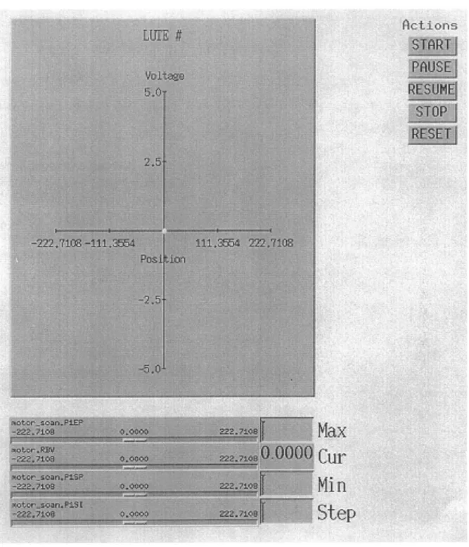
Using the MEDM Cartesian Plot tool, an X-Y plot was created to display the relationship between the voltage read back through the VMIC 4514A card and stepper motor position. The Cartesian Plot has Object (X Position, Y Position, Width, Height) attributes, Plot (Title, X Label, Y Label, Foreground, Background) attributes, Trigger Channel, and X/Y/Trace Data that can be specified.7 In lute2_display.adl, the Plot title is
"LUTE", the X Label is "Position", and the Y label is "Voltage". The X Trace Data is specified as the scan record PIRA fields which contains the array of motor positions visited. The Y Trace Data is specified as the scan record DiDA field, which contains the array of detector data recorded at each motor position in the PIRA array. The Trigger Channel is a process variable that causes the entire plot to be updated. The plot is updated whenever the value of that process variable changes. The Trigger Channel for
lute2jisplay.adl is the EXSC field of the scan record. Therefore, the X-Y Plot is updated
when a scan is executed. A sample screen shot of the X-Y plot and the other elements contained in lute2_display.adl is shown in Figure 2-4.
Actions~
Ste
- -t , X
tte
2.4 Analysis of Experimental Set-up
The experimental set up was tested and analyzed using a Sun workstation as the OPI. Channel access is used for all communication between the OPI and the IOC across the LAN. Channel access allows the operator to easily access and modify process variables at run-time. Once the lute2_test.db database has been loaded into the IOC, the
lute2display.adl user interface can be put in EXECUTE mode. In EXECUTE mode, the
user may now enter values for the various process variables needed to begin a scan. In Figure 2-5, a sample scan result is displayed. The following values were entered for the scan parameters:
e MAX = 215.40 mm
e MIN = 176.20 mm
e STEP = 0.01 mm
After these values were specified, the scan was initiated by clicking on the START button, with the data shown in Figure 2-5. The linear relationship between the LVDT voltage reading and the motor position is as expected. As the motor moves the plate shown in Figure 2-1 towards the MAX position, the LVDT voltage reading increases linearly with position. This result also verifies the correct operation of the "Linear Mode" in the stepper motor record. Therefore, the final topology can be incorporated into the current electron beam positioning system and verified for correct operation in
3.0 Final Topology and Analysis
3.1 Hardware Components
The hardware components used in the final topology are the Argonne timing board, the Caen analog/digital conversion board, the OMS motor control board, and the MVME-167 processor board. All other needed components, such as an external trigger for the timing board, are provided through present beamline instrumentation. A test chassis is positioned along the beamline for all of the above hardware. A connection is made between the motor board and a lute along the accelerator path to provide motion control over the lute. These components are controlled from an OPI using the EPICS tools discussed in the next section.
3.2 Software Components
The software components used for the final topology are the same as those used for the experimental set up with minor modifications. The lute2_test.db database is changed to accommodate the use of the Caen board in connection with the Argonne Timing board. This is accomplished by simply adding the Timing record discussed in Section 2.1.3 to
the lute2_test.db database and exchanging the VMIC 4514A board ai record with that of
a Caen board ai record. The new database is named lute2.db and is loaded onto the IOC that contains the hardware listed in the previous section. The lute2_display.adl user interface is also used to define all parameters needed for scan initiation and to control
3.3 Analysis of Final Topology
The final set up was tested and analyzed using the same techniques as the
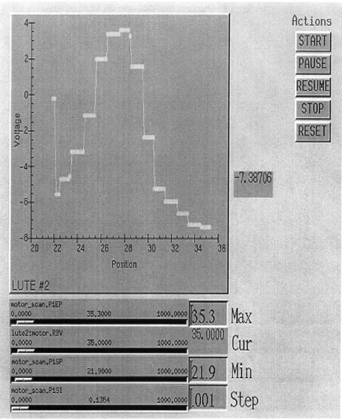
experimental set up, i.e. channel access. In EXECUTE mode of the lute2_display.adl user interface, the following values were entered for the scan parameters:
e MAX = 35.3 mm
e MIN= 21.9 mm
* STEP = 0.001 mm
After these values were specified, the scan was initiated by clicking on the START button, with the data shown in Figure 3-1. The expected Gaussian relationship between the beam voltage reading and the motor position can also be seen in Figure 3-1. The plot in Figure 3-1 shows that as the lute passes through the beam, the maximum beam
intensity occurs at the center and drops off as the lute moves away from the beam center. This result confirms the correct performance of the lute2.db database in the final set up. Therefore, after minor modifications to the existing set up, the final topology can be incorporated into the electron beam positioning system.
4.0 Discussion and Future Work
4.1 Discussion
The automatic positioning system for the electron beam at the Bates Linear Accelerator expedites beam trajectory corrections. Using the lute2.db database and the
lute2_display.adl user interface, it can be determined where the electron beam is
currently positioned along the accelerator path through control of wire scanners and motors. It can also be ascertained the amount that the electron beam should be
repositioned for minimum beam trajectory deviation. The beam can then be repositioned using steering elements along the beam path to correct for any deviation.
4.2 Future Work
The automatic positioning system is created using the EPICS tools GDCT and MEDM. This allows for easy modification of the database and/or the user interface, as future needs arise. Future modifications to the automatic positioning system include:
" Reconfiguring the lute2.db database such that scans are continuous (i.e. scans continuously back and forth between Start position and End position until stopped by operator)
" Modifying the lute2_display.adl user interface to accommodate two lute profiles at the same time instead of one profile
" Closed-loop positioning using lutes, beam position monitors , and steering coils
Appendix
-lute2_test.db Database Code
grecord(ai,"ywidth") { field(DESC,"") field(ASG,"") field(SCAN,"Passive") field(PINI,"NO") field(PHAS,"O") field(EVNT,"O") field(TSEL,"") field(DTYP,"Soft Channel") field(DISV," 1") field(SDIS,"") field(DISS,"NOALARM") field(PRIO,"LOW") field(FLNK,"O") field(INP,"") field(PREC,"O") field(LINR,"NO CONVERSION") field(EGUF,"O") field(EGUL,"O") field(EGU,"") field(HOPR,"O") field(LOPR,"O") field(AOFF,"O") field(ASLO," 1") field(SMOO,"O") field(HIHI,"O") field(LOLO,"O") field(HIGH,"O") field(LOW,"O") field(HHSV,"NOALARM") field(LLSV,"NOALARM") field(HSV,"NOALARM") field(LSV,"NOALARM") field(HYST,"O") field(ADEL,"O") field(MDEL,"O") field(SIOL,"") field(SIML,"") field(SIMS,"NOALARM")}
grecord(ai,"y-peak") field(DESC,"") field(ASG,"") field(SCAN,"Passive") field(PINI,"NO") field(PHAS,"O") field(EVNT,"0") field(DTYP,"Soft Channel") field(DISV," 1") field(SDIS,"") field(DISS,"NOALARM") field(PRIO,"LOW") field(FLNK,"O") field(INP,"") field(PREC,"O") field(LINR,"NO CONVERSION") field(EGUF,"O") field(EGUL,"O") field(EGU,"") field(HOPR,"O") field(LOPR,"O") field(AOFF,"O") field(ASLO," 1") field(SMOO,"O") field(HIHI,"O") field(LOLO,"0") field(HIGH,"O") field(LOW,"O") field(HHSV,"NOALARM") field(LLSV,"NOALARM") field(HSV,"NOALARM") field(LSV,"NOALARM") field(HYST,"O") field(ADEL,"O") field(MDEL,"O") field(SIOL,"") field(SIML,"") field(SIMS,"NOALARM")}
grecord(ai,"y-center") { field(DESC,"") field(ASG,"") field(SCAN,"Passive") field(PINI,"NO") field(PHAS,"O") field(EVNT,"O") field(TSEL,"") field(DTYP,"Soft Channel") field(DISV,"1") field(SDIS,"") field(DISS,"NOALARM") field(PRIO,"LOW") field(FLNK,"0") field(INP,"")field(LINR,"NO CONVERSI field(EGUF,"O") field(EGUL,"O") field(EGU,"") field(HOPR,"O") field(LOPR,"O") field(AOFF,"O") field(ASLO," 1") field(SMOO,"O") field(HIHI,"O") field(LOLO,"O") field(HIGH,"O") field(LOW,"O") field(HHSV,"NOALARM") field(LLSV,"NOALARM") field(HSV,"NOALARM") field(LSV,"NOALARM") field(HYST,"O") field(ADEL,"O") field(MDEL,"O") field(SIOL,"") field(SIML,"") field(SIMS,"NOALARM") grecord(ai,"x-width") field(DESC,"") field(ASG,"") field(SCAN,"Passive") field(PINI,"NO") field(PHAS,"O") field(EVNT,"O") field(TSEL,"") field(DTYP,"Soft Channel") field(DISV," 1") field(SDIS,"") field(DISS,"NOALARM") field(PRIO,"LOW") field(FLNK,"O") field(INP,"") field(PREC,"O") field(LINR,"NO CONVERSI field(EGUF,"O") field(EGUL,"O") field(EGU,"") field(HOPR,"O") field(LOPR,"O") field(AOFF,"O") field(ASLO," 1") field(SMOO,"O") field(HIHI,"O") field(LOLO,"O") ON") field(HIGH,"O") field(LOW,"O") field(HHSV,"NOALARM") field(LLSV,"NOALARM") field(HSV,"NOALARM") field(LSV,"NOALARM") field(HYST,"O") field(ADEL,"O") field(MDEL,"O") field(SIOL,"") field(SIML,"") field(SIMS,"NOALARM") } grecord(ai,"x-peak") field(DESC,"") field(ASG,"") field(SCAN,"Passive") field(PINI,"NO") field(PHAS,"O") field(EVNT,"O") field(TSEL,"") field(DTYP,"Soft Channel") field(DISV,"1") field(SDIS,"") field(DISS,"NOALARM") field(PRIO,"LOW") field(FLNK,"O") field(INP,"") field(PREC,"O") field(LINR,"NO CONVERSION") field(EGUF,"O") field(EGUL,"O") field(EGU,"") field(HOPR,"O") field(LOPR,"O") field(AOFF,"O") field(ASLO," 1") field(SMOO,"O") field(HIHI,"O") field(LOLO,"O") field(HIGH,"O") field(LOW,"O") field(HHSV,"NOALARM") field(LLSV,"NOALARM") field(HSV,"NOALARM") field(LSV,"NOALARM") field(HYST,"O") field(ADEL,"O") field(MDEL,"O") field(SIOL,"") field(SIML,"") ON")
field(SIMS,"NOALARM")
}
grecord(ai,"xcenter") field(DESC,"") field(ASG,"") field(SCAN,"Passive") field(PINI,"NO") field(PHAS,"O") field(EVNT,"O") field(TSEL,"") field(DTYP,"Soft Channel") field(DISV," 1") field(SDIS,"") field(DISS,"NOALARM") field(PRIO,"LOW") field(FLNK,"O") field(INP,"") field(PREC,"O") field(LINR,"NO CONVERSION") field(EGUF,"O") field(EGUL,"O") field(EGU,"") field(HOPR,"O") field(LOPR,"O") field(AOFF,"O") field(ASLO," 1") field(SMOO,"O") field(HIHI,"O") field(LOLO,"O") field(HIGH,"O") field(LOW,"O") field(HHSV,"NOALARM") field(LLSV,"NOALARM") field(HSV,"NOALARM") field(LSV,"NOALARM") field(HYST,"O") field(ADEL,"O") field(MDEL,"O") field(SIOL,"") field(SIML,"") field(SIMS,"NOALARM")}
grecord(ai,"aperture-low") { field(DESC,"") field(ASG,"") field(SCAN,"Passive") field(PINI,"NO") field(PHAS,"O") field(EVNT,"O") field(DISV," 1") field(SDIS,"") field(DISS,"NOALARM") field(PRIO,"LOW") field(FLNK,"O") field(INP,"") field(PREC,"O") field(LINR,"NO CONVERSION") field(EGUF,"O") field(EGUL,"O") field(EGU,"") field(HOPR,"O") field(LOPR,"O") field(AOFF,"O") field(ASLO," 1") field(SMOO,"O") field(HIHI,"O") field(LOLO,"O") field(HIGH,"O") field(LOW,"O") field(HHSV,"NOALARM") field(LLSV,"NOALARM") field(HSV,"NOALARM") field(LSV,"NO ALARM") field(HYST,"O") field(ADEL,"O") field(MDEL,"O") field(SIOL,"") field(SIML,"") field(SIMS,"NOALARM")}
grecord(ai,"aperture-high") { field(DESC,"") field(ASG,"") field(SCAN,"Passive") field(PINI,"NO") field(PHAS,"O") field(EVNT,"O") field(TSEL,"") field(DTYP,"Soft Channel") field(DISV," 1") field(SDIS,"") field(DISS,"NOALARM") field(PRIO,"LOW") field(FLNK,"O") field(INP,"") field(PREC,"O") field(LINR,"NO CONVERSION") field(EGUF,"O")field(HOPR,"O") field(LOPR,"O") field(AOFF,"O") field(ASLO," 1") field(SMOO,"O") field(HIHI,"O") field(LOLO,"O") field(HIGH,"O") field(LOW,"O") field(HHSV,"NOALARM") field(LLSV,"NOALARM") field(HSV,"NOALARM") field(LSV,"NOALARM") field(HYST,"O") field(ADEL,"O") field(MDEL,"O") field(SIOL,"") field(SIML,"") field(SIMS,"NOALARM") grecord(ai,"aperture center") { field(DESC,"") field(ASG,"") field(SCAN,"Passive") field(PINI,"NO") field(PHAS,"O") field(EVNT,"O") field(TSEL,"") field(DTYP,"Soft Channel") field(DISV,"1") field(SDIS,"") field(DISS,"NOALARM") field(PRIO,"LOW") field(FLNK,"O") field(INP,"") field(PREC,"O") field(LINR,"NO CONVERSION")' field(EGUF,"O") field(EGUL,"O") field(EGU,"") field(HOPR,"O") field(LOPR,"O") field(AOFF,"O") field(ASLO," 1") field(SMOO,"O") field(HIHI,"O") field(LOLO,"O") field(HIGH,"O") field(LOW,"O") field(HHSV,"NO_ALARM") field(LLSV,"NOALARM") field(HSV,"NOALARM") field(LSV,"NOALARM") field(HYST,"O") field(ADEL,"O") field(MDEL,"O") field(SIOL,"") field(SIML,"") field(SIMS,"NOALARM")
}
grecord(ai,"Mvmic") field(DESC,"Analog Input") field(ASG,"") field(SCAN,"Passive") field(PINI,"NO") field(PHAS,"O") field(EVNT,"O") field(TSEL,"") field(DTYP,"Vmic 4514") field(DISV," 1") field(SDIS,"") field(DISS,"NO ALARM") field(PRIO,"LOW") field(FLNK,"Wait_2.VAL") field(INP,"#CO SO @") field(PREC,"5") field(LINR,"LINEAR") field(EGUF," 10") field(EGUL,"-10") field(EGU,"volts") field(HOPR,"10") field(LOPR,"-10") field(AOFF,"O") field(ASLO," 1") field(SMOO,"O") field(HIHI,"O") field(LOLO,"O") field(HIGH,"O") field(LOW,"O") field(HHSV,"NOALARM") field(LLSV,"NOALARM") field(HSV,"NOALARM") field(LSV,"NOALARM") field(HYST,"O") field(ADEL,"O") field(MDEL,"O") field(SIOL,"") field(SIML,"") field(SIMS,"NOALARM")}
grecord(calcout,"Wait_1") { field(DESC,"")field(ASG,"") field(SCAN,"Passive") field(PINI,"NO") field(PHAS,"O") field(EVNT,"O") field(TSEL,"") field(DISV," 1") field(SDIS,"") field(DISS,"NOALARM") field(PRIO,"LOW") field(FLNK,"O") field(CALC,"A") field(INPA,"motor.VAL PP MS") field(INPB,"") field(INPC,"") field(INPD,"") field(INPE,"") field(INPF,"") field(INPG,"") field(INPH,"") field(INPI,"") field(INPJ,"") field(INPK,"") field(INPL,"") field(OUT,"motorscan.EXSC PP MS") field(OOPT,"Every Time") field(ODLY,"O") field(DOPT,"Use OCAL") field(OCAL," I ") field(OEVT,"O") field(IVOA,"Continue normally") field(IVOV,"O") field(EGU,"") field(PREC,"5") field(HOPR,"O") field(LOPR,"O") field(HIHI,"O") field(LOLO,"O") field(HIGH,"O") field(LOW,"O") field(HHSV,"NOALARM") field(LLSV,"NOALARM") field(HSV,"NOALARM") field(LSV,"NOALARM") field(HYST,"O") field(ADEL,"O") field(MDEL,"O")
}
field(ASG,"") field(SCAN,"Passive") field(PINI,"NO") field(PHAS,"O") field(EVNT,"O") field(TSEL,"") field(DISV," 1") field(SDIS,"") field(DISS,"NOALARM") field(PRIO,"LOW") field(FLNK,"O") field(CALC,"A") field(INPA,"Mvmic.VAL PP MS") field(INPB,"") field(INPC,"") field(INPD,"") field(INPE,"") field(INPF,"") field(INPG,"") field(INPH,"") field(INPI,"") field(INPJ,"") field(INPK,"") field(INPL,"") field(OUT,"motorscan.EXSC PP MS") field(OOPT,"Every Time") field(ODLY,"O") field(DOPT,"Use OCAL") field(OCAL," 1") field(OEVT,"O") field(IVOA,"Continue normally") field(IVOV,"O") field(EGU,"") field(PREC,"5") field(HOPR,"O") field(LOPR,"O") field(HIHI,"O") field(LOLO,"O") field(HIGH,"O") field(LOW,"O") field(HHSV,"NO ALARM") field(LLSV,"NO ALARM") field(HSV,"NO ALARM") field(LSV,"NO ALARM") field(HYST,"O") field(ADEL,"O") field(MDEL,"O")}
field(ASG,"") field(SCAN,"Passive") field(PINI,"NO") field(PHAS,"O") field(EVNT,"O") field(TSEL,"") field(DISV," 1") field(SDIS,"") field(DISS,"NOALARM") field(PRIO,"LOW") field(FLNK,"O") field(CALC,"A") field(INPA,"1") field(INPB,"") field(INPC,"") field(INPD,"") field(INPE,"") field(INPF,"") field(INPG,"") field(INPH,"") field(INPI,"") field(INPJ,"") field(INPK,"") field(INPL,"") field(OUT,"motorscan.EXSC PP MS") field(OOPT,"Every Time") field(ODLY,"O") field(DOPT,"Use OCAL") field(OCAL," 1") field(OEVT,"O") field(IVOA,"Continue normally") field(IVOV,"O") field(EGU,"") field(PREC,"5") field(HOPR,"O") field(LOPR,"O") field(HIHI,"O") field(LOLO,"O") field(HIGH,"O") field(LOW,"O") field(HHSV,"NOALARM") field(LLSV,"NOALARM") field(HSV,"NOALARM") field(LSV,"NOALARM") field(HYST,"O") field(ADEL,"O") field(MDEL,"O")
}
grecord(calcout,"StopSP") field(DESC,"") MS") field(ASG,"") field(SCAN,"Passive") field(PINI,"NO") field(PHAS,"O") field(EVNT,"O") field(TSEL,"") field(DISV," 1") field(SDIS,"") field(DISS,"NO ALARM") field(PRIO,"LOW") field(FLNK,"StopEP.VAL") field(CALC,"") field(INPA," 1") field(INPB,"") field(INPC,"") field(INPD,"") field(INPE,"") field(INPF,"") field(INPG,"") field(INPH,"") field(INPI,"") field(INPJ,"") field(INPK,"") field(INPL,"") field(OUT,"motor-scan.PlSP PP field(OOPT,"Every Time") field(ODLY,"O") field(DOPT,"Use OCAL") field(OCAL,"O") field(OEVT,"O") field(IVOA,"Continue normally") field(IVOV,"O") field(EGU,"") field(PREC,"5") field(HOPR,"O") field(LOPR,"O") field(HIHI,"O") field(LOLO,"O") field(HIGH,"O") field(LOW,"O") field(HHSV,"NO ALARM") field(LLSV,"NO ALARM") field(HSV,"NOALARM") field(LSV,"NOALARM") field(HYST,"O") field(ADEL,"O") field(MDEL,"O")}
grecord(calcout,"StopEP") field(DESC,"")field(ASG,"") field(SCAN,"Passive") field(PINI,"NO") field(PHAS,"O") field(EVNT,"O") field(TSEL,"") field(DISV," 1") field(SDIS,"") field(DISS,"NOALARM") field(PRIO,"LOW") field(FLNK,"Stopscan.VAL") field(CALC,"") field(INPA," 1 ") field(INPB,"") field(INPC,"") field(INPD,"") field(INPE,"") field(INPF,"") field(INPG,"") field(INPH,"") field(INPI,"") field(INPJ,"") field(INPK,"") field(INPL,"") field(OUT,"motorscan.PlEP PP MS") field(OOPT,"Every Time") field(ODLY,"O") field(DOPT,"Use OCAL") field(OCAL,"O") field(OEVT,"O") field(IVOA,"Continue normally") field(IVOV,"O") field(EGU,"") field(PREC,"5") field(HOPR,"O") field(LOPR,"O") field(HIHI,"O") field(LOLO,"O") field(HIGH,"O") field(LOW,"O") field(HHSV,"NOALARM") field(LLSV,"NOALARM") field(HSV,"NOALARM") field(LSV,"NO ALARM") field(HYST,"O") field(ADEL,"O") field(MDEL,"O")
}
field(ASG,"") field(SCAN,"Passive") field(PINI,"NO") field(PHAS,"O") field(EVNT,"O") field(TSEL,"") field(DISV," 1") field(SDIS,"") field(DISS,"NO ALARM") field(PRIO,"LOW") field(FLNK,"O") field(CALC,"A-1.2") field(INPA," 1") field(INPB,"") field(INPC,"") field(INPD,"") field(INPE,"") field(INPF,"") field(INPG,"") field(INPH,"") field(INPI,"") field(INPJ,"") field(INPK,"") field(INPL,"") field(OUT,"") field(OOPT,"Every Time") field(ODLY,"O") field(DOPT,"Use OCAL") field(OCAL,"") field(OEVT,"O") field(IVOA,"Continue normally") field(IVOV,"O") field(EGU,"") field(PREC,"5") field(HOPR,"O") field(LOPR,"O") field(HIHI,"O") field(LOLO,"O") field(HIGH,"O") field(LOW,"O") field(HHSV,"NOALARM") field(LLSV,"NO ALARM") field(HSV,"NO ALARM") field(LSV,"NO ALARM") field(HYST,"O") field(ADEL,"O") field(MDEL,"O")}
grecord(calcout,"Start scan") {field(SCAN,"Passive") field(PINI,"NO") field(PHAS,"O") field(EVNT,"O") field(TSEL,"") field(DISV,"1") field(SDIS,"") field(DISS,"NOALARM") field(PRIO,"LOW") field(FLNK,"O") field(CALC,"A") field(INPA," 1 ") field(INPB,"") field(INPC,"") field(INPD,"") field(INPE,"") field(INPF,"") field(INPG,"") field(INPH,"") field(INPI,"") field(INPJ,"") field(INPK,"") field(INPL,"") field(OUTJ,"motorscan.EXSC PP MS") field(OOPT,"Every Time") field(ODLY,"O") field(DOPT,"Use OCAL") field(OCAL," 1 ") field(OEVT,"O") field(IVOA,"Continue normally") field(IVOV,"O") field(EGU,"") field(PREC,"5") field(HOPR,"O") field(LOPR,"O") field(HIHI,"O") field(LOLO,"O") field(HIGH,"O") field(LOW,"O") field(HHSV,"NOALARM") field(LLSV,"NOALARM") field(HSV,"NOALARM") field(LSV,"NOALARM") field(HYST,"O") field(ADEL,"O") field(MDEL,"O")
}
grecord(calcout,"StartStep") { field(DESC,"") field(ASG,"") field(SCAN,"Passive") field(PINI,"NO") field(PHAS,"O") field(EVNT,"O") field(TSEL,"") field(DISV," 1") field(SDIS,"") field(DISS,"NO ALARM") field(PRIO,"LOW") field(FLNK,"Startscan.VAL") field(CALC,"A") field(INPA,"Step-default.OCAL NPP NMS") field(INPB,"") field(INPC,"") field(INPD,"") field(INPE,"") field(INPF,"") field(INPG,"") field(INPH,"") field(INPI,"") field(INPJ,"") field(INPK,"") field(INPL,"") field(OUT,"motor-scan.PlSI PP MS") field(OOPT,"Every Time") field(ODLY,"O") field(DOPT,"Use CALC") field(OCAL," 1") field(OEVT,"O") field(IVOA,"Continue normally") field(IVOV,"O") field(EGU,"") field(PREC,"5") field(HOPR,"O") field(LOPR,"O") field(HIHI,"O") field(LOLO,"O") field(HIGH,"O") field(LOW,"O") field(HHSV,"NO ALARM") field(LLSV,"NO ALARM") field(HSV,"NO ALARM") field(LSV,"NOALARM") field(HYST,"O") field(ADEL,"O") field(MDEL,"O")}
grecord(calcout,"StartSP") field(DESC,"")field(ASG,"") field(SCAN,"Passive") field(PINI,"NO") field(PHAS,"O") field(EVNT,"O") field(TSEL,"") field(DISV," 1") field(SDIS,"") field(DISS,"NOALARM") field(PRIO,"LOW") field(FLNK,"StartEP.VAL") field(CALC,"A") field(INPA,"Mindefault.OCAL PP MS") field(INPB,"") field(INPC,"") field(INPD,"") field(INPE,"") field(INPF,"") field(INPG,"") field(INPH,"") field(INPI,"") field(INPJ,"") field(INPK,"") field(INPL,"") field(OUT,"motorscan.PlSP PP MS") field(OOPT,"Every Time") field(ODLY,"O") field(DOPT,"Use CALC") field(OCAL,"O") field(OEVT,"O") field(IVOA,"Continue normally") field(IVOV,"O") field(EGU,"") field(PREC,"5") field(HOPR,"O") field(LOPR,"O") field(HIHI,"O") field(LOLO,"O") field(HIGH,"O") field(LOW,"O") field(HHSV,"NOALARM") field(LLSV,"NOALARM") field(HSV,"NOALARM") field(LSV,"NOALARM") field(HYST,"O") field(ADEL,"O") field(MDEL,"O") MS") MS") field(DESC,"") field(ASG,"") field(SCAN,"Passive") field(PINI,"NO") field(PHAS,"O") field(EVNT,"O") field(TSEL,"") field(DISV," 1") field(SDIS,"") field(DISS,"NOALARM") field(PRIO,"LOW") field(FLNK,"StartStep.VAL") field(CALC,"A") field(INPA,"Maxdefault.OCAL PP field(INPB,"") field(INPC,"") field(INPD,"") field(INPE,"") field(INPF,"") field(INPG,"") field(INPH,"") field(INPI,"") field(INPJ,"") field(INPK,"") field(INPL,"") field(OUT,"motor-scan.P1EP PP field(OOPT,"Every Time") field(ODLY,"O") field(DOPT,"Use CALC") field(OCAL,"1") field(OEVT,"O") field(IVOA,"Continue normally") field(IVOV,"O") field(EGU,"") field(PREC,"5") field(HOPR,"O") field(LOPR,"O") field(HIHI,"O") field(LOLO,"O") field(HIGH,"O") field(LOW,"O") field(HHSV,"NO ALARM") field(LLSV,"NO ALARM") field(HSV,"NO ALARM") field(LSV,"NOALARM") field(HYST,"O") field(ADEL,"O")
grecord(calcout,"Reset-scan") { field(DESC,"") field(ASG,"") field(SCAN,"Passive") field(PINI,"NO") field(PHAS,"O") field(EVNT,"O") field(TSEL,"") field(DISV," 1") field(SDIS,"") field(DISS,"NOALARM") field(PRIO,"LOW") field(FLNK,"O") field(CALC,"A") field(INPA,"O") field(INPB,"") field(INPC,"") field(INPD,"") field(INPE,"") field(INPF,"") field(INPG,"") field(INPH,"") field(INPI,"") field(INPJ,"") field(INPK,"") field(INPL,"") field(OUT,"motorscan.EXSC PP MS") field(OOPT,"Every Time") field(ODLY,"O") field(DOPT,"Use OCAL") field(OCAL," 1") field(OEVT,"O") field(IVOA,"Continue normally") field(IVOV,"O") field(EGU,"") field(PREC,"5") field(HOPR,"O") field(LOPR,"O") field(HIHI,"O") field(LOLO,"O") field(HIGH,"O") field(LOW,"O") field(HHSV,"NOALARM") field(LLSV,"NOALARM") field(HSV,"NOALARM") field(LSV,"NOALARM") field(HYST,"O") field(ADEL,"O") field(MDEL,"O")
}
grecord(calcout,"ResetSP") field(DESC,"") field(ASG,"") field(SCAN,"Passive") field(PINI,"NO") field(PHAS,"O") field(EVNT,"O") field(TSEL,"") field(DISV," 1") field(SDIS,"") field(DISS,"NOALARM") field(PRIO,"LOW") field(FLNK,"ResetEP.VAL") field(CALC,"A") field(INPA,"-.2") field(INPB,"") field(INPC,"") field(INPD,"") field(INPE,"") field(INPF,"") field(INPG,"") field(INPH,"") field(INPI,"") field(INPJ,"") field(INPK,"") field(INPL,"") field(OUT,"motor-scan.PlSP PP MS") field(OOPT,"Every Time") field(ODLY,"O") field(DOPT,"Use CALC") field(OCAL,"-.2") field(OEVT,"O") field(IVOA,"Continue normally") field(IVOV,"O") field(EGU,"") field(PREC,"5") field(HOPR,"O") field(LOPR,"O") field(HIHI,"O") field(LOLO,"O") field(HIGH,"O") field(LOW,"O") field(HHSV,"NO ALARM") field(LLSV,"NO ALARM") field(HSV,"NO ALARM") field(LSV,"NOALARM") field(HYST,"O") field(ADEL,"O") field(MDEL,"O")}
grecord(calcout,"ResetEP") { field(DESC,"") field(ASG,"") field(SCAN,"Passive") field(PINI,"NO") field(PHAS,"O") field(EVNT,"O") field(TSEL,"") field(DISV," 1") field(SDIS,"") field(DISS,"NOALARM") field(PRIO,"LOW") field(FLNK,"Resetscan.VAL") field(CALC,"A") field(INPA,"-.2") field(INPB,"") field(INPC,"") field(INPD,"") field(INPE,"") field(INPF,"") field(INPG,"") field(INPH,"") field(INPI,"") field(INPJ,"") field(INPK,"") field(INPL,"") field(OUT,"motorscan.PlEP PP MS") field(OOPT,"Every Time") field(ODLY,"O") field(DOPT,"Use CALC") field(OCAL,"-.2") field(OEVT,"O") field(IVOA,"Continue normally") field(IVOV,"O") field(EGU,"") field(PREC,"5") field(HOPR,"O") field(LOPR,"O") field(HIHI,"O") field(LOLO,"O") field(HIGH,"O") field(LOW,"O") field(HHSV,"NOALARM") field(LLSV,"NOALARM") field(HSV,"NOALARM") field(LSV,"NOALARM") field(HYST,"O") field(ADEL,"O") grecord(calcout,"Mindefault") { field(DESC,"") field(ASG,"") field(SCAN,"Passive") field(PINI,"NO") field(PHAS,"O") field(EVNT,"O") field(TSEL,"") field(DISV," 1") field(SDIS,"") field(DISS,"NOALARM") field(PRIO,"LOW") field(FLNK,"O") field(CALC,"A-1.2") field(INPA," 1") field(INPB,"") field(INPC,"") field(INPD,"") field(INPE,"") field(INPF,"") field(INPG,"") field(INPH,"") field(INPI,"") field(INPJ,"") field(INPK,"") field(INPL,"") field(OUT,"") field(OOPT,"Every Time") field(ODLY,"O") field(DOPT,"Use OCAL") field(OCAL,"") field(OEVT,"O") field(IVOA,"Continue normally") field(IVOV,"O") field(EGU,"") field(PREC,"5") field(HOPR,"O") field(LOPR,"O") field(HIHI,"O") field(LOLO,"O") field(HIGH,"O") field(LOW,"O") field(HHSV,"NOALARM") field(LLSV,"NO ALARM") field(HSV,"NOALARM") field(LSV,"NOALARM") field(HYST,"O") field(ADEL,"O") field(MDEL,"O")