Publisher’s version / Version de l'éditeur: CASI Conference Proceedings, 2013-01
READ THESE TERMS AND CONDITIONS CAREFULLY BEFORE USING THIS WEBSITE. https://nrc-publications.canada.ca/eng/copyright
Vous avez des questions? Nous pouvons vous aider. Pour communiquer directement avec un auteur, consultez la première page de la revue dans laquelle son article a été publié afin de trouver ses coordonnées. Si vous n’arrivez pas à les repérer, communiquez avec nous à PublicationsArchive-ArchivesPublications@nrc-cnrc.gc.ca.
Questions? Contact the NRC Publications Archive team at
PublicationsArchive-ArchivesPublications@nrc-cnrc.gc.ca. If you wish to email the authors directly, please see the first page of the publication for their contact information.
NRC Publications Archive
Archives des publications du CNRC
This publication could be one of several versions: author’s original, accepted manuscript or the publisher’s version. / La version de cette publication peut être l’une des suivantes : la version prépublication de l’auteur, la version acceptée du manuscrit ou la version de l’éditeur.
Access and use of this website and the material on it are subject to the Terms and Conditions set forth at
Global framework for the assessment, development and demonstration
of structural health and load monitoring systems
Rocha, Bruno; Yanishevsky, M.; Beltempo, Christopher Andre; Rutledge,
Robert; Bellinger, Nicholas C.; Martinez, Marcias J.
https://publications-cnrc.canada.ca/fra/droits
L’accès à ce site Web et l’utilisation de son contenu sont assujettis aux conditions présentées dans le site LISEZ CES CONDITIONS ATTENTIVEMENT AVANT D’UTILISER CE SITE WEB.
NRC Publications Record / Notice d'Archives des publications de CNRC:
https://nrc-publications.canada.ca/eng/view/object/?id=4d111787-38b6-4474-9e9b-6997ff130bb4 https://publications-cnrc.canada.ca/fra/voir/objet/?id=4d111787-38b6-4474-9e9b-6997ff130bb4
1
Global Framework for the Assessment, Development and
Demonstration of Structural Health and Load Monitoring Systems
B. Rocha (a), M. Yanishevsky (a), A. Beltempo (a), R. Rutledge (a), N. Bellinger (a) and M. Martinez (b)
(a) Aerospace Research, National Research Council Canada, Ottawa, Ontario, K1A 0R6, Canada. Phone: 1-613-991-1250 Email: Bruno.Rocha@nrc-cnrc.gc.ca
(b) Delft University of Technology, Delft, The Netherlands.
Abstract
Properly deployed Structural Health Monitoring (SHM) has the potential to benefit the design, operation and maintenance of aircraft. For current aircraft, SHM could help extend operational lives while reducing operational (and maintenance) costs and increasing availability and operational safety. In addition, the implementation of SHM during the design stage of new aircraft could result in weight reduction through optimized design and the incorporation of active safety measures. However, a significant level of development, testing and demonstration is still required for SHM systems to attain the required maturity for deployment on ground and flight tests, and operational aircraft. With this intent, the National Research Council of Canada (NRC) has created a global framework, complete with a set of structural platforms facilitating an accurate assessment, development and demonstration of SHM systems. These platforms, with increasing levels of structural complexity, can accommodate SHM systems at different Technology Readiness Levels (TRL). The first level of structural complexity presents a simple 2 m long aluminium beam, with solid, rectangular cross section, the behaviour of which is well characterized through analytical and numerical methods. The second platform presents a slightly increased structural complexity, consisting of a typical representative 2 m long aircraft wing skin with riveted z-stringers, containing two different aluminium alloys. The third level of complexity presents a hybrid material aircraft wing box representative structure, with internal aluminium structures and carbon fibre reinforced epoxy composite skins. The final platforms consist of a full scale CF188 aircraft wing and a Bell 407 helicopter tail boom, representative of the current aerospace structures to trial sensors and measurement systems. In all of these platforms, representative load conditions applied during full scale tests or observed during flight operations can be applied through the use of several hydraulic actuators and actuation configurations. These load conditions range from static and quasi-static bending, torsion and coupled load conditions, to low frequency cyclic loading (either constant amplitude or operational spectra) and higher frequency vibration associated with buffet and flutter. Beyond the assessment, development and demonstration of load monitoring techniques and sensor systems, these platforms also offer the opportunity for the development and assessment of SHM techniques and systems capabilities to detect and monitor damage growth. In order to assess the TRL of the different SHM systems, replaceable components are introduced, either in a pristine condition, or with existing or artificially introduced representative damage, which can be grown during the application of the testing loads. Furthermore, these test platforms are being prepared to introduce representative flight operation environmental conditions, such as temperature and humidity.
2
Structural Health Monitoring Global FrameworkIntroduction
The concept of Structural Health Monitoring (SHM) for aircraft has been developing for more than 50 years, with its earliest beginnings traceable to the British deHavilland Comet aircraft structural failures, which occurred in the 1950s [1]. Though there were some limited sensing technologies developed at that time, such as counting accelerometers (for loads monitoring), it was not until the advent of high capability miniaturized computers in the 1980s that the technologies and efforts for SHM started to grow exponentially. Computers, with their ability for high speed processing, collecting, managing and storing of vast amounts of sensor data, have made it possible to dramatically evolve the merging / fusion of data from several sources measuring physical properties, or changes due to damage or degradation. With the continued development and evolution of data interpretation and decision-making algorithms and capabilities, and the simultaneous development of sensors and related techniques and systems, not only can the effects of cycle dependent usage and time dependent age degradation processes be quantified, but the information can be used for prognostic and fleet management planning.
Evolution of Structural Assessment Philosophies
Aircraft life cycle management strategies have been evolving in step with design, analytical, modelling and measurement capabilities and sophistication. Originally, aircraft were designed, qualified and certified to meet static strength requirements. However, as limitations with this approach became apparent (such as evident effects on structural weight and therefore payload capability and mission performance), aircraft structural assessment philosophies evolved to a Safe-Life approach (fixed lives with no damage allowed and inspections being only those of opportunity); and further to Damage Tolerance (structural life and inspections based on documented evidence of crack growth and residual strength) [2,3]. Due to limitations even with the Damage Tolerance approach, future trends are being directed towards improving safety of operation while achieving economic benefit from performing inspection, maintenance and repair actions when there is a measured / predicted requirement based on actual individual aircraft in-service measured usage experience and health status, compared to a certification test reference; not merely hours of flight tied to such a certification test. To achieve these objectives, accurate measurements and computational algorithms are required to understand the consequences of service usage, time and the state of damage in primary aircraft structures. Ultimately, this will also affect the design of aircraft structures, and with enough sensing and modelling capability, SHM will become a cornerstone to the fulfilment of the HOListic Structural Integrity Process (HOLSIP) goals. In HOLSIP, all usage cycle dependent (fatigue) and time dependent degradation due to environmental effects are quantified. These are considered in the design phase and managed over the life of the aircraft, starting from material manufacturing (Initial Discontinuity State / Material Quality) through damage evolution during the Nucleation, Small Crack Growth, Large Crack Growth and Unstable Fracture phases of life [4]. Figure 1 shows a proposed conceptual flow chart of the information flows in the HOLSIP framework.
Definition of SHM
For this paper SHM is defined as the continuous, autonomous in-service monitoring of the physical condition of a structure by means of embedded or attached sensors with minimum manual intervention, to help maintain the structural integrity of aircraft. Structural Health Monitoring can be considered as one of the fundamental processes to a holistic approach for establishing and maintaining structural integrity throughout the life of an aircraft. In addition to damage detection and growth monitoring, there is a need
3
within HOLSIP for service usage monitoring, through which the loads being accumulated by the aircraft can be related to the aircraft certification test or directly fed into a digital model for damage accumulation evaluation in the structure.
Locations that are determined to be prone to damage during the design phase and verified by full scale testing are targeted with damage detection technologies and Non Destructive Testing (NDT) inspection techniques. By integrating the sensing devices and systems that can monitor the evolution and growth of the damage, coupled with usage loads monitoring, and by feeding the information into appropriate analytical algorithms and understanding the statistical nature of the processes, one can establish an on-aircraft monitoring capability providing effective continuous Safety of Flight by Inspection. There are a wide variety of SHM sensing technologies; however, these must meet clear requirements set by the aerospace industry, understanding and quantifying parameters, such as: Probability of Detection (PoD), data integration interface standards, reliability, speed, and many others, including high Technology Readiness Level (TRL). For SHM to be effective, it must clearly demonstrate cost efficiency in terms of aircraft life cycle costs. Several aircraft manufacturers have been exploring the different SHM technologies [5,6,7], evaluating their potential implementation and use by their technological readiness (maturity) and cost impact.
The Goals of Structural Health Monitoring (SHM)
Structural Health Monitoring is a field in which sensors, which can be of various types, are used in conjunction with structural test data, advanced algorithms and physics based models of the structure in question to ensure the ability of that structure to continue performing as originally intended. This description is very broad, as the complexity and scale of application of SHM is problem dependent. It may apply to a sensor system explicitly designed for a critical area, for example to identify a patch disbond or growth of a crack at a given location. It may also apply to a more general damage detection method, intended to determine the type, location and severity of damage in a general sense. SHM in combination with usage monitoring, in which the load service history of the part is inferred or recorded, are merged to determine the remaining component life of the structure. Figure 1, shows how usage monitoring, SHM, and other environmental properties form the key inputs to the HOLSIP (Holistic Structural Integrity Process).
4
HOLSIP is a physics based process founded upon the idea that all primary failure mechanisms involved in the degradation of the structure should not be analyzed merely as the sum of individual mechanisms, since often times they are interconnected. In reality, many failure mechanisms interact synergistically and are much more complex and challenging to understand, thus the requirement for a holistic physics based analysis, design, and life cycle management approach. The final goal of HOLSIP is to more accurately assess the reliability and structural integrity of aerospace structures therefore achieving economic benefits for the operator while maintaining safety standards. With full prognostic capabilities, HOLSIP has the potential to track individual aircraft service usage with respect to structural life remaining, inspections and maintenance (scheduling and availability), and part replacement. It also can enhance fleet management by scheduling missions, understanding the effects of mission mix and consequences of operational tempo on aircraft availability. This requires the measurement of physical parameters that can be translated to usage and health state. These measurements can be both global and local, depending on requirements, and may also include environmental effects such as temperature, humidity, etc. Such measurements may be compared to a baseline to determine relevant changes, to establish an abnormal state, triggering the initiation of remedial action to avoid catastrophic failure.
Having a capability to generate experimentally measurable data also enables one to assess the prognostic capabilities of algorithms and to understand how robust these are and the level of sensitivity and accuracy required for decision-making. A side benefit is that the generation of large quantities of data enables one to investigate the best methods to be applied and to start appropriate data reduction efforts.
In the end, a successful implementation of SHM will lead to a lessened burden for fleet management and will provide valuable information that will enable structures to be more efficiently designed and managed, without compromising reliability and safety of operation. This will allow Original Equipment Manufacturers (OEMs) to reduce structural weight, with obvious benefits to aircraft performance, while users may take advantage of maintenance credits. Well-developed SHM systems will satisfy the demand for more economical and efficient, and environmentally friendly aircraft.
NRC Development of Large Scale SHM Platforms
Typically, sensor system and sensing technique evaluations have been conducted on small coupons in the laboratory; however, a significant technical challenge lies with transitioning technologies to real, large and complex structures. Without a good understanding of the challenges lying ahead, of instrumenting and monitoring large complex structures, a successful sensor system application to actual structural problems is very difficult to achieve. The intent of these large scale platforms is to create facilities where sensor / system developers, equipment manufacturers and/or end users can gain useful experience, while undertaking thorough and accurate laboratory verification of the performance of the sensors and systems for measuring loads / strains / displacements, and for detecting and monitoring damage growth. The gained experience can provide invaluable information for further sensor / system development and to support informed decisions as to their application. Such facilities are necessary to assess the performance of sensors and systems by demonstrating their performance in a high fidelity laboratory environment, up to National Aeronautics and Space Administration (NASA) TRL 6 [8]. This Technology Readiness Level consists of the step before conducting the sensors and system assessment, development and demonstration in an actual aircraft operational environment, for example on a test platform aircraft at the TRL 7 level. Four well-documented platforms, closely resembling aircraft applications, were developed with the capabilities listed in Table 1. The performance of each platform has been characterized using experimental instrumentation including: load cells, Linear Variable Displacement Transducers (LVDTs) and conventional strain gauges. For some of these platforms, theoretical and Finite Element (FE) analyses have also been provided to enable reference comparisons for various state of the art and
5
developing sensor technologies. Within the referred objectives, one of the purposes of these platforms is to develop and/or assess the performance of load monitoring techniques. Additionally, for Platforms 2 and 3 specifically, the intent is to also enable the replacement and inclusion of susceptible structural components, in which representative fatigue crack damage (specific shape, size and type) can be created and evolved through the application of service loads, to evaluate sensor and system abilities to detect damage and monitor its growth.
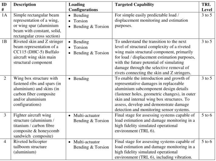
Table 1: SHM Platform Descriptions, Capabilities, and TRL Target
ID # Description Loading Configurations Targeted Capability TRL Level
1A Simple rectangular beam representation of a wing, or wing spar (aluminium beam with constant, solid, rectangular cross section)
Bending Torsion
Bending & Torsion
For simple easily predictable load / displacement monitoring and estimation purposes.
3 to 5
1B Riveted skin and Z stringer beam representation of a CC115 (DHC-5) Buffalo aircraft wing skin main structural component
Bending Torsion
Bending & Torsion
To understand the transition to the next level of structural complexity of a riveted wing main structural component, primarily for load / displacement estimation purposes, with the future potential of simulating damage through the selective removal of rivets connecting the skin and Z stringers.
3 to 5
2 Wing box structure with fastened ribs and spars (in aluminium) and skins (in carbon fiber composite and/or aluminium configurations)
Bending To enable the introduction and growth of representative damages in replaceable aluminium subcomponent design details (fastener holes, geometric changes), in outer skin and internal wing box structures. To assess, develop and demonstrate damage detection and monitoring sensor systems.
3 to 5
3 Fighter aircraft wing structure (aluminium / titanium / carbon fibre composite & honeycomb sandwich composite)
Multi-actuator Bending & Torsion
Final stage for assessing systems capable of load estimation and damage monitoring in a high fidelity simulated operational
environment (TRL 6). 5 to 6 4 Riveted helicopter tailboom structure (aluminium) Multi-actuator Bending & Torsion
Final stage for assessing systems capable of load estimation and damage monitoring in a high fidelity simulated operational
environment (TRL 6), including vibration.
5 to 6
Descriptions of the Test Platforms
The first test platform consists of either a simple aluminium beam with constant, solid, rectangular cross-section or a stiffened aircraft representative aluminium skin with riveted Z stringers, as shown in Figure 2. The test platform, through the use of up to four hydraulic actuators, can be used to evaluate load monitoring sensor and system capabilities in bending and/or torsion loading configurations, in quasi-static and low frequency conditions, simulating realistic loads and either constant amplitude or realistic operational spectra [9].
The second medium complexity structural platform is representative of a hybrid wing box with internal aluminium structure (ribs and spars) and composite material removable skins, with the capability to introduce / replace damaged structural components, such as aluminium internal spars, or aluminium skins,
6
as shown in Figure 3. Introduced damages can be grown with the application of either constant amplitude, or realistic and representative operational usage loading spectra. This test platform is dedicated to the evaluation of both load and damage monitoring / damage detection systems [10].
The third platform is able to apply simulated realistic flight loads in a controlled environment on a full scale F/A-18 aircraft outer wing box with up to 10 actuators, as shown in Figure 4. This platform includes the capability to incorporate damaged and undamaged components, with hidden damage already existing in the structural platform. These damages can be grown by applying variable loading spectra. This platform enables the assessment of both load monitoring and damage detection / monitoring technologies in a complex and realistic aerospace structure, in which existing damage locations and characterization is either not disclosed, or is not specifically identified to the sensor / system under evaluation.
The fourth platform is able to apply simulated realistic flight loads in a controlled environment on a full scale Bell 407 tailboom with up to six actuators, as shown in Figure 5. This platform enables the assessment of loads monitoring and damage detection / monitoring technologies in a complex and realistic aerospace structure and high fidelity simulated operational environment, including vibration. In all of these platforms, representative load conditions applied during full scale tests or observed during flight operations can be applied, ranging from static and quasi-static bending, torsion and coupled load conditions, to low frequency cyclic loading (constant amplitude and operational spectra), to higher frequency vibration associated with buffet and flutter. Several of these platforms also offer the opportunity to assess SHM systems capabilities to detect and monitor damage growth. This process is performed through the introduction of replaceable components with existing or artificially introduced representative damage [11].
Figure 2: Simple beam and Z stringer stiffened aircraft skin bending and torsion platform for evaluating load monitoring technologies.
Figure 3: A simulated wing box comprised of composite upper and lower skin with aluminium spars and ribs. Spars and substitute upper wing skins made of aluminium are replaceable.
7
Figure 4: CF188 outer wing spectrum loading full-scale test facility.Figure 5. Helicopter tailboom for assessing loads monitoring and damage detection / monitoring sensor performance under realistic flight loads.
Summary
The National Research Council Canada (NRC) completed a three year program, receiving financial support from the Department of National Defence (DND and more specifically AVRS-DRDC), where it designed, manufactured, assembled, instrumented, and characterized, both analytically, numerically and experimentally, four structural test platforms. A set of well characterized commissioned platforms, representative of the different complexity levels that can be found in current and future aerospace structures, were developed to enable sensor and technology assessment, development and demonstrations, in structured evaluations. The work also included the development, manufacture and characterization of undamaged and damaged replaceable elements that may or may not include discrete, multiple site, and multiple element damages. While these damages can be grown, both damage detection and load monitoring systems can be assessed through the application of realistic scale and representative load conditions and loading configurations.
8
Altogether, these platforms enable the evaluation of the applicability of sensor systems to the complexity of aerospace structures, not only in terms of sensor systems’ dimensions, weight, required power and most of all performance, but also opening ways to perform evaluations considering the aircraft environment, in terms of temperature, humidity, pressure and vibration. Beyond an important assessment of sensor and associated systems, this framework enables the evaluation and development of candidate sensor systems for a gradual implementation into full scale ground testing, as part of the design and development, and operation of aircraft and components, with the final objective of using sensors and associated systems in flight, both during testing and aircraft operation; prior to more complex introduction into aircraft flight testing.
These platforms are complete and are available to external parties, partners and clients, including aircraft and SHM equipment manufacturers, developers and users, to assess, develop and demonstrate the capabilities of equipment as a precursor to further development and implementation on actual flight aircraft. Future capabilities for including environmental effects relevant to aircraft service are being developed around these platforms to enable sensors and systems to be advanced through demonstrated trials further up the Technology Readiness Level (TRL) scale.
References
[1] http://ushistory4you.hubpages.com/hub/The-de-Havilland-Comet-Engineering-Disaster, last
accessed March 12th, 2013.
[2] JSSG-2006, Department of Defence Joint Service Specification Guide, Aircraft Structures,
30 October 1998.
[3] MIL-STD-1530C (USAF) Department of Defence Standard Practice, Aircraft Structural Integrity
Program (ASIP), 1 November 2005.
[4] http://www.holsip.com/,last accessed March 12th 2013.
[5] Ikegami, R., and Trego, A., 2000, “Structural Health Management: An Overview of Current
Research Efforts at Boeing”, ASM Aeromat Conference, Seattle, WA, USA.
[6] Speckmann, H., 2006, “Structural Health Monitoring (SHM): One Technology of the Airbus
Intelligent-Airframe Philosophy”, 2006 Asian-Pacific Workshop, Tokyo, Japan.
[7]
http://www.flightglobal.com/news/articles/airbus-and-boeing-back-structural-monitoring-212184/, last accessed March 12th, 2013.
[8] Mankins, Technology Readiness Levels in the National Aeronautics and Space Administration
(NASA): A White Paper, 1995.
[9] Beltempo, C.A., Yanishevsky M., Shi G., Martinez M., Rutledge R.S., Rocha B.,
Wickramasinghe, V. and Chen, E., 2011, “SHM Platform 1A Collaborator Information Package”, LTR-SMPL-2011-0255.
[10] Martinez, M., Beltempo, C.A., Yanishevsky, M., Shi, G., Rutledge, R.S. and Rocha, B., 2012,
“SHM Platform 2 Commissioning Package”, LTR-SMPL-2012-0085.
[11] Yanishevsky, M., Martinez, M., Mandache, C., Khan, M., Fahr, A. and Backman, D., 2010,
"Artificial Seeding of Fatigue Cracks in NDI Reference Coupons." Insight: Non-Destructive
Testing and Condition Monitoring – The British Institute of Non-Destructive Testing,
Vol. 52(12), pp. 664 – 671.
View publication stats View publication stats