Aseismic design of adobe housing
Texte intégral
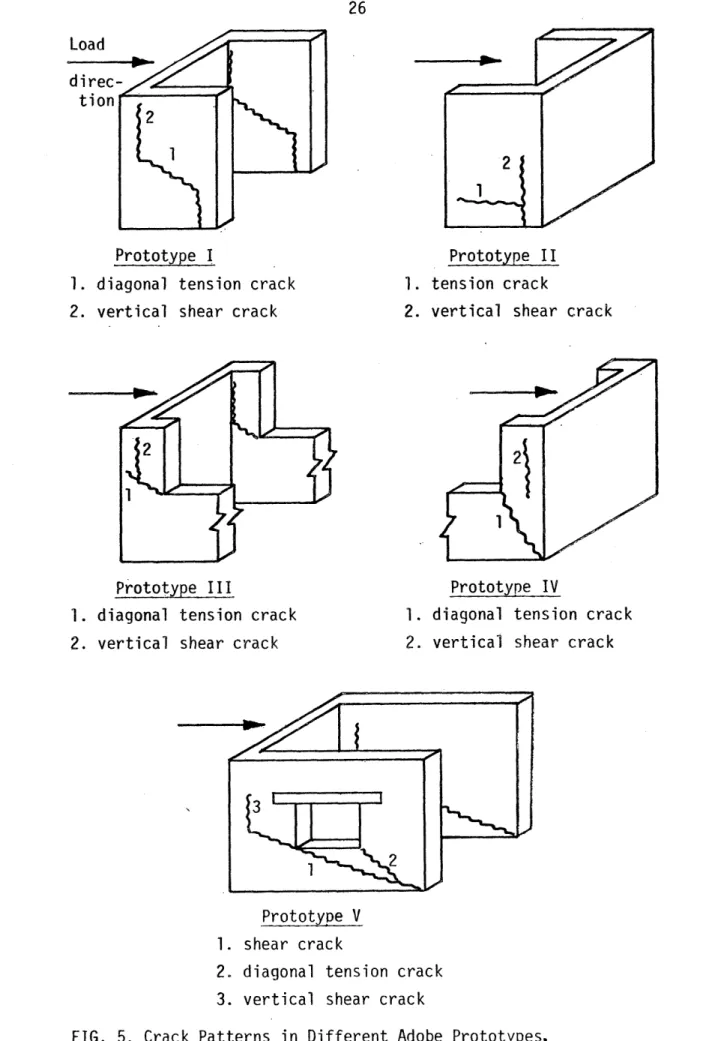
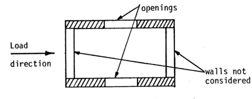
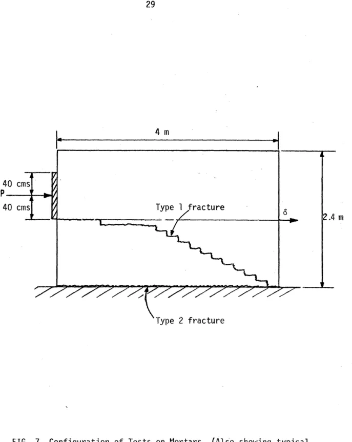
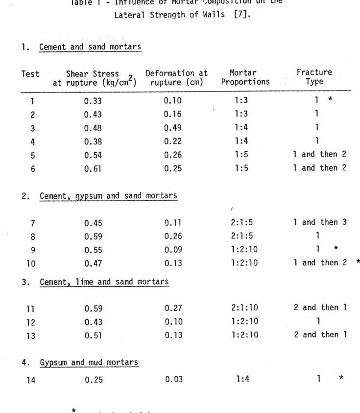
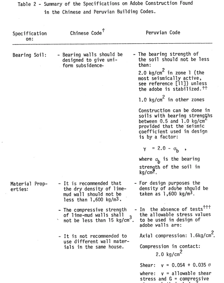
Figure

Documents relatifs
Another section will list the zone files to be loaded into the server for your local domain information.. A zone file typically contains all the data for a
by the AO system, and the resulting higher single-mode cou- pling efficiency. The improvement level, however, is lower than the predictions given in Fig. This may be explained by
They live in a lovely cottage in Stratford-upon-Avon, England. The house is not very big but my grandmother keeps it clean and tidy. It has only got one floor and the attic. In
A. To nd a zero of a maximal monotone operator, an exten- sion of the Auxiliary Problem Principle to nonsymmetric auxiliary oper- ators is proposed. The main convergence result
The continuous strength method (CSM) is a newly developed design approach, providing consistency with the observed stainless steel stress-strain response and allowing for
We would like to express our gratitude to all those involved in this project: artists, contributors and collaborators, the Avatar team, and in particular Mériol Lehmann,
47 ibid Nr 122, 18 (with the exception of the draft provisions on termination for compelling reasons).. This work is licensed under a Creative
focused on health assurance – if the industry and its leaders embrace transformation. With his extensive experience in medical education, universities and hospital system
