Cost Analysis and Comparison of Tray Container Style
Storage and Stackable Tote Style Storage
by
Youngjun Joh
Bachelor of Science in Mechanical Engineering Massachusetts Institute of Technology, 2016
Submitted to the Department of Mechanical Engineering in Partial Fulfillment of the Requirements for the Degree of
MASTER OF ENGINEERING IN ADVANCED MANUFACTURING AND DESIGN at the
MASSACHUSSETTS INSTITUTE OF TECHNOLOGY
June 2018
C 2018 Youngjun Joh. All rights reserved.
The author hereby grants to MIT permission to reproduce and to distribute publicly paper and electronic copies
of this thesis document, in whole or in part, and to grant others permission to do so.
Signature redacted
AuthorYoungjun Joh Department of Mechanical Engineering
CSignature
redacted
May16,2018 Certified by______________
L/ Maria Yang
Associate Professor of Mechanical Engineering & Engineering Systems Thesis Supervisor
Accepted by
Signature redacted
Rohan.Abeyaratne MASSACHUSETTS INSTITUTE Quentin Berg Professor of Mechanics
OF TECHNOLOGY Chair, Committee of Graduate Students
JUN
2 5 2018
LIBRARIES
ARCHIVES
Cost Analysis and Comparison of Tray-Based Storage and Stackable Tote
Storage
by
Youngjun Joh
Bachelor of Science in Mechanical Engineering Massachusetts Institute of Technology, 2016
Submitted to the Department of Mechanical Engineering on May 16, 2018 in partial fulfillment of the requirements for the degree of
Master of Engineering in Advanced Manufacturing and Design
Abstract
With the emerging interest in automated distribution centers, shelves operated by mobile robots are also rising in importance. This paper focuses on comparing the cost of two potential shelf designs for storing product in an automated distribution center, a tray container style shelf and a stackable tote style shelf. Tray container style shelf has lower manufacturing costs, assembly cost and time, while stackable tote style shelf had competitive edge on packaging and shipping costs, and space utilization. The manufacturing cost, packaging cost, and shipping costs $174.44, $59.77, and $39.04 respectively for tray container shelf, and $380.83, $25.98, and $16.9 for stackable tote shelf. The assembly time and space utilization were 8 minutes and 81.5% for tray container shelf, and 17.2 minutes and 84.4% for stackable totes. Overall, stackable tote shelves cost 55% more, but have 2.9% space utilization
Acknowledgement
First I would like to thank my parents for supporting me both financially and
mentally. Special thanks for my mom for asking my prayer requests and praying for me every other week, and to my dad who reassured me when I was a little panicking due to slow progress in my dissertation.
Also thanks to the MIT teammates, Ben Schilling, Barbara Lima, and Jody Fu for brainstorming different concepts together, clarifying our understanding of the design, and helping out with analysis. Special thanks to Ben Schilling for driving us to Company X, our project site multiple times every week, to Barbara Lima for being awesome at keeping our schedules and contacting company people through email, and to Jody Fu for giving insights in the design process.
From the MIT staff, I would like to thank Professor David Hardt and Jose Pacheco for organizing this MEngM program, allowing me to get a deeper understanding in statistical processes and a taste of entrepreneurship and supply chains. Special thanks for Jose Pacheco for mentoring me when I was mentally fatigued. Also I would like to thank my thesis advisor, Professor Maria Yang, for guiding me in writing the dissertation.
Many thanks also to the Company X staff, specifically to Peter C. and Yvetta S. Peter has helped our team decide on the thesis project, and let us investigate the projects on our own pace, as well as setting us an advisor to help us throughout the project. Yvetta S. was a very supportive advisor, providing us lots of resources to understand the project from a bigger picture, as well as giving constructive feedback on what we may have missed. Also I thank David A. for helping out FEA; Stephen H. for helpful feedback in manufacturability of our design; Kristy D. and Kunal C. for emphasizing us the importance of assembly; and Minh L. for giving us insight in how packaging can be impactful, and helping us greatly with the estimated packaging and logistics costs for both designs.
Table of Contents
A b str a c t...3 A cknowledgem ent...5 List of Figures...9 List of Tables ... 10 1. Introduction...112. Background Inform ation ... 12
2-1. A utom ated Distribution Centers ... 12
2-2. Requirem ents and Specifications... 13
3. Tray Container Style Shelf Design ... 15
3-1. Original Design...15
3-2. Problem s of the Original Design... 17
A ssem bly ... 17
C o st ... 17
W eight ... 17
3-3. Suggestion for Design Change ... 18
Fewer Parts ... 18
Less On-site A ssem bly ... 18
N o Corrugated Side W alls... 18
4. M odified Tray Container Shelf Design ... 19
4-1. Proposed M odified Design ... 19
4-2. M odification Process ... 21
4-2a. A ssem bly Sim plification ... 21
4-2b. Sim plified M odel Verification ... 23
4-2c. Optim ization...26
5. Stackable Tote Style Design ... 28
5-1. Concept D evelopm ent... 28
5-l a. Early Prototypes ... 28
5-lb. Concept Generation... 29
5-2. Proposed Design ... 31
5-2a. Alum inum Plate...31
5-2c. Hinge Connection... 33
6. Com parison of Tray Container and Stackable Shelves... 34
6-.1. Cost ... 34
6-la. M anufacturing Cost... 34
6-lb. Packaging and Shipping Costs ... 37
6-1c. A ssem bly Tim e & Cost ... 41
6-2. Space Utilization...45
7. Conclusion ... 46
List of Figures
Figure 1. Kiva Systems developed the first mobile robotic fulfillment system ... 13
Figure 2. Concept Drawing and CAD of Tray Container Shelf ... 15
Figure 3. U-Shaped Connector and Horizontal Sheets Fixing the Side Walls ... 16
Figure 4. Proposed Improved Design and Its Features ... 19
Figure 5. Original model and simplified model for easier assembly ... 21
Figure 6. FEA results of Corrugated Walls and Square Tube Posts ... 22
Figure 7. Simplified Skeleton Model for Quick FEA Analysis ... 23
Figure 8. Material change impact on deflection ... 24
Figure 9. Geometry change and its impact of deflection ... 25
Figure 10. FEA results of tray ... 27
Figure 11. Sheet Metal 4-Pin Stackable Prototype CAD ... 28
Figure 12. Sliding Tote Design ... 30
Figure 13. Fully Assembled Stackable Tote ... 31
Figure 14. 1.5mm Aluminum plate with center divider ... 32
Figure 15. Chamfered Rails and Inserts ... 33
Figure 16. Hinge with Self Tapping Screws, Folded Wall Assembly ... 33
Figure 17: Tray Post Nested Configuration ... 37
Figure 18: Corrugated Wall and Top Lid Nested Configuration ... 38
Figure 19: Tray Stacking Configuration ... 38
Figure 20: Foldable Totes in Shipping Configuration ... 39
Figure 21: Bottom Totes Stacked in Shipping Configuration ... 40
Figure 22: Stacked Aluminum Plates ... 40
Figure 23: Tray Container Shelf Assembly Order ... 42
Figure 24: Stackable Tote Shelf Assembly Order ... 43
List of Tables
Table 1. Functional Requirements ... 14
Table 2: Corrugated Back Wall Location and Max Stress and Deflection ... 26
Table 3: Tray Container Shelf Manufacturing Cost ... 35
Table 4: Stackable Tote Style Manufacturing Cost ... 36
Table 5: Packaging and Logistics Cost for Tray Container Shelf ... 39
Table 6: Packaging and Logistics Cost for Stackable Tote Shelf ... 41
Table 7: Tray Container Shelf Onsite Assembly Time Estimation ... 42
Table 8: Stackable Tote Shelf Onsite Assembly Time Estimation ... 44
Table 9: Space Utilization Comparison of Stackable and Tray Shelf ... 45
1. Introduction
The purpose of this thesis is to compare two potential designs of storage shelves in an automated distribution center, analyze its impact in terms of time and money, and decide which has more potential to efficiently maximize storage space utilization. Specifically, this thesis would compare the manufacturing costs, shipping costs, assembly time and cost, and space utilization of two designs: a modified version of an existing tray container style design and a novel stackable tote style design. The scope of this thesis is not on full optimization or designing a market-ready product, but rather is on the comparison of two relatively optimized prototypes at a ballpark to suggest which design has more potential to be cost-competitive in the long run.
Section 2 will discuss background information of distribution centers and their storage system. This section would include how automated distribution centers work, as well as key concerns and difficulties in distribution centers. An overview of the requirements and specifications of a storage shelf is also included here.
Section 3 will introduce and analyze an existing tray container style design, and identify its key problems. At section 4, this design will be slightly modified for better manufacturability and assembly. This section will also include what were the key design considerations and rationale for such changes.
Section 5 will introduce the stackable tote style design. Some early prototypes and their problems will be identified, and then the concept generation phase would be walked through. Finally, a conceptual design that considers manufacturability, assembly, and scalability would be elaborated.
Section 6 will compare these two styles in terms of cost and space utilization. Major cost considerations are the manufacturing cost, packaging and shipping costs, and assembly costs. Space utilization would consider how efficient each design is in using a given amount of space.
Section 7 will summarize the whole thesis and make a conclusion on which design is more preferable, based on section 6. Future works will also be discussed in this section.
2. Background Information
2-1. Automated Distribution CentersA distribution center, also known as a fulfillment center, is a warehouse of a variety of products that connects suppliers and consumers. The amount and variety of the product stored in distribution centers depends on the demand or expected demand of consumers. The goal of a distribution center is to store enough safety stocks of goods, and ship goods to customers as quickly as possible.
There are three main sections in a typical distribution center: the receiving dock, the storage area, and the shipping dock. At the receiving dock, goods are received and sorted according to their characteristics, and sent to the storage area. At the storage area, these goods
are stored in designated locations, according to their category. Items are also sent to the shipping dock if they are demanded. Lastly, shipping docks package and ship the goods to retail stores or independent customers.
Two most important considerations in a distribution center are space utilization and storage management. This is especially a big problem for large distribution centers, where there are a myriad of items to sort. Sorting each item by types and sizes would cause huge bottlenecks in the sorting stage at the receiving dock, while random storage after individual identification can cause problems in the shipping stage. In terms of space utilization, narrow spacing between containers increase packing efficiency, but at the same time hinders access to the stored products.
These two problems have been alleviated by robots. Instead of having people walk across the distribution center to access shelves, robots will move the shelves to the people, who could quickly package goods and send them to the shipping dock. Kiva Systems, now known as Amazon Robotics, was the first to develop such mobile robotic fulfillment system, which started the idea of automated distribution centers. These autonomous mobile robots are able to orient themselves using fiducial markers placed on the floor, track the target shelf based on information in the system server, moves the shelf to a station for a worker, and puts the shelf back after goods are taken out. This not only reduced the cycle time between getting an item and shipping it, but also increased packing efficiency, as shelves can be stacked without considering human access.
< Figure 1. Kiva Systems developed the first mobile robotic
fulfillment system. >
Although Amazon Robotics have kept this technology for internal usage only, other competitors like the GreyOrange Butler and the Swisslog CarryPick have been emerging to provide similar services. With the dissemination of such technology, the warehouse industry is expected to adopt the technology, given the benefits it could provide. The two shelf designs to be discussed later in this thesis are specifically designed for such automated distribution centers, where shelves are expected to be moved by mobile robots.
2-2. Requirements and Specifications
Shelves in automated distribution centers are expected to have different requirements and specifications than shelves in traditional distribution centers. They should be capable of withstanding both static and dynamic load, and should prevent items from slipping off.
The following page lists the requirements and specifications of a mobile shelf. These requirements are made based on a tray container style design, but similar requirements have been considered when designing the stackable tote style design as well. These requirements would be the standard of comparing the two designs in this thesis.
Category Functional Requirements Condition Value
Assembly Assembly time < 20 minutes
Time to learn assembly < 1 hour
Assembly tools = Manual labor standard
tools
Shelf Life Shelf / Tray Life > 7 years
Tray removal-insertion without > 9,000 cycles
maintenance
Shelf handling tray removal-insertion > 1,000,000 cycles without maintenance
Cost Total cost of shelf + trays < 200% of normal shelves
in distribution centers
Loads Tray load capacity > 555 N/m2
Shelf load capacity (include shelf) > 750 lbs
Interference Shelf sway < 1 inch
Shelf overhang = No protrusion of tray or
items beyond shelf face
Tray interference = No contact of product
with tray above
Tray Tray height = Fixed height variations
Tray lip height > Tall enough to prevent
product falling off
Tray swapping = Compatible trays
< Table 1. Functional Requirements >
The key design considerations given these requirements were quick and easy assembly, low cost, high static and dynamic stability, and light weight. Quick assembly and low cost are critical as distribution centers are going to use thousands of these shelves. Static stability is obviously essential to function as a container, while dynamic stability is important as it affects the packing efficiency and maximum acceleration. Lastly, light weight is
important since distribution centers want to pack as much goods as possible in a single shelf. If the shelf itself is too heavy, then items can be weight-limited instead of being space-limited, due to the limited power of autonomous mobile robots.
3. Tray Container Style Shelf Design
3-1. Original Design
I
I
< Figure 2. Concept Drawing and CAD of Tray Container Shelf >
Based on the requirements given above, a prototypical shelf had been designed and tested. Figure 2 shows a concept drawing and the 3D model of the prototype. This prototype has 42 metal trays with 5 different virtual tray heights, which is the height from the floor of one tray to the floor of the tray above. These virtual tray heights were determined based on an optimization analysis to minimize unused volume above each item in a container. Each of the trays is supported by two rails, which are riveted against the side walls. The trays are held in the shelves by two magnets attached at the back of each rail. Some of the trays have vertical dividers, but this would be ignored in this thesis.
The base of the shelf is made with welded steel square tubes, and is high enough for mobile robots to drive under. The side walls are corrugated to provide rigidity in the up-down direction and front-back direction, and have holes to reduce weight. The center wall is also
corrugated, but is thinner than the side walls. These corrugated walls are fixed relative to the four-legged metal base by small, thin metal connector pieces shown on Figure 3 (left), and are fixed relative to one another by three horizontal metal sheets and the top lid, as shown in Figure 3 (right). All of the components except the trays are made of steel. The whole shelf weighs about 350 lbs.
Static and dynamic tests were done on this prototype. For static testing, the trays withstood 700 N/M2 without much deformation, well exceeding the required load capacity of
555 N/M2
. The shelf was also fine holding up to 1000 lbs of weight, including its own weight. Dynamic testing was performed by using an actual mobile robot to move the tray container shelf. Shelf sway data was collected by using motion capture cameras and measuring the sway deflection through video analysis. The largest sway deflection for this prototype was 20mm in the left-right direction and 4mm in the front-back direction.
-I-
-U-< Figure 3. U-Shaped Connector (left) and Horizontal Sheets Fixing the Side
I
3-2. Problems of the Original Design
The original design had multiple problems despite its successful performance in static and dynamic tests. The three main problems are: difficult assembly, high cost, and heavy weight.
Assembly
The first and biggest problem is its difficult assembly. Because the prototype was not meant to be scaled to production, a lot of its features were not designed for assembly. The biggest issue is its excessive use of rivets. Although the base came pre-assembled from the manufacturing side, all other parts were independent pieces that were assembled on site. This not only increases the assembly time, but also affects the quality control of each shelf, as the workers in the distribution centers are less skillful than professionally trained assembly workers in the supplier side.
Each rail is fixed to the corrugated side walls with multiple rivets, and with 84 rails, that already requires hundreds of rivets. Moreover, because the corrugated side wall and the center wall are completely vertical, they need supplementary connectors (Figure 3) to be fixed relative to the base and the top lid, which are both horizontal. With multiple supplementary connectors inside and outside, a single tray container shelf requires 1,200 rivets and hours of assembly time. Worse still, the rivets are not standard sizes and require expensive custom rivet guns. Having 2 magnets to be attached at the end of each rail also makes assembly time longer.
Cost
The cost of each tray container shelf was a few thousand dollars, much higher than the requirement. Not only are the corrugated walls costly, but the cost of 1,200 rivets adds up to a significant amount. The magnets holding on the trays are also very expensive. The long assembly time also affects the total cost directly and indirectly, through additional labor costs and a long lead time. Considering that many distribution centers have tens of thousands of shelves and containers, a single shelf taking multiple hours of assembly time would be the main bottleneck and delay the opening of a distribution center.
Weight
Weight is another problem of this prototypical tray container shelf. With the
additional weight, there is more possibility that the shelves may not operate with full capacity due to the weight limit the mobile robots could handle. Heavy weight also makes assembly
more difficult, as it is hard to move the shelf in an assembly-friendly position for the workers.
3-3. Suggestion for Design Change
The current prototype shows that a tray container shelf is possible, but not plausible for scalability. In order to solve the critical issues of assembly, cost, and weight, three basic changes are suggested: Fewer parts, less on-site assembly, and no corrugated side walls.
Fewer Parts
Currently, each side wall requires 21 rails and five connectors, which respectively requires six and nine rivets. The left wall, the right wall, and the center wall look very similar but are unique pieces, and they require 3 different types of connectors. Having many parts means longer assembly time, and similar looking unique pieces can cause confusion in assembly. Instead, a better design would have fewer parts that are compatible. If they need to be unique, the difference should be conspicuous so that workers would not waste time or
make mistakes.
Less On-site Assembly
On-site assembly adds a lot of flexibility, but sacrifices lead time and product quality. Since flexibility is not so important in large distribution centers, shipping pre-assembled parts would be more productive. Of course, shipping fully assembled tray container shelves would eliminate assembly time completely, but vastly increase shipping costs and cause a new bottleneck in the shipping stage, as thousands of trucks would need to ship whole shelves. Therefore a nice balance of upstream assembly and on-site assembly is needed.
No Corrugated Side Walls
The bulk of the weight in the tray container shelf is in the base, the trays, and the corrugated walls. However, whereas the weight of the base adds stability and the weight of the trays are inevitable, the corrugated side walls add a lot of weight without much benefit. Although it adds a lot of rigidity, it only adds rigidity in the front-back direction, which is already somewhat supported by the rails. Moreover, the rigidity in the front-back direction is overwhelming. Although the corrugated walls reduce sway in the front-back direction to an impressive 4mm, the shelf-to-shelf clearance is dominated by the 20mm sway in the left-right direction. Therefore, the impressive front-back direction rigidity has no impact on the actual performance. So instead of a corrugated wall, a simpler and cheaper structure can be considered.
4. Modified Tray Container Shelf Design
4-1. Proposed Modified Design
/4
00,,
1
< Figure 4. Proposed Improved Design with Corrugated Back Wall (1), Center post riveted
on base (2), single piece top lid (3), and
flat
springs (4)>Based on the concerns of assembly time, overall cost, and shelf weight, the design in Figure 4-(1) is proposed. There are four main features: pre-assembled railed posts, single-piece top lid, a corrugated back wall, and flat springs.
The railed posts replace the corrugated side walls, individual rails, and all the connector pieces that fixed the corrugated wall against the base. The steel posts are hollow square tubes, which can be inserted into the hollow legs of the base and then riveted. The center post has a small extended part that can be inserted into the base and be riveted, as in Figure 4-(2). These steel posts have the rails spot-welded at the manufacturing site, which eliminates the on-site riveting. Although this would increase the manufacturing cost, it would cut the on-site assembly time and cost drastically. Considering there are 8 rivets per rail, this takes away 672 rivets, which could take 3O~6O minutes depending on how skilled the worker is. Though the steel posts by itself do not provide much resistance to sway, the welded rails
makes the whole structure much more rigid in the front-back direction, compensating for the loss of rigidity by replacing corrugated walls.
A single-piece top lid is used instead of the previous 3-piece top lid. The new lid would be a bended 2mm aluminum sheet, with a 10 degree draft angle to allow it to be nested when packaged and shipped (Figure 4-(3)). Since it is a single piece, extra rivets to connect the three pieces together is not necessary anymore. It is also stronger than three individual pieces held together with a few rivets. However, despite its draft angle, it has higher
packaging and shipping costs, since three flat plates can be packed much more densely than a C-shaped metal sheet could.
A corrugated back wall is added for support instead of having three separate thin plates at the top, middle, and bottom. This saves assembly time as it decreases the number of individual parts and rivets. Since the back wall is corrugated, it adds more rigidity in the side-to-side direction than a thin plate would.
Lastly, flat springs are used instead of magnets to hold the trays, as in Figure 4-(4). The springs would just compress the tray sides, and keep them stable with friction. Since they are merely bent metal sheets, there is not much concern of mechanical fatigue or failure. Frictional wear may be an issue, but these springs would be very easily replaceable. Most importantly, the manufacturing cost of a flat spring is much cheaper than a magnet. Assembly time would be the same, but just like the rails, assembly of these springs could be done upstream in the manufacturing site.
Overall, these changes reduce assembly time significantly by having as many parts pre-assembled in the manufacturing site, and also reduce some of the cost by minimizing the number of parts and rivets. Only 40 rivets are used, which is 3.3% of the original 1,200 rivets. Therefore, assembly time is expected to reduce by at least an order of magnitude.
4-2. Modification Process
The modified design was designed in 3 steps. First, a rough design that simplified assembly was considered. Out of the three major concerns, assembly was the most important and yet the most difficult aspect to tackle. Cost and weight could be reduced relatively easily even after a design direction has been decided upon, but assembly seemed more
fundamentally linked with the shelf design.
After starting with an assembly-simplified design, a simplified skeleton model was used to quickly confirm various features and how it impacts the overall performance of the shelf: rigidity, assembly, and weight. Finite element analyses were performed to check the rigidity. After more detailed features were determined, further analysis was done to optimize some of the dimensions. Since this thesis is focused upon a relative comparison of two designs, only some parts of the designs were optimized.
4-2a. Assembly Simplification
< Figure 5. Original model (left) and simplified model for easier assembly (right) >
The first approach was to make assembly simpler. Instead of using corrugated walls which required multiple connector pieces, steel posts were considered as they could be inserted and riveted directly onto the base. The steel plates that barred across the three corrugated walls were taken away, since each of them required 6 to 9 rivets. The top lid was modeled as a single-piece trapezoid box, which is not realistic but easy to model and analyze.
Once a simplified model was created, FEA was done to compare the stiffness of the simplified design to the original tray design. Not only could this tell how much less rigid the simplified design is compared to the original design, but it could actually help estimate how much sway the new design would have in reality. We could assume that if FEA results show that the original design is 3 times stiffer in the front-back direction, then actual sway would be roughly 3 times less.
However, despite multiple trials, the original model failed to simulate properly due to its complexity. Therefore actual data was not directly comparable with simulation results. Instead, just the two side walls were compared to get a general understanding on the stiffness difference. Figure 6 shows FEA results of a corrugated side wall and steel posts with rails. The base was fixed, and loading condition was 250N horizontally, a force equivalent to the average weight of items at the maximum acceleration of a typical mobile robot.
I 00t -000 91 ,000 ?93%0 00; 323e2--OD 2.74 1*-CW 3.290it001 13M.e001 5A202 1000. 030 1 OODe 030
FEA results showed that a single corrugated wall was 40% more resistant to left-right direction sway, deflecting 30mm, compared to the 50mm of the railed posts. This difference would reduce as other supporting parts like the top lid are almost identical in rigidity. However, considering that the original corrugated wall design swayed about 20mm left to right, barely under the 1 inch (25.4mm) requirement, the simplified railed design would need to have additional parts to strengthen rigidity in the left-right direction.
Meanwhile, the corrugated wall was 140% more resistant to the front-back direction sway, as shown in Figure 6. Despite this large difference, the corrugated wall prototype had only swayed 4mm in the front-back direction, thus an additional 140% sway would still be less than 10mm. Therefore, the railed steel posts are expected to meet the 1-inch sway requirement in the front-back direction.
4-2b. Simplified Model Verification
< Figure 7. Simplified Skeleton Model for Quick FEA Analysis >
Understanding that there is enough rigidity in the front-back direction, a simpler skeleton model was considered to quickly iterate different design features and their effects. All of the rails were removed, leaving only the base, 6 posts, and the top lid. Static FEA was
used to compare how this removal affected the overall rigidity. The same fixtures and loading conditions were applied: The base was fixed at the center cross, where the mobile robots contact, and 250N of force was applied to the side.
FEA results showed that there was a huge difference of 802% in the front-back direction sway due to the rails, but only 15% difference in the left-right direction sway, as the rails do not play a significant role in adding rigidity in that direction. This suggests that the skeleton model can be used to understand left-right direction sway of the simplified railed design. Since the sway is greater in the skeleton model, any promising FEA result in the skeleton model was assumed to be also promising in the simplified railed design. Based on this assumption, material and geometry changes were made.
Material Change
I
.MM 1 41<A460 F-ON
Lef: op .d Cete:To id+ ts ightpLd+Bs>
MtIh-g sws sti
s , i s
M ighr d
I Cox X. C
< Figure 8. Material change from AJSI 1020 to 6061-T6 and its impact on deflection.
Left: Top Lid, Center: Top Lid + Posts, Right: Top Lid + Base >
Material change from carbon steel to aluminum was tested. Whereas carbon steel is stiffer, aluminum is 3 times lighter, and the loss in weight may have more value if the loss of
rigidity is not too great. Based on FEA results on the skeleton model, changing the top lid from carbon steel to aluminum sacrificed rigidity by 2.2%, but reduced the weight of a medium load tray container shelf by 3.5%. On the other hand, changing the base or post material into aluminum resulted in 150% and 16.5% increase in deflection with only 4~5% decrease in medium loaded shelf weight. Therefore, other than the top lid, the material of the base and the posts should remain carbon steel.
Geometry Change
I
< Figure 9. Geometry change and its impact of deflection.
back (right). >
Full back (left) and corrugated
Previous FEA results showed that the simplified railed design needed additional stiffness to resist left-right sway. A quick FEA was done to see the impact of a back wall, shown in Figure 9 on the left. A full back support increased stiffness by 7 times, which would meet the requirements of 1 inch sway. However, the model was assuming the back support and the top lid was a single piece, which would be a bad design in terms of manufacturing, packaging, and assembly. In the next design iteration, it was split into two pieces-a single-piece top lid and a long back plate that could be riveted. FEA result of this modified design was not achieved; the simulation stopped amid due to buckling failure.
Buckling failure could be avoided by thickening the back wall, but this would add weight drastically, and also sacrifice usable space. Therefore a corrugated back wall was considered. This still sacrifices usable space, but weighs even less than the previous full back wall. FEA result showed that the tray container shelf with a corrugated back wall was 4 times stiffer in the left-right direction sway than the simplified rail design.
25 I701.4000 SAM 400, 7 2"t 30, 146t X ,t~ )W -______
~1
4 IPIS We"1 *12V.001 ( 37'% 001 A N910 0014-2c. Optimization
Corrugated Back Location
So how much corrugated back support do we need? There are multiple possible optimizations-wall height, groove depth, groove width, material thickness, and wall location. In this thesis, only one of them was examined: wall location. A 206mm height, 0.725" groove depth, 0.05" thick corrugated back support was placed at different heights from the base, where 0mm means it touches the bottom base, and 1498mm means it touches the top lid. Then the sway simulation was done under the same conditions as previous FEAs, with the base fixed and 250N applied to the side. Table 2 shows the maximum stress and deflection according to where the corrugated back support was located.
Distance from Max Stress Tip Deflection
Base [mm] [MPa] [mm] 0 219 8.5 250 270 8.37 500 288 7.78 750 309 7.62 1000 324 7.93 1250 332 8.6
< Table 2: Corrugated Back Wall Location and Max Stress and Deflection >
Results show that there is minimum deflection when the corrugated back support is placed 750mm away from the bottom base, while maximum stress increases as it is placed further up. This is because more deflection causes more strain and stress for the corrugated back wall. Since the distance from the bottom base to the top lid tip is 1498mm, having a minimum deflection at 750mm suggests that there is minimum deflection when the wall is placed at the center.
Tray Material and Thickness
< Figure 10. 7mm ABS-PC tray with 1.36mm deflection (left), 1.6mm 6061-T6 tray
with 1.26mm deflection (right) >
Tray material and thickness were also tested. Two types of material were considered, ABS-PC and 6061-T6. The previous design used 4.76mm ABS-PC for the trays, which would deflect 4.12mm under the required tray load capacity of 555N/m2. This means just by the tray thickness and deflection, almost 9mm of vertical space is wasted. A 7mm ABS-PC tray would deflect only 1.36mm and wastes 8.3mm of vertical space (Figure 10 left), but each tray would weigh 8.47 lbs, 45% more than the previous 5.83 lbs.
On the other hand, an aluminum tray would add far more rigidity without adding too much weight. A 1.6mm aluminum tray would only deflect 1.26mm, thus only losing 2.86mm of vertical space per tray. Furthermore, it also reduces wasted space horizontally, as the side walls would also be thinner. Overall, a 1.6mm aluminum tray would have 78.7% space utilization, increasing space utilization by 10% compared to 71.9% and 71.4% of the 4.62mm and 7mm ABS-PC trays. Even in terms of weight, it weighs 4.98 lbs, 14% lighter than the previous ABS-PC tray.
5.
Stackable Tote Style Design
5-1. Concept Development5-1a. Early Prototypes
< Figure 11. Sheet Metal 4-Pin Stackable Prototype CAD >
While improving the original tray container style shelf design, an alternative design was considered and developed. Figure 11 shows the CAD model of an early model of stackable tote style design, which was motivated by trying to increase space utilization by getting rid of the external structure. This sheet metal stackable prototype had 4 thin metal pins, upon which the totes were stacked. However, the biggest problem was aligning the 4 pins. Not only were the totes huge compared to the pin size, but they were also quite wobbly because they were made out of thin sheet metal. Since the tote needs to meet the 1 inch sway requirement, the pins were designed with very tight tolerances, making it even harder to align the pins. Having pins also made it harder to access the items inside. Instead of simply sliding out a tray, each tote had to be lifted before the items could be accessed.
Furthermore, these stackable totes were not designed for shipping or assembly. If pre-assembled totes were shipped, then the shipping costs would skyrocket as a lot of empty space would be shipped. On the other hand, if each side walls were to be shipped separately, welding and riveting each wall on site would require a lot of assembly time and special tools. Both cases are not desirable.
A second prototype was developed with the goal of improving the alignment issue while minimizing weight. Instead of stacking with a pin-and-socket mechanism, a bigger rectangular insert like gear teeth was implemented. These inserts had draft angles to guide the totes together so that alignment was easier, while the rigidity is not sacrificed with loose tolerances. Also, instead of using thin metal sheets, which makes the overall structure less rigid due to its low width-to-thickness ratio, the prototype was made with plastic. This sacrifices some of the space utilization, but it can increase stiffness and allow complex parts to be manufactured using injection molding. In order to increase the weight-to-stiffness ratio, each of the plastic walls was ribbed. The walls were also easily assembled by a snap-fit feature. This plastic prototype seemed more promising in terms of alignment and assembly, but its structural strength and manufacturing costs were still questionable.
5-1b. Concept Generation
Based on these two prototypes, our team worked on brainstorming concepts for the stackable tote style design. Instead of brainstorming a full design, each feature was separately brainstormed and evaluated based on five different categories. The five categories were
shipping, assembly, stacking mechanism, locking mechanism, and product access. Shipping considered how the stackable tote style shelf would be shipped to the distribution centers. This category considered nestable or collapsible features that improved packing efficiency. Assembly considered various on-site assembly methods such as spot welding, riveting, keyhole slots, or snap-fits. Stacking mechanisms and locking mechanisms considered how each tote would be stacked on top of each other, and how they would stay fixed relative to each other after being stacked. The locking mechanism was important, as the totes would need to stay stacked even when the mobile robot moves the stackable shelf. Lastly, product access considered how each tote would be taken out of its stacked state so that the products inside could be accessed. The details of the concept generation and design iterations are articulated in a separate thesis, The Design Process, Manufacturing and Cost Analysis of Modular and Stackable-based Storage Units written by Jody Fu.
In the early stages, sliding stackable totes were considered. These totes would simply have integrated rails, and products would be accessed just like from a typical drawer. This concept was appealing not only because it allows easy product access, but also because it
could save vertical space of the distribution center, as lifting is not required. A pin-and-socket style stacking mechanism would require some extra space above the shelf so that the totes can be lifted up and removed. This means for a multi-story distribution center, the space utilization decreases. Also, with the sliding mechanism, alignment is much easier than the 4-pin design, as you only need to align two surfaces instead of four points. Assembly was expected to be relatively easy as well by having modular parts that could snap-fit together
like Lego pieces (Figure 12 top).
However, after multiple design iterations, this idea was abandoned due to difficulties in the locking mechanism. Whereas the sliding motion made product access easy, it also meant that the totes needed a separate locking mechanism both front and back. And since each tote lock interferes with the motion of the totes above and below, at least 4 individual locking mechanisms at the front and back of both top and bottom needed to be engaged and disengaged to slide out a single tote (Figure 12 bottom). This complexity in the locking aspect made the benefit in easy access obsolete.
5-2. Proposed Design
< Figure 13. All Fully Assembled Tote for 1 Shelf (top), Fully Assembled Tote (bottom) >
Ultimately a lift-and-slide concept was chosen for this cost analysis. The general concept is similar to the purely sliding drawer concept, but the main difference is that the totes need to be lifted a little before it could slide out. Each tote is consisted of an aluminum plate, two sets of walls, and hinges.
5-2a. Aluminum Plate
Metal plates have been used in previous stackable shelf prototypes, as plastic floors needed to be thicker to sustain product weight, which decreases space utilization. Aluminum is light enough and much stronger, thus higher space utilization could be achieved with even lighter weight. Although steel is stiffer, aluminum plates only needed to be 1.5mm thick, therefore changing it to steel did not add much space utilization. Based on FEA results, a
1.5mm aluminum plate only drooped 0.6mm when 555N/m2
of pressure was applied. This was far less than the 5mm droop requirement.
< Figure 14. 1.5mm Aluminum plate with center divider >
The final design of the aluminum plate includes a small divider in the center (Figure 14). This divider allows products to be more organized, and also adds more stiffness in the center area. This channel has a 15 degree draft angle so that the plates could be nested. This 30 degree draft angle allows it to be nested with 0.125 inch separation.
5-2b. Side Wails
The tote is consisted of two sets of walls: the railed side walls and the place-holder front and back walls (Fig 13). The front and back walls only exist to keep the products inside the tote; they do not support the vertical load of the totes above nor prevent the whole shelf from swaying. Most of these are done by the side walls.
Guiding Rails
The side walls act both as a guiding rail and a slider. The top of the side wall has an external lip, while the bottom of it has an internal lip. These interact with each other as rails once the totes are stacked so that each tote can slide relative to each other without an external structure. The top and bottom lips are long enough so that the tote can still be guided after being lifted up from the chamfered insert. This guarantees vertical alignment of the totes. The guiding rails are thickened enough so that they could resist swaying once the shelf is
accelerated by mobile robots.
Chamfered Inserts
The side wall has multiple chamfered parts to ease alignment of the totes. At the end of the top and bottom lips are chamfers, as in Figure 15. These chamfers help horizontal alignment of the totes after they are removed from the stack and need to be re-inserted.
of chamfered inserts. These act as a pin-and-socket style locking mechanism, fixing the totes horizontally. The chamfers help the totes to easily align themselves into the right positions. At the same time, this takes most of the vertical load, therefore requires a lot of thickness.
< Figure 15. Chamfered Rails and Inserts >
5-2c. Hinge Connection
Lastly, all the walls are connected to each other with hinges that could rotate 360 degrees. The hinge would be screwed onto the plastic walls with self-tapping screws, as in Figure 16 (left). Although this feature requires more parts, it is far more reliable that snap-fits, whose performance may vary greatly depending on the feature quality. More importantly, the 360 degree rotatable hinge allows the walls to be stacked in an assembled state. This means assembly time can be greatly reduced, while also keeping the packing efficiency when
shipping.
< Figure 16 Hinge with Self Tapping Screws (left), Folded Wall Assembly (right) >
6. Comparison of Tray Container and Stackable Shelves
The former sections discussed about the development of the design of the tray
container style shelf and the stackable tote style shelf usable in automated distribution centers. Both designs were not fully optimized for performance, but designed for better assembly and manufacturing. This section focuses on comparing the cost and space utilization of the two designs. The cost will cover manufacturing, packaging, shipping, and assembly costs, while space utilization will discuss the maximum space each shelf could utilize.
6-1. Cost
6-1a. Manufacturing Cost
Manufacturing costs were estimated by the material costs of the components. These components are expected to be produced in millions, as a single distribution center can often hold thousands of shelves. At a large scale, most components would cost about 10-20% more than the pure material cost, unless the manufacturing process is complex and expensive. This cost excludes any fixed costs, such as fabricating die cast molds.
Material costs were based on industrial prices available online. Current industrial price of steel is $300/ton, or $15/lb [1]. The industrial price of aluminum was $0.86/lb [2] on average. For ABS-PC, we used a specific brand that had high stiffness-to-weight ratio. This specific plastic cost $1.89/lb. Table 3 and table 4 lists the manufacturing processes and costs for tray container shelves and stackable tote shelves.
Cs Ut Mat4a Ut W
Base AISI 1020 Extrusion, Welding 0.15 28.75 1 $ 4.31
Outer Post AlSl 1020 Extrusion, Welding 0.15 31.14 2 $ 9.34
!
'I" Center Post ASI 1020 Extrusion Welding 0.15 48.18 1 $ 7.23Corrugated Wall 6061-T6 Stamping 0.86 5.3 1 $ 4.56
Top Lid 6061-T6 Bending 0.86 13.73 1 S 11.81
Tray Small 6061-T6 Stamping 0.86 3.42 24 $ 70.59
4 : Tray Med 6061-T6 Stamping 0.86 3.7 10 $ 31.82
4 t Tray Large 6061-T6 Stamping 0.86 4.92 8 $ 33.85
Flat Spring AISI 103 Stamping, Bending 0.15 0.032 84 $ 0.40
o Rivets AISI 1020 Order 0.15 0.088 40 $ 0.53
Sum 322.9 S 174.44
< Table 3: Tray Container Shelf Manufacturing Cost >
For tray container shelves, most of the components are made out of carbon steel (AISI 1020) or aluminum (6061 -T6). The base and posts are extruded carbon steel, which would be spot-welded on the manufacturing site. The corrugated back wall and the trays would be stamped, and the top lid would be a simple sheet metal bent to a desired shape. The flat springs would also be stamped out, then bent or rolled into a desired curvature. All of these manufacturing processes are appropriate for high volume and high rates.
The main manufacturing difficulties would be off-site assembly and corrugated walls. The outer and inner posts would require welding all the rails at exact locations, as well as
inserting a flat spring for each of the rails. Though this would be much cheaper than
assembling on-site, it would still be an additional cost that would cause the actual price to be much more costly than just material costs. Another issue would be the corrugated walls. Unlike the trays, which require a single, simple mold to stamp out, these corrugated walls would require more complex molds to both stamp into a corrugated shape as well as making square cuts to reduce weight. It may even require two stampings, which would make quality control harder as both stampings need to be aligned well.
Overall, the manufacturing cost of tray container style shelf is $174.44. This is mainly due to the low material cost of steel and aluminum, as well as ignoring potential cost spikes from manufacturing difficulties. This cost also does not include the cost of special coating required for the trays.
35
Proposed Unk matedul cost Uni Weight Qubntity per Ta Cad
Process [$/lb.1 Pb1- Pod
Ias AI511020 Stee Extrusion 28.75 1 $4.31
hinge Stamp 0.15 0.02 168 $0.50
18-8 Steel
Self Tapping Thread Rolling 0.12 336 $0.60
Screw
Al Plate Roll form 0.86 7.52 21 $135.81
XL Walls . ABS/PC 15.61 1 $29.50
L Walls ABS/K 10.04 3 $56.93
M Walls ABS/PC injection Mold 1.89 6.95 5 $65.68
S Walls ABS/PC 4.50 6 $51.03
XS Walls ABS/PC 3.21 6 $36.46
Total $380.83
< Table 4: Stackable Tote Style Manufacturing Cost >
On the other hand, the stackable tote shelf requires a variety of materials and
manufacturing processes. The aluminum plate would be roll formed, and the galvanized steel hinges and screws would be manufactured through stamping and thread rolling. All of the plastic walls would be injection molded, then assembled and folded at the manufacturing site.
Unlike tray container style shelves, stackable tote style shelves have five different totes. This is because a tray container shelf has an external structure that allows trays to be placed at different heights, thereby creating virtual heights. Therefore the tray size may be the same, while the virtual height may be different. However, stackable totes act both as a tray and as the external structure, therefore it is impossible to have virtual heights different from actual heights. So each unique height within a shelf requires a unique set of stackable totes. This requires more molds for stackable tote style shelves. Also, these injection molded walls are huge, being 37 inches in length. This requires large and expensive molds.
Overall, stackable tote style shelves cost $380.83, more than double of tray container shelves. The major difference in cost is due to the plastic walls. The thick walls require a lot of plastic, which is much more expensive than steel or aluminum. However, none of the parts need special treatments, so there are no unpredictable cost spikes. Therefore the actual cost would be similar to this expected cost.
6-1b. Packaging and Shipping Costs
Packaging and shipping costs may vary greatly depending on how the parts are nested and packaged, and how the pallets which contain dozens of parts are stacked in a trailer. These detailed operations were calculated by a packaging engineer based on the individual parts drawing, nested configurations, part weights, and part quantities per shelf.
The cost was based on a few assumptions. First, parts are assumed to be dropped directly from the vendor to the distribution center, with no cross-docking. Also, all the manufacturing is assumed to be done by one vendor. Secondly, shipping costs are based on current average shipping rates from shipping locations in Kentucky and Ohio to various distribution centers in North America, based on information provided by CH Robinson. Thirdly, the trailer loading configuration is based on standard North American 53-feet trailers. Fourthly, all packaging concepts were based on pallet being stackable to maximize packing efficiency. Lastly, the estimated annual costs are based on an estimated annual production of
1 million shelf production per year.
Tray Container Shelf Nested Configuration
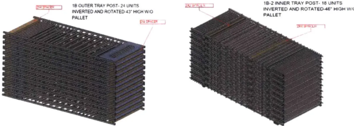
18 OUTER TRAY POST- 24 UNITS 18-2 INNER TRAY POST- 18 UNITS INVERTED AND ROTATED-43 HIGH W/O INVERTED AND ROTATED-468 HIGH W/O
PALLETPALLET
< Figure 17: Tray Post Nested Configuration >
Figure 17 shows how the tray container shelf railed posts would be stacked in each pallet. These posts were not designed to be nested, therefore they are simply stacked upon each other with spacers placed on each other to protect individual parts.
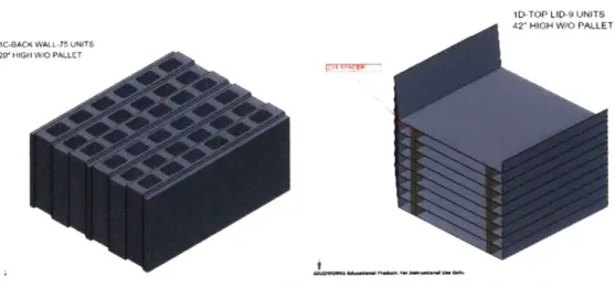
ID-TOP LID-9 UNITS 42' HIGH W/O PALLET IC-BACK WALL-75 UNITS
2(r HIGH MIG PALLET
<Figure 18: Corrugated Wall and Top Lid Nested Configuration >
Figure 18 shows the nested configuration of the corrugated walls and top lids. The corrugated walls are thick and rigid enough to be stacked without any additional packaging material. However, although the top lids are also nestable because of draft angles, they are not thick enough to support the weight of other stacked lids without bending out of shape. Therefore, some spacers are placed to distribute the weight on the top lid.
STACKMf.75 H4154 W0 PASiL FT IE-2- 23 UNITS CHW PA
TA2 HIGH WOO GA WI FATLF
< Figure 19: Tray Stacking Configuration >
Figure 19 shows how individual trays would be stacked. These trays are not designed to be nested, as any draft angle would cause loss in storage volume. Therefore they are simply stacked vertically.
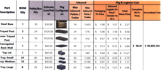
The base would be stacked in a "flower", where each base is stacked on top of each other at an angle so that the legs do not interfere with each other. This would save packing space without sacrificing the original design, but since it is stacked in a circular form, it loses some space utilization on the corners. Table 5 shows the estimated packaging and logistic
costs for each part, as well as the total cost for a whole tray container shelf and the annual estimated cost. The majority of the packaging costs are on the railed posts and top lids, which require additional packaging material and has low packing efficiency. The total cost for shipping a single tray container style shelf is $98.81.
Inbound P
It..& Letia con
Estimate Phg Max max f
DePt aon Qty Qty Cost/PaU Conftwiead 'nbound Wbound Paetaghv Pub* ft ow Mt a
SIM at an Paeits / PWft / P. P d m. Pk"Pd O ft .ral m
...
I
Vandust. PPC%Steel Be 1 30 $30.00 54 1,620 $. 1.00 $ 127 1 2.27
Trayed Post 2 24 S120.00 24 576 S 5.00 $ 358 $ 8.58
InnrwTrayed 1 18 $120.00 24 432 S 6.67 S 4.78 $ 11.44
Post fa
Coragated ack WallI 1 75 $40.00 90 6.750 $ 0.53 $ 0.31 $ 0.84
Top Lid 1 9 $85.00 60 540 $ 9.4$ 3.82 $ 1327
Tray Snag 24 80 $40.00 90 7.200 $ 0.50 $ 029 $ 0.79
Tray Medium 10 46 $40.00 a 90 4,140 $ 0.87 $ 0.50 $ 1.37
$ 98.81 $ 98,09,265
Tray Large 28 $40.00 I0 60
[
1.680 S 143 $ 123 $ 2.661< Table 5: Packaging and Logistics Cost for Tray Container Shelf >
Stackable Tote Shelf Nested Configuration
All the foldable totes are designed to be nested. Once folded, the walls can be stacked side by side like Lego pieces, with the rails nesting into another set of walls. This saves 40mm of width of every set of walls, increasing the packing density in a shipping pallet. Figure 20 shows how the foldable totes would fold and nest.
< Figure 20: Foldable Totes in Shipping Configuration > 39
< Figure 21: Bottom Totes Stacked in Shipping Configuration >
Figure 21 shows the XS size bottom totes, which are fully injection molded instead of having modular walls due to the size constraints of the hinge connection. These XS totes also nest 40mm, the height of the rails, and keeps the totes relatively compact when shipping.
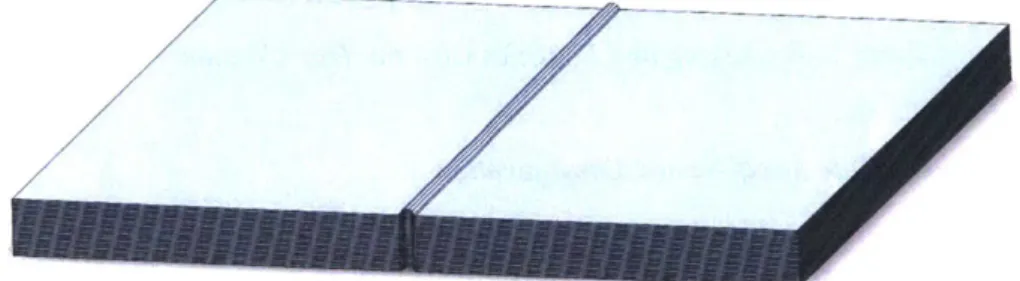
< Figure 22: Stacked Aluminum Plates >
Figure 22 shows how the aluminum plates would be stacked. These 1.5mm
aluminum sheets have a channel in the center, which is drafted 15 degrees and allows them to be nested with 3.175mm separation between plates.
The base would be stacked in the same way as the tray container style shelves, in a flowered pattern. Table 6 shows the estimated packaging and logistic costs for the stackable tote style shelf. The medium sized walls and small sized walls did not have part drawings, so
cost was estimated by extrapolating a linear relationship in size and weight. None of the parts had expensive packaging or shipping costs; all parts had high packing density and required no additional packaging material. The total packaging and shipping cost for a single stackable tote shelf was estimated $56.48, roughly half of that of tray container shelves.
-- PPeF Can PR O a
I
r*' Ut Po--+-44 -T__11
_ _ __ _ _ M Ae * x W 43 Yes 14000 so 1 490 1073 $0 11 U 3m WO 6 36 W smx4 Yes 0000 60 100 $2 1 $2 9 7 1373 W I I 110000I? 55 $4 53 r i $4060$0 S WA 6 6 4Wx4rW; 11 Yes 14000 60 3600 1027 7 102 1205NMWA U SO i s E~4 1w 713 Yes VO000 so0 100 00 S2 1091 S10
< Table 6: Packaging and Logistics Cost for Stackable Tote Shelf>
6-1c. Assembly Time & Cost
Assembly time and cost are the key aspects that were considered in both designs. Most distribution centers are very busy, and do not have skilled assembly workers. Therefore assembly was considered the most frustrating part for these shelves. Assembly time was roughly estimated by simulating by hand. In this section, the assembly cost was calculated based on estimated assembly time and an hourly wage of $40 for an assembly worker.
Tray Container ShelfAssembly
2. Rivet Top Lid to
Posts
1. Rivet Posts to Base
3. Rivet Corrugated
Wall at the back
-I
4. Insert trays accordingly
< Figure 23: Tray Container Shelf Assembly Order >
As shown in Figure 23, tray container shelves are assembled in 4 steps, after unpacking all the parts. First, the pre-assembled railed posts are inserted into the base until the bottom rail touches the base. Then the posts are riveted to the base. Second, the top lid is riveted to the posts. Thirdly, the corrugated back wall is riveted at the center of the back, with
the grooves facing inward. Lastly, all the trays are inserted into their corresponding locations. The estimated assembly time is organized in Table 7. Even with a safety factor of 1.5, the assembly time is only 12 minutes, well under the required 20 minutes per shelf. Based on this estimation, each shelf costs $8 to assemble, and about 40 shelves can be assembled per person per day.
Step Description
WkCk bm*. Paca Nid trays
Unit Thme IsI
60
uantity Total Expected Time IJ
60
1 vet ald posts to bas 30 3 90
2 %vt top td IhU "h x posh
1
_ _ 603 Mt cougaed bek wall 5 12 60
4 hno trqysonto rails accordingly 5 42 210
Total Isl X 1.5 S.F. Assembly Cost per Shelf Shelf per day [per 8 hour] per person
Number of workers needed (for 1600 shelves/day desired outpuI4
480 18 mini 720 U mini $8.oo 40 shelves 40 #0
Stackable Tote ShelfAssembly
Unpack Base Unpack walls Stack XS Totes on Base
Wrap Walls Install Screws Forklift to Stack Totes < Figure 24: Stackable Tote ShelfAssembly Order >
Similarly, stackable tote shelves have a 4-step assembly after unpacking all the parts. First, the XS size totes are fully injection molded pieces, so these are stacked on the base immediately. Next, each unpacked wall is hinged around an aluminum plate. Once wrapped around, self-tapping screws would be installed and drilled in to secure the walls to be fixed. The second and third step would be repeated for all the totes. Finally, all the completed totes are stacked according to their sizes, and piled on top of the base to complete the shelf. Figure 24 shows how the assembly process would look like.
The estimated assembly time is organized in Table 8. With a safety factor of 1.5, the total assembly time is about 17.2 minutes, roughly 50% longer than tray container style shelves but still under the required 20 minutes. Each shelf is expected to cost $11.47 to assemble, and about 28 shelves can be assembled per person per day.
Step Description
thpackbw
Unit Time (si
5
QumnUty~ Total Expected Time IS
5
2 U npedck bi1"dahmrim S 2
3 arunap d akUs idmur 24 29
4 istAutf-tappngrsaewaopandbodond 5 42 20
5 Fork it sock toles 15 5 75
Total Is) X 1.5 S.F.
Assembly Cost per Shelf
689 (115 mkis) 1034 (17.2 mins)
$1.47
Shelf per day (per 8 hour] per person 28 shelves Number of workers needed (for 1600 shelves/day desired output) 58
< Table 8: Stackable Tote Shelf Onsite Assembly Time Estimation >
#